

Whirlpool DU810SWPQ, DU810SWPT, DU810SWPU, DU811SWPQ, DU811SWPU Dimension Guide
...
Undercounter Dishwasher
PRODUCT MODEL NUMBERS OVERALL DIMENSIONS
CABINET OPENING DIMENSIONS
DU810SWP
DU811SWP
DU850SWP
Electrical: 120-volt, 60 Hz, AC-only, 15 or
20 amp, fused electrical supply. Use copper wire
only. A time-delay fuse or circuit breaker and
separate circuit is recommended.
Water: A hot water line with 20-120 psi (138862 kPa) water pressure. Water temperature must
be 120°F (49°C) at dishwasher. Use ³⁄₈" O.D. copper
tubing with compression fitting or flexible braided
fill line (1/2" minimum plastic tubing is optional but
not recommended). Use a ³⁄₈" compression x ³⁄₄"
hose fitting to connect to water inlet valve. Do not
solder within 6" (15.2 cm) from water inlet valve.
Drain: A new drain hose is supplied with
your dishwasher. If this is not long enough, use a
new drain hose with a maximum length of 12'
(3.7 m) (Part Number 3385556) that meets all
current AHAM/IAPMO test standards, is resistant to
heat and detergent, and fits the 1" (2.5 cm) drain
connector of the dishwasher.
Make sure to connect the drain hose to waste tee or
disposer inlet above drain trap in house plumbing
and 20" (50.8 cm) minimum above the floor. It is
recommended that
the drain hose either
be looped up and
securely fastened to
the underside of the
counter, or be
connected to an air
gap.
Make sure to use an
air gap if the drain hose is connected to house
plumbing lower than 20" (50.8 cm) above subfloor
or floor. Use ¹⁄₂" (1.3 cm) minimum I.D. drain line
fittings.
If required, the air gap should be installed in
accordance with the air gap installation instructions.
When you are connecting the air gap a rubber hose
(not provided) will be needed to connect to the
waste tee or disposer inlet.
Corner location: Requires a 2" (5.1 cm)
minimum clearance between the side of the
dishwasher door and wall or cabinet.
A side panel kit is available from your dealer for
installing your dishwasher at end of cabinet.
Grommet is required for electrical cable or power
supply cord hole cut in a metal cabinet.
Do not install dishwasher over carpeted floor.
Because Whirlpool Corporation policy includes a continuous commitment to improve
our products, we reserve the right to change materials and specifications without notice.
Dimensions are for planning purposes only. For complete details, see Installation
Instructions packed with product. Specifications subject to change without notice.
Ref. W10282559-D-WH
6/19/12
SIDE VIEW
REAR VIEW
Page 1 of 2
air gap
24" (61 cm)*
337⁄8"
(86 cm) min.
*to front of
door frame
203⁄4"
(52.7 cm)
24" (61 cm)**
*Measured from the lowest point on the
underside of countertop.
**Minimum, measured from narrowest point
of opening.
6"(15.2 cm)
4" (10.2 cm)
4"
(10.2 cm)
1
2
⁄
2
"
(6.4 cm)
5" (12.7 cm)
2"
(5.1 cm)
Water line entering through the
left side of opening in shaded
areas makes connection easier.
Minimum
1
⁄2" (12,7 mm) hole.
10"
(25.4 cm)
237⁄8" (60.6 cm)
24" (61 cm)
6"(15.2 cm)
4"
(10.2 cm)
1
2
⁄
2
"
(6.4 cm)
1
⁄2" (3.8 cm)
2"
(5.1 cm)
5" (12.7 cm)
Drain hose and power supply line entering through the right
side of opening in shaded areas makes connection easier.
Drain hose size: 1
Power supply line hole-direct wired:
Power supply line hole-with plug: 1
3
⁄4" (1.9 cm)
1
⁄2" (3.8 cm)
34" (86.4 cm) min.*
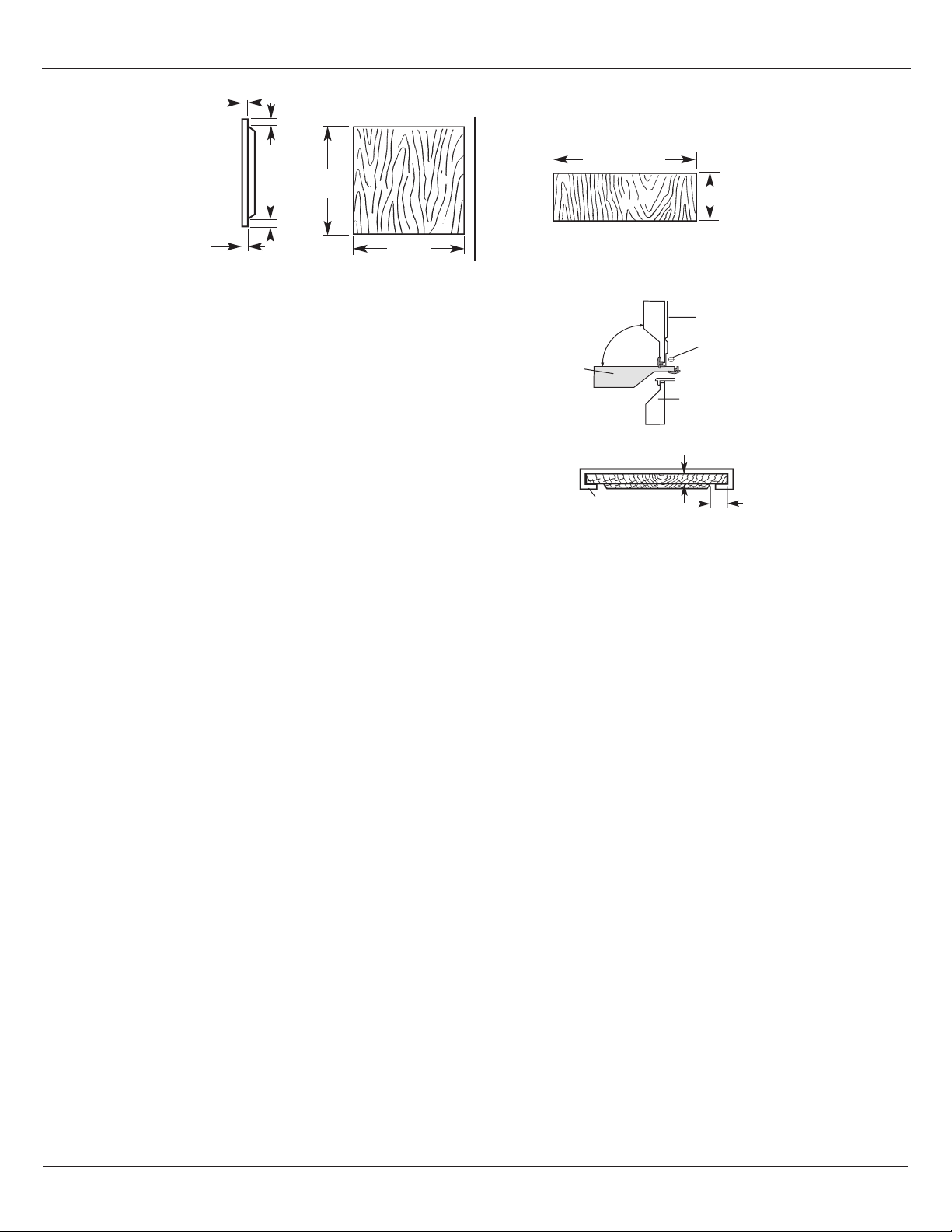
CUSTOM FRONT PANEL DIMENSIONS (Framed)
Cut door panel to clear access panel when door is in open position.
Custom door panel more than ⁷⁄₃₂" (5.6 mm) thick: Rout top and bottom to ⁷⁄₃₂"
(5.6 mm) thickness.
Custom access panel more than ⁷⁄₃₂" (5.6 mm) thick: Rout all four sides to ⁷⁄₃₂"
(5.6 mm) thickness.
Custom panels less than ⁷⁄₃₂" (5.6 mm) thick: Install spacers behind panels.
Because Whirlpool Corporation policy includes a continuous commitment to improve
our products, we reserve the right to change materials and specifications without notice.
Dimensions are for planning purposes only. For complete details, see Installation
Instructions packed with product. Specifications subject to change without notice.
Ref. W10282559-D-WH
6/19/12
Page 2 of 2
7
⁄32"
(5.6 mm)
door panel
(side view)
7
⁄32"
(5.6 mm)
These panels fit only models with frames around the door and access panels.
door panel (front view)
3
⁄8"
(9.5 mm)
1"
(25.4 mm)
1821⁄32"
(47.4 cm)
2231⁄32"
(58.3 cm)
NOTE: Access panel is wider than door panel.
235⁄16" (59.2 cm)
access panel
(front view)
All edges routed to 7⁄32" (5.6 mm) thickness.
side view
door in ope n
position
door
opened
top view
7
⁄32" (5.6 mm) thick
access panel frame
47⁄16"
(11.3 cm)
door closed
door pivot
access panel
1
⁄4"
(6.4 mm) min.
 Loading...