

Whirlpool DU1101XTPQ0, DUL240XTPQ0, DUL300XTLB3, DUL300XTLQ3, GU1100XTLB1 Service Pointer
...
REFRIGERATION PRODUCTS KITCHEN PRODUCTSLAUNDRY PRODUCTS
COMMERICAL LAUNDRY
THIS SERVICE POINTER APPLIES TO THE FOLLOWING BRANDS:
33
3
33
K8178505
March 2005
33
3
33
OEM BRANDS
WHIRLPOOL TALL TUB DISHWASHER
Models:
DU1050XTPQ0 DU1101XTPQ0 DU1145XTPQ0
DU1148XTPQ0 DUL240XTPQ0 DUL300XTLB3
DUL300XTLQ3 GU1100XTLB1 GU1100XTLQ1
GU1100XTLS1 GU1100XTLT1 GU1200XTLB3
GU1200XTLQ3 GU1200XTLS3 GU1200XTLT3
GU1500XTLB3 GU1500XTLQ3 GU1500XTLS3
GU1500XTLT3 GU2400XTPQ0 GU2500XTPQ0
GU2548XTPQ0
GU2548XTPQ0GU630XTLQ1
Serial Code date: FR22-FR24
WASH MOTOR REWORK #R14165
CONDITION:
There is a potential overheating condition in the wash pump motor. In rare instances, this condition could cause a fire.
The drain pump motor is not affected and can be reused.
RESOLUTION:
Replace the pump-motor assembly with a motor kit #8194160.
See the attached replacement procedure.
Part Kits should be ordered through Whirlpool authorized parts suppliers.
ALL SERVICE POINTERS ONLINE: http://www.servicematters.com/tech_ref/tech_ref_main.htm, SERVICE POINTERS
COMMERCIAL LAUNDRY ONLY: www.whirlpoolcorp.com/cltpsc, TECHNICAL INFORMATION, SERVICE POINTERS
To receive pointers by email or FAX, or to edit or delete a current email or Fax from our distribution, see
http://www.whirlpoolcorp.com/cltpsc/feedback/feedbacksubscribe_all.html, or FAX changes to 269-923-5342.
WASH MOTOR REPLACEMENT PROCEDURE PROJECT# R14165
UNITS INVOLVED:
Specified Whirlpool brand PLASTIC “TALL TUB” models built with-in serial range specified below:
WHIRLPOOL
FR 22 TO FR 24
CORRECTIVE ACTION:
Open the door and confirm that the dishwasher is a PLASTIC TALL TUB model and falls with-in the specified serial range
above. If the dishwasher meets this criteria, replace the wash motor assembly with part number #8194160.
NOTE: IF the dishwasher was manufactured with a stainless steel tub, is not a plastic tall tub model, or falls outside the
specified serial range above, no further action is necessary.
READ THE BELOW INSTRUCTIONS IN THEIR ENTIRETY BEFORE PROCEEDING.
WARNING
Electrical Shock Hazard
Disconnect power before servicing.
Replace all parts and panels before
operating.
Failure to do so can result in death
or electrical shock.
1. Unplug the dishwasher or disconnect power.
2. Open the dishwasher door and remove the lower dish
rack.
3. Remove the upper dish rack.
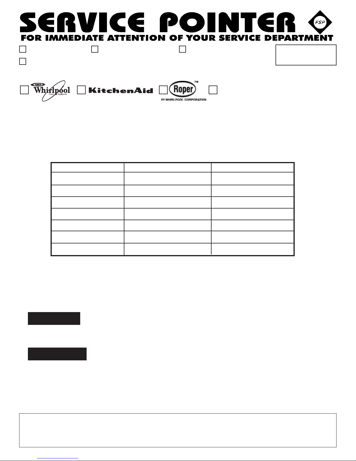
4. Remove the lower spray arm by holding the spray arm
stationary turning the center stud clockwise.
CENTER STUD
5. Remove the upper spray arm water feed tube by first
removing the two screws securing the tube to the
dishwasher tub.
6. Turn the feed tube clockwise to disengage it from the
pump and remove it from the dishwasher.
NOTE: If the dishwasher is not installed under a counter
top in a recessed area and the utilities are disconnected,
lay the dishwasher on it’s back and skip STEP 7.
7. For better access, remove outer door panel by
removing the eight T-15 Torx screws securing the panel
to the inner door.
8. Remove the lower access panel and toe panels.
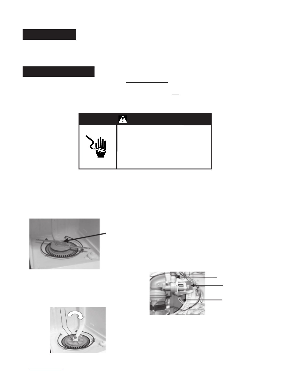
9. Remove the wiring connectors from the soil sensor
and drain pump.
NOTE: When removing terminals, grasp the terminal
behind the spade connector with a pair of locking pliers so
as not to damage it. The connector can loosen if it is
removed by rocking it. Always pull the connector straight
off.
SOIL SENSOR
DRAIN PUMP
THERMISTOR
10. Remove the thermistor by turning the thermistor one
quarter turn counterclockwise and pulling it out of the
sump.
11. Place a shallow pan or a towel under the soil sensor
to catch any water that may be present in the drain
hose.
 Loading...