

Page 1
INSTALLATION INSTRUCTIONS
FOR PREFINISHED & INTEGRATED (SINGLE & DOUBLE) MODELS
(NOTE: FOR INTEGRA TED PANEL PREPARATION INSTRUCTIONS REFER T O SUPPLIED SHEET P/N 526610)
P/N 526609C (page 1 of 8)
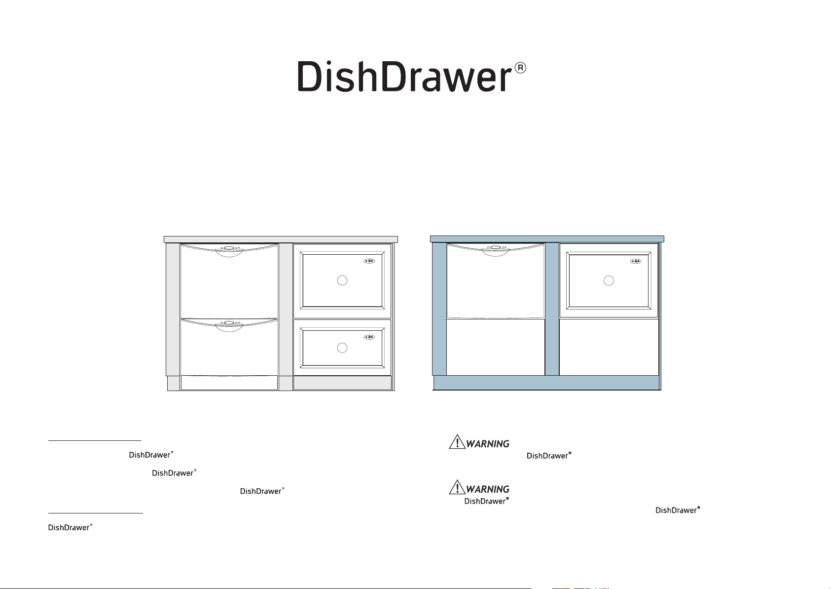
DA
DOUBLE MODELS
MODELS DD603 Pref nished DD603I Integrated
NOTE TO THE INSTALLERO
1. Read these Instructions completely and carefully.
2. Installation of this requires basic mechanical and electrical skills.
3. Be sure to leave these Instructions with the Customer.
4. At the completion of the installation, the Installer must perform Final Check List
as per Section 11 of these Installation Instructions.
5. Remove all packaging materials supplied with the .
NOTE TO THE CONSUMER
Keep these Installation Instructions with your User Guide for future reference.
must be securely anchored before it is operated.
SINGLE MODELS
MODELS DS603 Pref nished DS603I Integrated
Before installing the , remove the house fuse or open the circuit breaker. Ensure
all water connections are turned OFF. It is the responsibility of the plumber and electrician
to ensure that each installation complies with all Codes and Regulations.
The MUST be installed to allow for future removal from the enclosure if
service is required. The installer is responsible for the installation. Improper
installation is not covered under the Warranty.
Page 2
BEFORE YOU START - DOUBLE &YOU START
SINGLE MODELS
P/N 526609C (page 2 of 8)
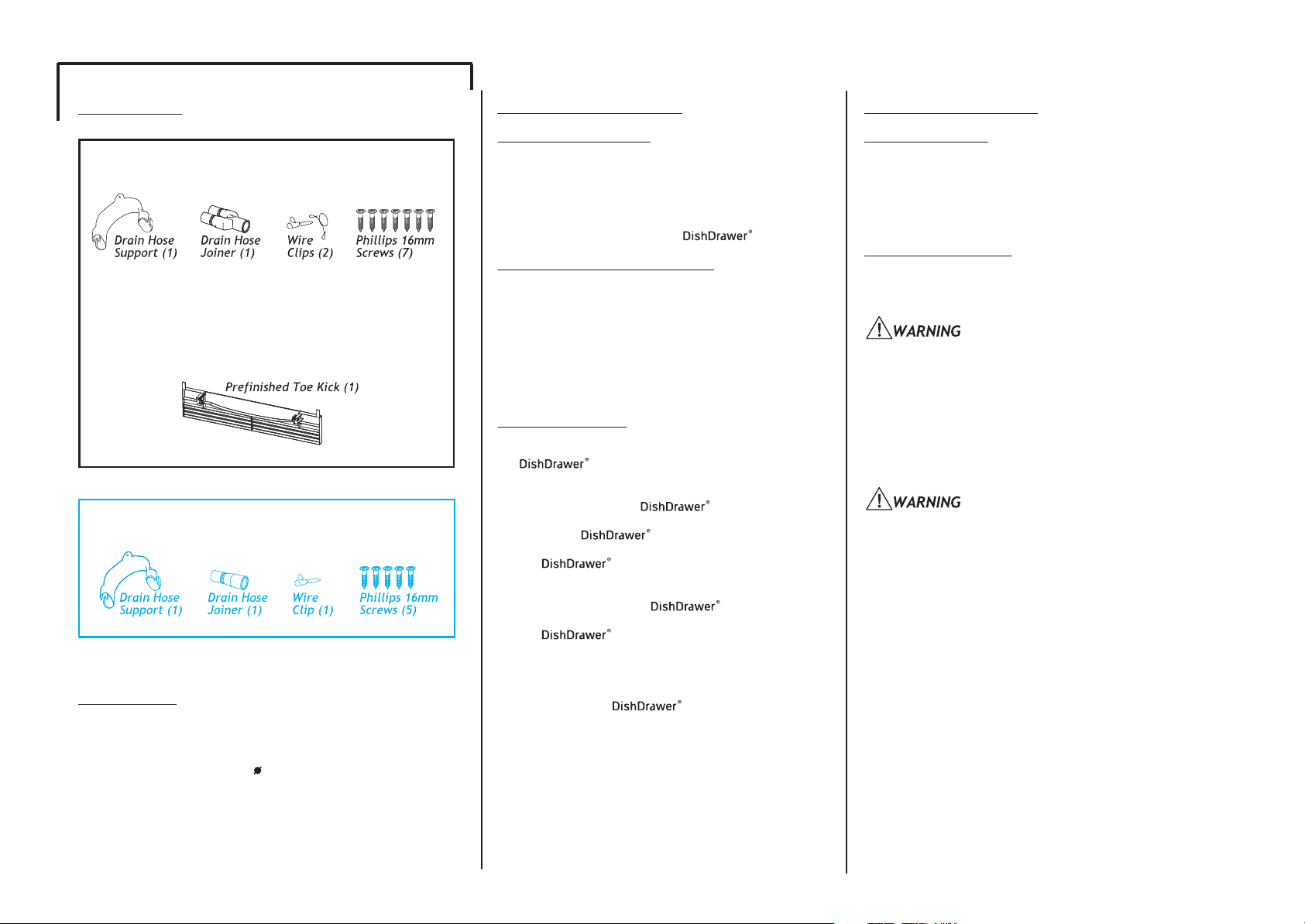
PARTS SUPPLIED
DOUBLE MODELS (INTEGRATED & PREFINISHED)
INSTALLATION KIT P/N 526677
ADDITIONAL TOE KICK KIT SUPPLIED WITH
PREFINISHED MODELS
White Pref nished Toe Kick Kit P/N 526680
or Black Pref nished Toe Kick Kit P/N 526681
SINGLE MODELS (INTEGRATED & PREFINISHED)
INSTALLATION KIT P/N 526677
TOOLS NEEDED
Wooden Chopping Board Drill & No.2 P
Tape Measure No.2 Phillips Screwdriver
Spirit Level Flat Screwdriver
Safety Glasses Adjustable Wrench or M5 Socket
Utility Knife 50mm Hole Saw
Pencil Side Cutting Pliers
Sandpaper
hillips Bit
INSTALLATION PREPARATION
ELECTRICAL PREPARATION
A) The switched power outlet for the appliance should
be installed in a cabinet or on a wall adjacent to
the under bench space in which the appliance is to be
installed. Note: The power outlet must be accessible
after installation.
B) The power outlet should be positioned between
150mm and 450mm from the cavity.
PLUMBING & DRAINAGE PREPARATION
A) A readily accessible valve must be installed in the water
supply pipe.
B) If the supply pressure exceeds 960kPa, then a
pressure limiting valve must be used.
C) Review Plumbing Options on pages 3-4. Choose a
method that best suits your needs.
D) A Drain Hose extension Kit P/N 525798 will extend the
drain hose(s) by 3.6m. The kit is available from the
nearest Fisher & Paykel Authorized Service Agent.
CAVITY PREPARATION
A) If installing mutiple products side by side a minimum
2.5mm clearance must be maintained around the
's.
B) On corner installations, ensure that there is a gap
between the adjacent cabinetry (e.g.door knobs) and
the sides of the open . A 12.7mm minimum
gap is recommended.
C) Where the is installed under a bench
top, it is recommended that bare wood surrounding
the is sealed with an oil based paint or
polyurethane to prevent possible steam damage.
D) Ensure the cavity sides are plumb (vertical) as this will
assist with leveling the
E) Ensure the cavity provides suff cient material to secure
the using the mounting tabs (refer to step
1, page 5). If there is nothing to screw to, add
something. See page 3 or 4 for screw locations.
F) The services hole MUST be immediately adjacent to the
rear lower corner of the cabinetry. If not, the hoses
will prevent the being pushed back into
the cavity all the way. The hole can be located on
either side depending on the location of the services.
.
ELECTRICAL INFORMATION
POWER SUPPLY CORD
A) Care should be taken when the appliance is installed
or removed, to reduce the likelihood of damage to the power
supply cord.
B) If the power supply cord is damaged, it must be replaced
by the Manufacturer, Service Agent or a similarly qualif ed
person, in order to avoid a hazard.
EARTHING INSTRUCTIONS
A) This appliance must be earthed. In the event of
malfunction or breakdown, earthing will reduce the risk
of electric shock by providing a path of least resistance for
electric current.
Improper connection of the equipment-earthing conductor can
result in a risk of electric shock. Check with a qualif ed
electrician or service representative if you are in doubt as to
whether the appliance is properly earthed.
B) This appliance is equipped with a power supply cord
having an equipment-earthing conductor and a earthing
plug. The power supply plug must be plugged into an
appropriate outlet that is installed and earthed in
accordance with all local Codes and Regulations.
Do not modify the power supply plug provided with the
appliance - if it will not f t the outlet, have a proper outlet
installed by a qualif ed electrician. Do not use an extension
Page 3
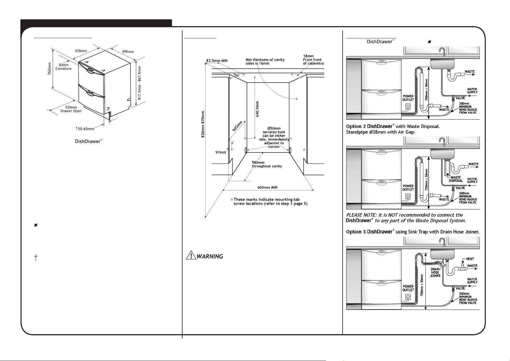
DOUBLE MODEL
SERVICE'S SPECIFICATION
P/N 526609C (page 3 of 8)
THE CAVITY
PLUMBING OPTIONS
Option 1 and Standpipe 38mm with Air Gap.
*
*,"#*,"#
--
*For an Integrated the product depth is specif ed
with an 18mm Integrated Door Panel thickness.
Water Connection
Recommended COLD
(Maximum 60°C)
3/4 " BSP (GB20)
to suit f at washer.
Water Pressure
Maximum 960kPa (139 p.s.i.)
Minimum Dynamic 30kPa (4.3 p.s.i.)
Drain Connection
Drain Hose Joiner to suit
19mm +_ 2mm waste tee.
Electrical Connection
230-240 VAC power outlet
9Amps Minimum.
++
!,!,
*+$*+$
$$
++
++
% %
&'(( )&'(( )
++
"#"#
++
++
++
NOTE: All depth measurements are taken from the front face of
the adjacent cabinetry.
Option 2 with Waste Disposal.
Standpipe 38mm with Air Gap.
PLEASE NOTE: It is NOT recommended to connect the
to any part of the Waste Disposal System.
Option 3 using Sink Trap with Drain Hose Joiner.
Toe Kick Depth
Prefinishedf
50-65mm.
Integrated
67mm less the Toe Kick Panel thickness (Minimum Panel thickness
using the supplied screws is 9mm).
Length of Services
Drain hose - 2250mm
Inlet hose - 1750mm
Power supply cord - 1965mm
NOTE: Services approximately exit product
189mm from left; 550mm from front;
793mm from top.
Ensure the edges of the services hole are smooth or covered.
NOTE: Pref nished Model is shown. There is no variation
in plumbing between Pref nished products and Integrated
products. Option 1 and 2 are the preferred options.
Page 4
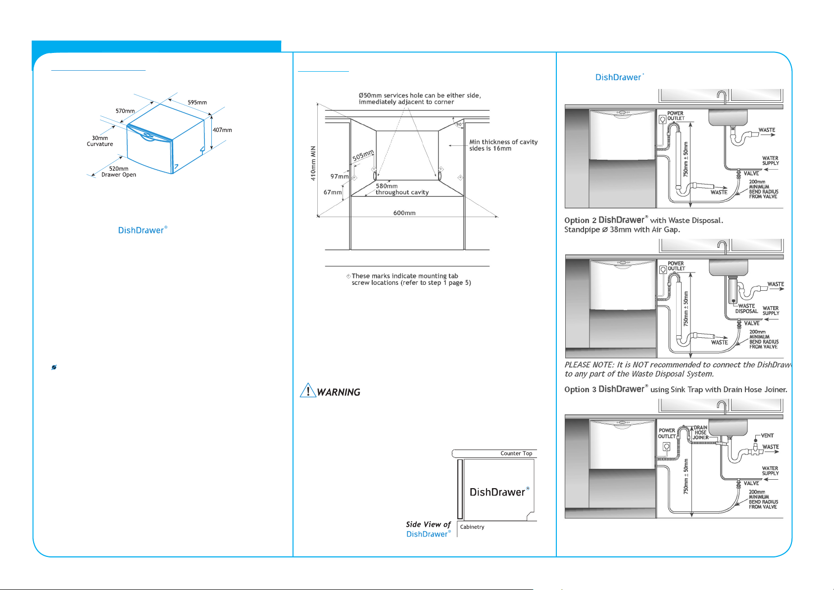
SINGLE MODEL
P/N 526609C (page 4 of 8)
SERVICE'S SPECIFICATION
*
*For an Integrated
with an 18mm Integrated Door Panel thickness.
Water Connection
Recommended COLD
(Maximum 60°C)
3/4 " BSP (GB20)
to suit f at washer.
Water Pressure
Maximum 960kPa (139 p.s.i.)
Minimum Dynamic 30kPa (4.3 p.s.i.)
Drain Connection
Drain Hose Joiner to suit
19mm +_ 2mm waste tee.
Electrical Connection
230-240 VAC power outlet
4.5Amps Minimum.
the product depth is specif ed
THE CAVITY
+
+
+
+
%
&'(( )
+
$
!"#
$
NOTE: All depth measurements are taken from the front
face of the adjacent cabinetry.
NOTE: To align drawer front to adjacent cabinetry, the
product to counter top clearance can be increased
from 3mm.
Ensure the edges of the services hole are smooth or covered.
PLUMBING OPTIONS
Option 1 and Standpipe 38mm with Air Gap.
Option 2
Standpipe 38mm with Air Gap.
PLEASE NOTE: It is NOT recommended to connect the DishDrawer
to any part of the Waste Disposal System.
Option 3 using Sink Trap with Drain Hose Joiner.
with Waste Disposal.
Weight
Full 42kg Pref nished
Empty 28kg Pref nished
Length of Services
Drain hose - 2250mm
Inlet hose - 1750mm
Power supply cord - 1965mm
NOTE: Services approximately exit product
189mm from left; 550mm from front;
793mm from top.
Cabinetry must
not extend beyond
cavity base
NOTE: Pref nished Model is shown. There is no variation
in plumbing between Pref nished products and Integrated
products. Option 1 and 2 are the preferred options.
Page 5
INSTALLATION INSTRUCTIONS
PLEASE NOTE: Your model of may differ from the model shown in the installation diagrams. Installation is similar for Integrated & Pref nished products for either Single or Double models.
Information referring to Single models only is highlighted in blue. Installation diagrams have been simplif ed to enable clearer instruction. FOR INTEGRATED PRODUCTS FOLLOW THE INTEGRATED PANEL PREPARATION
INSTRUCTIONS P/N 526610, BEFORE MOVING THE PRODUCT INTO THE CAVITY.
READ THESE INSTRUCTIONS
COMPLETELY AND CAREFULLY.
P/N 526609C (page 5 of 8)
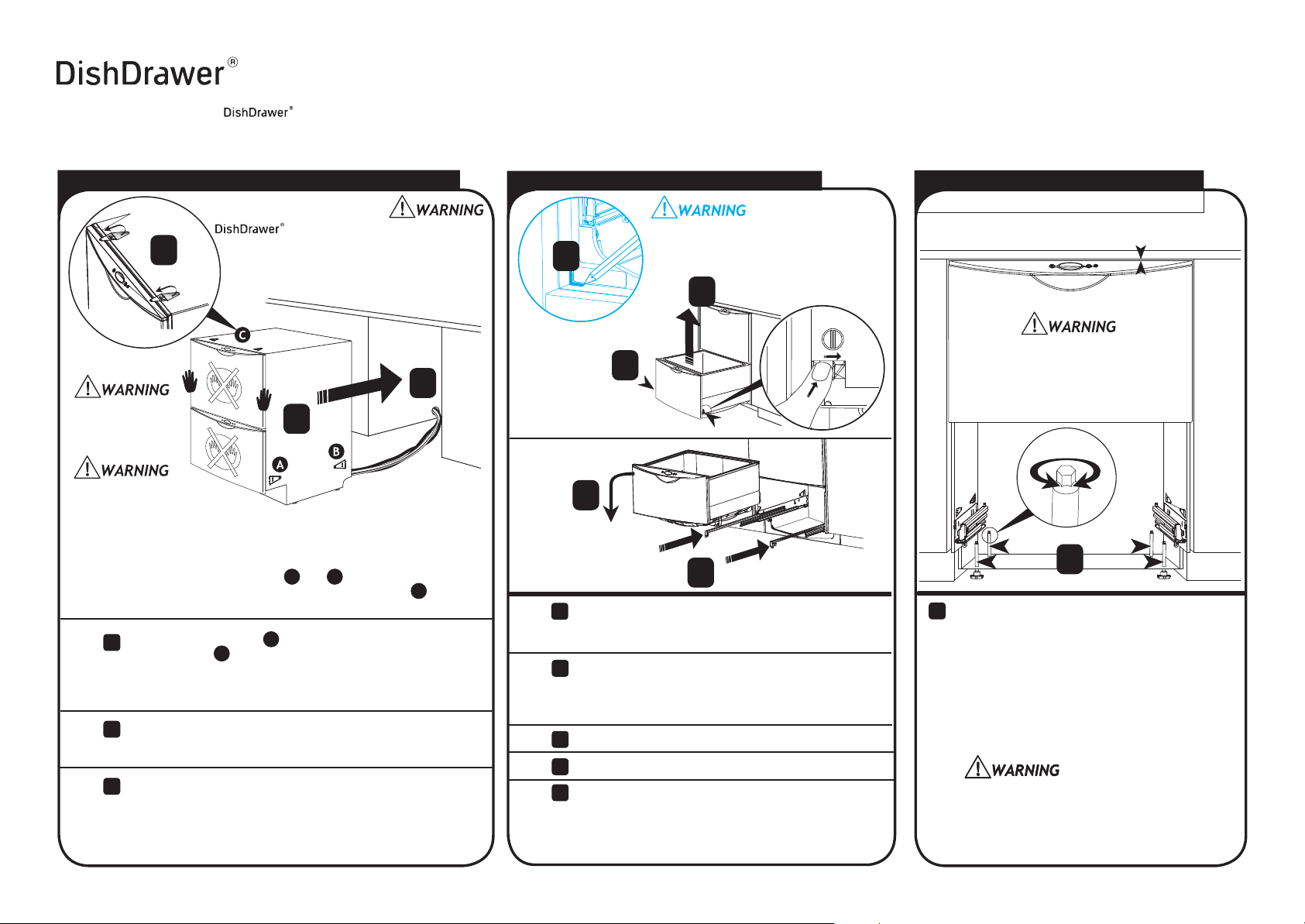
1 MOVING THE PRODUCT INTO THE CAVITY
must be free to close completely.
1
With overlapping integrated draw fronts a
(2.5mm) clearance must be maintained
between draw front and cabinetry.
2
DO NOT push
middle of
drawers.
Be careful of
sharp edges.
MOUNTING TAB OPTIONS
The mounting tabs are in pairs, one on each side of the product. They are
used to secure the product to the cavity sides. Installation requires two
sets of tab pairs be used, for example and tab pairs. All tabs
would be optimum. A minimum installation requires that the mounting
tabs be used.
DOUBLE MODELS ONLY Mounting Tab Option
1
If the top tabs are to be used, bend both tabs forward
before pushing the product into the cavity. Partially lift top
mounting tabs by inserting a f at screwdriver into the vee
shaped slot.
Check cavity for any obstructions that may interfere with
2
sliding the product back. Loosen the feet DOUBLE MODELS
ONLY
Push product into cavity to suit adjacent cabinetry. Do not
3
push middle of drawer(s). Ensure inlet, drain hose(s) and
power supply cord are not restricted or damaged by carefully
pulling them through the services hole, while the product is
being pushed back into the cavity.
C
3
A B
B
C
2 REMOVING
4
8
SINGLE MODELS ONLY. Gently open the drawer
4
and mark the chassis position on the cavity, before
removing the tub.
Open the drawer (Bottom drawer in DOUBLE MODELS.
5
Release the tub by depressing the right hand tub clip
and pushing it back 30mm. Repeat on the left hand
side.
Lift the tub up off the drawer runners.
6
Slide both runners back into the product.
7
Place the tub onto the f oor.
8
For SINGLE MODELS, depending on the height of the
cavity, the tub will need to be supported, eg. on a
chair.
THE
TUB
(SINGLE MODELS ONLY). The product
may move. Mark chassis position on
cavity.
6
5
7
3 ADJUSTING THE FEET
DOUBLE MODELS ONLY
MINIMUM CLEARANCE TO
UNDERSIDE OF COUNTER 2.5mm
The product should NOT support
any part of the kitchen cabinetry.
9
DOUBLE MODELS ONLY
9
Adjust the height of the product to suit the
cabinetry, by turning the feet from inside the
product using a wrench or M5 socket. TIP - gently
take the load off each foot using the slide and
then turn by hand.
NOTE: For integrated products, align the top
of the upper panel with the top of the
adjacent cabinetry.
The product must be levelled to within
2.5mm from front to back, and side to
side. TIP - Place a spirit level on the
drawer runners to level the product.
Page 6
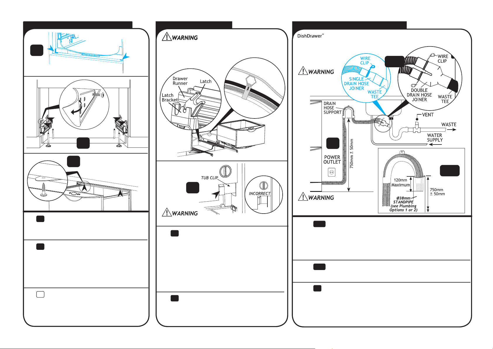
4 SECURING THE PRODUCT
10
5 REFITTING THE TUB
Before ref tting the tub, ensure the hoses are not
twisted and the latches at the rear of each drawer
runner are facing
forward.
13
6 CONNECTING THE DRAIN HOSE(S)
with Hose Joiner (see Plumbing Options).
Remember to slip the
wire clip(s)
on the drain hose(s)
first
The Drain Hose
Support must be
used.
15a
P/N 526609C (page 6 of 8)
11
12
SINGLE MODELS ONLY
10
Check the position of the chassis is still
where marked on the cavity, before securing
the product.
Fold out the sound insulation to reveal
11
each of the side tabs. Screw the side tabs
to the cavity cabinetry. Use the supplied
Phillips 16mm screws. Tabs can accomodate
a maximum of 19mm horizontal gap.
Make sure the insulation is folded back in
place to ensure the tub does not catch on
it.
DOUBLE MODELS ONLY
12
Screw the two top tabs to the underside
of bench. Use the supplied Phillips 16mm
screws. Tabs can accomodate a maximum of
19mm vertical gap.
NOTE - SINGLE MODELS do
not have top tabs.
14
Ensure the tub clips on both sides are reset.
While the tub is removed, it can be
13
rotated or turned upside down. This will
cause the hoses to become twisted. Reverse
the direction to unwind the hoses before
ref tting the tub.
To ref t the tub, make sure both of the
latches at the rear of each drawer runner
are facing forward. Ensure hoses are
hooping upward. Place the tub on the half
open drawer runners and close the draw.
Check the tub clips have reset on both sides
14
of the tub. If not, pull the tub clips forward
until the tub clip button is reset.
16
Ensure the Drain Hose(s) are fully
extended.
15a
15b
16
Slip a wire clip over each drain hose, then push the hoses into
the Drain Hose Joiner f rmly, 5 clicks. Position the wire clip(s)
between the two positioning ribs on the Drain Hose Joiner.
Attach the Drain Hose Joiner to the waste tee (see Plumbing
Options). Ensure a snug f t. If required a hose clamp may be
used.
When using the standpipe option (see Plumbing Options),
hose(s) should not extend further than 120mm down the
standpipe, in order to prevent siphoning.
Attach the Drain Hose Support to the cabinetry (with the screw
supplied) to prevent siphoning and to keep the drain hose(s)
from kinking. If required, the Drain Hose(s) may be trimmed
to a suitable length.
15a
Page 7
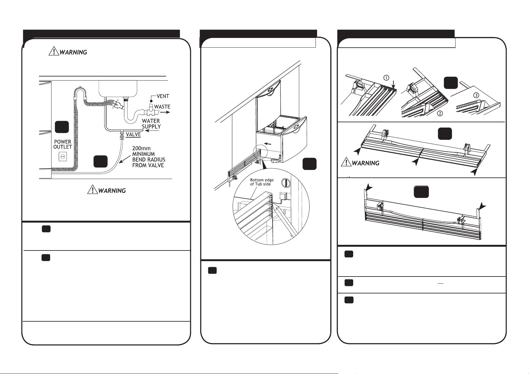
7 CONNECTING THE INLET HOSE & POWER SUPPLY 9 TRIMMING THE TOE KICK
DO NOT plug the Product in at
this stage.
8 MEASURING THE TOE KICK
DOUBLE MODELS ONLY
DOUBLE MODELS ONLY
IMPORTANT - Before cutting ensure the Toe Kick is positioned on
a wooden chopping board to avoid damage to surrounding area.
18
P/N 526609C (page 7 of 8)
20
21
17
DO NOT adjust the length of
the Inlet Hose.
Connect the Inlet Hose to the water supply. Ensure the
17
sealing washer is in place. The hose coupling must be
tightened a further half turn after seal contact. TIP -
Turn the water valve ON to check for any leaks.
Ensure there is a power outlet in reach of the power
18
supply cord. If there is not a suitable outlet available
then have one installed by a qualif ed electrician.
NOTE: SINGLE MODELS DO NOT HAVE A TOE KICK TO INSTALL.
PROCEED TO STEP 11 FINAL CHECK LIST.
Partially open the bottom drawer. Turn
19
Pref nished Toe Kick upside down and hold
vertically against the bottom edge of the
Tub side (not the drawer front)
Mark the position of the bottom edge of the
Tub side on the Toe Kick.
Choose the nearest groove to the pencil
mark which will result in the shortest Toe
Kick.
19
Remove all sharp edges
On the choosen groove cut down the vertical ribs at the
18
centre and the ends using a knife. Cut along full length
with a knife. Turn Toe Kick over, bend and then cut from
front. Sand or scrap bottom edge to remove rough patches.
To avoid a cutting hazard remove all sharp edges after
19
trimmong
Remove Toe Kick tabs by snapping them off.
20
22
Page 8
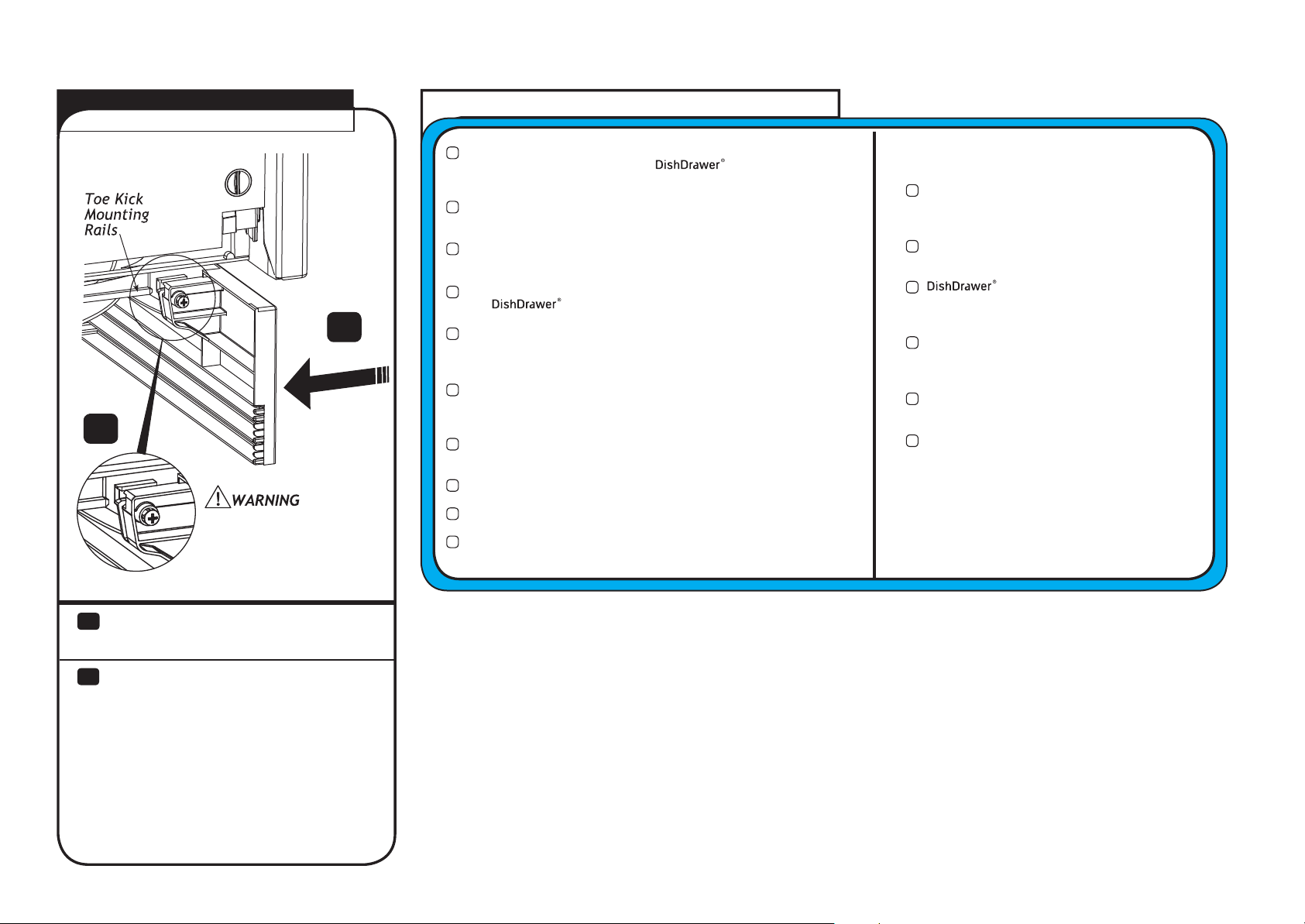
10 FITTING TOE KICK TO PRODUCT
(DOUBLE MODELS ONLY)
11 FINAL CHECK LIST - DOUBLE &
P/N 526609C (page 8 of 8)
SINGLE MODELS
24
23
DO NOT over tighten screws.
Overtightening will damage
the plastic mounting detail.
Ensure product is level, securely fastened to the cabinetry
and opens and closes freely. The must be free
to close with no resistance from the cabinetry.
Ensure inlet hose to valve connection is tightened a
further half turn after seal contact.
Ensure any knockouts or plugs in drain connection have
been drilled out and drain connection has been made.
Turn ON the power and water supply.
The should beep and light up.
Open the drawer(s) and check operation of Wash
Programme Control Panel and check the sprayarm(s) are
in place and free to rotate.
On the Wash Programme Control Panel select Rinse and
close the drawer(s). Start the programme by pressing the
Start/Pause button.
After the Rinse programme has f nished, ensure machine
has run and drained correctly.
Check water supply and drainage connection for leakage.
Repeat for each Drawer.
LEAVE ALL LITERATURE WITH CUSTOMER.
TROUBLE SHOOTING
Excessive water remaining above the f lter
plate, after the rinse cycle; check for kinked
drain hoses or blocked waste connection.
No water supply; check water is connected,
ON and there is water pressure.
does not light up when the tub is
opened; ensure power is connected and is
switched ON.
Water around water supply and drainage
connections - check connections, existing
plumbing and hoses for leaks.
If a fault occurs, consult the Fault Code
Section of the User Guide.
If unable to resolve, contact your Customer
Care Centre.
Partly open bottom drawer. Position Toe Kick
23
behind door and slide onto the mounting rails
on the underside of tub.
Close bottom drawer, check if f ush with
24
adjacent cabinetry. If required open drawer
and adjust.
When Toe Kick is in position, open bottom
drawer and gently fasten the
Toe Kick screws, on each side.
 Loading...