

N C
CONTENTSGB
FEATURES Pages 25
BEFORE USING THE COOKTOP Page 25
TIPS FOR SAFEGUARDING THE ENVIRONMENT Page 25
INSTALLATION Page 26
WARNINGS FOR THE USE OF ELECTRICAL APPLIANCES Page 28
PRECAUTIONS AND GENERAL SUGGESTIONS Page 28
GLASS CERAMIC COOKTOP Page 28
CLEANING AND MAINTENANCE Page 30
TROUBLE-SHOOTING GUIDE Page 30
AFTER-SALES SERVICE Page 30
24
M Y
24
N C
FEATURES
CKH 432 - CKH 462 - CKH 472
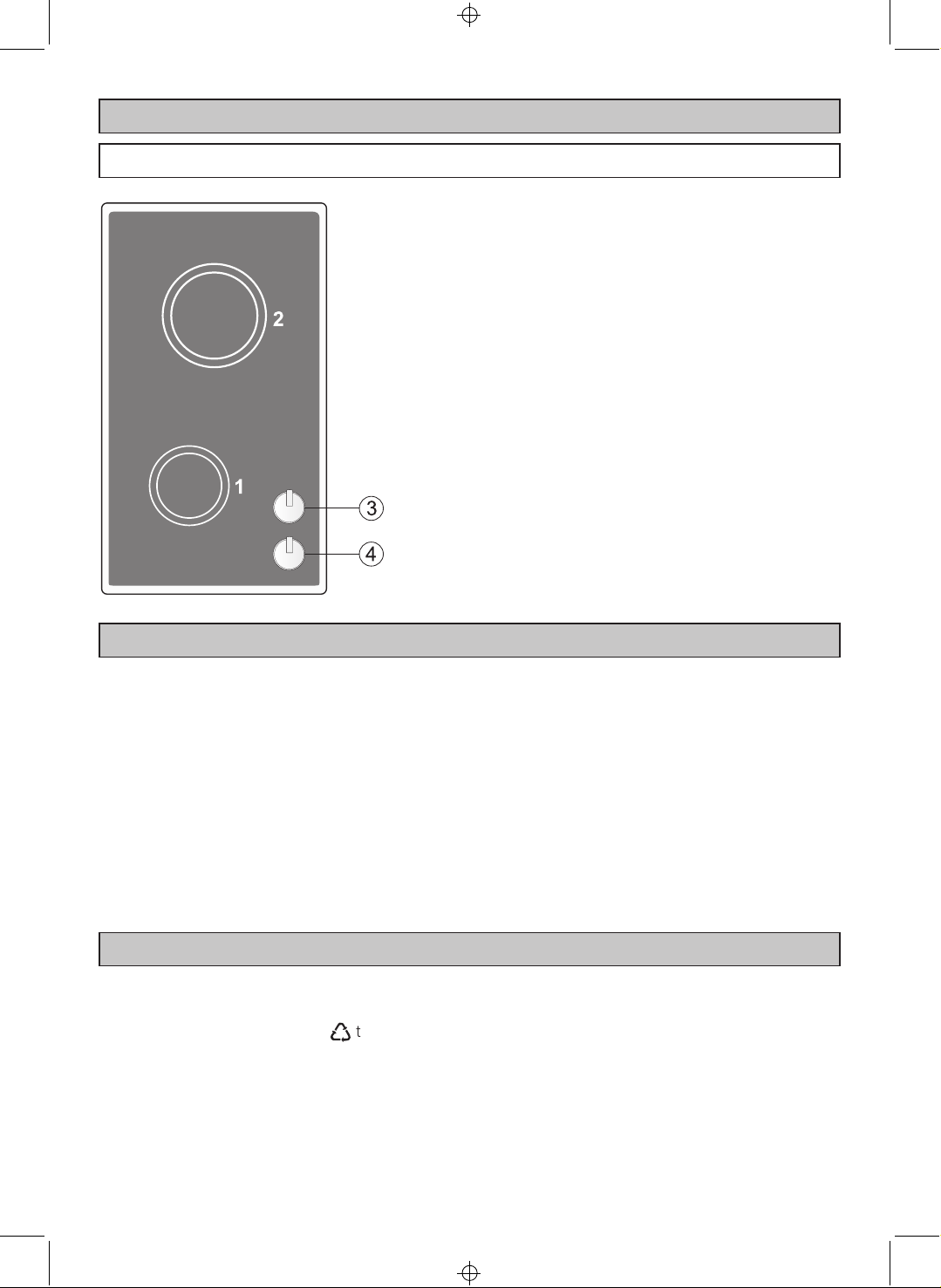
GLASS CERAMIC COOKTOP
COOKING ZONES
1. Cooking zone Ø 145
2. Cooking zone Ø 180
CONTROL PANEL
3. Rear zone contr ol knob (2)
4. Front zone control knob (1)
BEFORE USING THE COOKTOP
x
For best use of your cooktop, read the
instructions for use carefully and keep them in
asafeplace.
x
This appliance must only be used for the
purpose for which it was designed, i.e. for
cooking foods.
Any other use should be considered incorrect
and therefore dangerous.
x
The manufacturer declines all responsibility for
damage caused by unreasonable, incorrect or
rash use of the appliance.
TIPS FOR SAFEGUARDING THE ENVIRONMENT
1. Packaging
The packaging material is 100% recyclable and is
marked with the recycling symbol
type of material which must be taken to the local
collection centres.
to identify the
Ù
x
Do not try to alter the technical features of
the appliance, because this could be very
dangerous.
x
Packaging materials (plastic bags, polystyrene pieces,
etc...) must be stored out of the reach of children as
they are potentially dangerous.
x
Check that the cooktop has not been damaged
during transport. If in doubt, consult a specialised
engineer.
x
Make sure that the installation and electrical
connections are made by a qualified electrician
following the manufacturer’s instructions and
in compliance with local regulations in force.
2. Product
The cooktop has been manufactured with recyclable
material. Dispose of it following the local regulations
for the disposal of waste.
Before disposing of it make it unusable by cutt ing
off the supply cable.
25
M Y
25
N C
INSTALLATION
Technical information for installation
The installation must be performed according to the
manufacturer’s instructions and in conformity with the
local regulations in force.
When fitting the hob in the unit remember that the
coatings of the walls of the unit or devices adjacent to
the hob must be heat resistant (“Y” protection against
heating according to standards EN 60335-2 6).
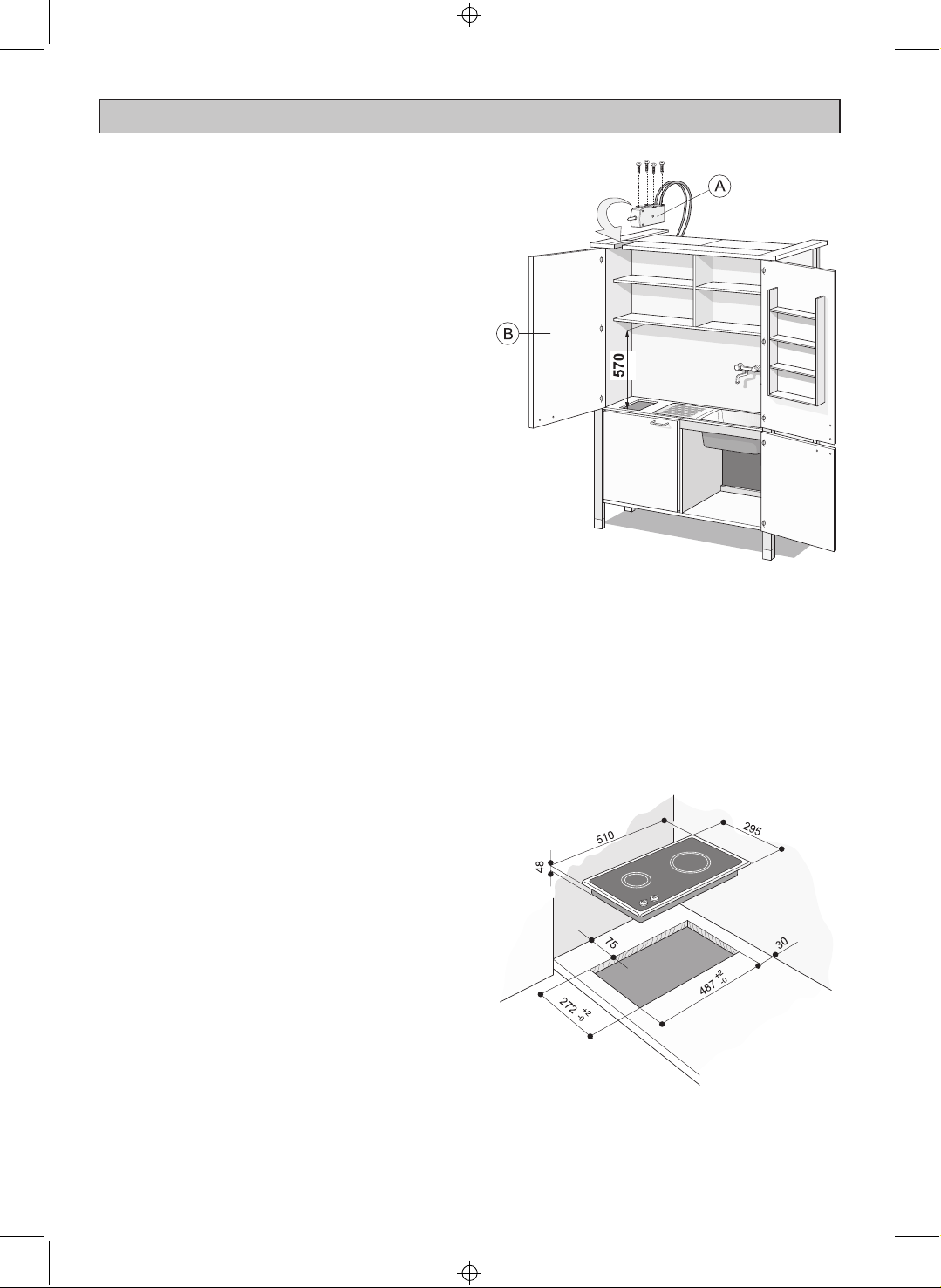
This hob can be built into a working surface 30 to 40
mm thick and 600 mm deep.
Before fitting the hob inside the unit, make sure that
the micro-switch box (A) has been fastened in place
(fig. 1) using the four screws supplied with the unit.
N.B.
– For correct installation refer to the assembly
instructions inside the unit.
– The micro-switch box (A) is a device which cuts the
power supply to the electric hotplates if the unit
door (B) is closed accidentally, thus preventing the
door being damaged by the excessive heat. It
should not be considered a hob safety device.
– The hob can only be used with the unit door (B)
completely open.
fig. 1
26
M Y
26

N C
INSTALLATION
FASTENING THE HOB TO THE UNIT
Use the brackets (C) supplied with the hob.
Position the brackets in correspondence with the holes
of the hob and fasten them to the unit with the scr ews
supplied as shown (fig. 2).
ELECTRICAL CONNECTION
IMPORTANT: The installation must be performed
according to the manufacturer’s instructions.
Incorrect installation may lead to damage to
people, animals or things for which the
manufacturer cannot be considered responsible.
– The connection to the electrical mains must be
performed by qualified engineers and according to
the regulations in force.
– The device must be connected to the electrical
mains checking first of all that the voltage
corresponds to the value indicated in the rating
plate.
– Ifthereisaplugitmustbeconnectedtoasocket
connected to the earth system in conformity with
the safety regulations.
– The connection can be made directly to the mains
putting an omnipolar switch with minimum opening
between the contacts of 3 mm between the device
and the electrical mains.
fig. 2
– The supply cable must not touch hot parts and must
be so positioned that the temperature o f 75
not exceeded at any point.
– When the device is installed, the switch or the
socket must always be accessible.
– The device must have its own power supply. Any
devicesinstalledneartoitmusthaveaseparate
power supply.
N.B.: Do not use adapters, reductions or distribution
blocks for the connection to the mains because these
could cause overheating or burns.
If the installation requires modifications of the home
electrical system or if there is incompatibility between
the socket and the device plug, professionally trained
engineers must perform the work. In particular they
must check that the section of the socket cables is
suitable for the power absorbed by the device.
The device must be connected to the earth
system.
The manufacturer declines any responsibility
for any problem caused by failure to observe
this rule.
o
Cis
27
M Y
27

N C
WARNINGS FOR THE USE OF ELECTRICAL APPLIANCES
x
When using electrical appliances some
important rules must always be followed. In
particular:
x
Never touch the appliance with wet or damp hands
or feet.
Never use the appliance with bare feet.
x
Keep children away from the hob when it is in use.
x
Before any cleaning or maintenance, switch off the
electricity to the cooktop.
PRECAUTIONS AND GENERAL SUGGESTIONS
x
Risk of fire!
Do not leave inflammable material on the cooktop.
x
Make sure that the electrical cables of other
appliances installed nearby cannot come into
contact with the cooktop.
x
Keep children away from the appliance, especially
when it is being used.
x
During and immediately after use some parts of the
cooktop reach very high temperatures.
Do not touch them.
x
Never cook the food directly on the glass ceramic
cooktop, but in special pans or containers.
EC Declaration of conformity n
x
This cooktop is intended to come into contact with
food products and conforms with European
Directive 89/109/EEC.
x
This cooktop has been designed for use only as a
cooking appliance. Any other use (e.g. heating
rooms) should be considered incorrect and therefore
dangerous.
x
This cooktop has been designed, constructed and
put on to the market in conformity with:
- Safety requirements of the “Low Voltage”
Directive 73/23/EEC and amendments;
- Protection requirements of the “EMC” Directive
89/336/EEC and amendments;
- Requirements of Directive 93/68/EEC.
- Electrical insulation Class I.
GLASS CERAMIC COOKTOP
The cooktop’s glass ceramic surface allows rapid
vertical heat transmission from the heating elements
under the cooktop to the p ans on it .
The heat does not propagate horizontally and thus the
cooktop remains “cold” just a few centimetres away
from the cooking zone.
The two cooking zones are indicated by two circles
drawn on the glass ceramic surface.
Before switching on the cooktop make sure that it is
clean.
ATTENTION
During and after use of the electric hotplates
the cooktop becomes hot.
Keep children away.
TABLE FOR USE OF THE
COOKING ZONES 1-6
For melting (butter, chocolate).
To keep food warm and to heat small
quantities of liquids.
To heat larger quantities, whip creams
and sauces.
Slow boiling, e.g.: boiled vegetables,
spaghetti, soups, continuing steam
cooking of roasts, stews.
For all types of fried foods, chops, steaks,
cooking without lid, e.g. risotto.
Browning meats, roast potatoes,
fried fish and to boil large
quantities of water.
Quick frying, steaks in steak pan, etc.
knob
1-2
2
3
3-4
4
4-5
6
28
M Y
28

N C
GLASS CERAMIC COOKTOP
TIPS FOR QUICK AND CORRECT
COOKING:
− To shorten the cooking time, when switching on the
cooktop turn the knob to maximum. After a short
time, turn the knob to the position required for
cooking.
− Use flat-bottomed cookware.
For best energy use the bottom o f the p an should
be of the same diameter as (or slightly larger than)
the cooking zone.
− As the cooking zone remains hot for some time
after the cooktop is switched off, turn the zone off
a few minutes before the end of cooking.
The residual heat will complete the cooking.
ADVICEFORSAFEUSEOFTHE
COOKTOP
− Before switching on make sure that you have the
correct knob for the hotplate chosen. It is advisable
to put the pan on the hotplate before switching on
andtotakeitawayafterswitchingoff.
Attention:
Use cookware with flat and even bottoms. Uneven
bottoms can scratch the glass ceramic surfaces. Be
careful that the bottom is clean and dry.
− Make sure that the handles of cookware do not
stick out over the edge of the cooker, to avoid them
being knocked over by accident. This also makes it
more difficult for children to reach the cooking
vessels.
− Do not lean over the cooking zones when they are
switched on.
− Do not drop heavy or sharp objects on the glass
ceramic cooktop. If the surface is broken or
damaged unplug the cooktop and cont act the aftersales service.
− Do not put aluminium foil or plastic objects on the
cooking zones when they are hot .
− Remember that the cooking zones remain hot for
some time after they are switched off (about 30
min.).
− Follow the cleaning instructions carefully.
− Do not use the glass ceramic cooktop as a
work surface.
29
M Y
29

N C
CLEANING AND MAINTENANCE
CLEANING THE GLASS CERAMIC
COOKTOP
Make sure that the cooktop is switched off before
cleaning it.
Remove any encrustation using a special scraper which
can be bought.
Remove dust with a damp cloth.
Detergents can be used, but they must not be abrasive
or corrosive.
Any remaining detergent must be completely removed
with a damp cloth.
Do not put any objects on the cooktop which can melt
with heat, such as plastic objects, aluminium foil, sugar
or sugar products.
TROUBLE-SHOOTING GUIDE
The cooking zones do not heat up.
Check whether:
x
the corresponding regulating knob has been turned
to the correct power?
x
there is a power cut?
AFTER-SALES SERVICE
If any object melts on the cooktop, remove it
immediately (while the cooktop is still hot) using a
special scraper, to prevent any irreversible damage to
the glass ceramic surface.
Do not use knives or sharp objects which could
damage the cooktop surface.
Do not use abrasive sponges or pads which could
irreversibly damage the glass ceramic surface.
Do not use steam jet cleaners because the
humidity could infiltrate into the appliance
making it dangerous.
x
Has the micro-switch box been correctly installed?
Before contacting the After-Sales Service:
1. Check whether you can deal with the problem
yourself (See “Trouble- Shooting Guide”).
2. Switch on the appliance again to check whether the
problem has been solved.
3. If it is still not working properly, call the After-Sales
Service.
IMPORTANT: The hob and microswitch box must only
be repaired by an After-Sales Service Centre authorised
by Whirlpool.
Give:
x
Thetypeoffault
x
The model
x
The Service number (the number afte r the word
SERVICE on the rating plate underneath the cooktop,
on the guarantee and on this instruction manual).
x
Your full address and post code
x
Your telephone number
x
When you can be contacted.
30
l
M Y
30
 Loading...