

Whirlpool CHW9900VQ1, CHW9900VQ0 Installation Guide
WASHERINSTALLATIONINSTRUCTIONS
Commercial Automatic Washer
Laveuse Automatique
Table of Contents
WASHER SAFETY .............................................................. 1
INSTALLATION REOUIREMENTS ..................................... 2
Tools and Parts ................................................................ 2
Options ............................................................................ 3
Location Requirements ................................................... 3
Drain System ................................................................... 4
Electrical Requirements ................................................... 4
INSTALLATION INSTRUCTIONS ....................................... 5
Remove Transport System .............................................. 5
Connect the Inlet Hoses .................................................. 5
Route the Drain Hose ...................................................... 6
Secure the Drain Hose .................................................... 7
Level the Washer ............................................................. 7
Complete Installation ....................................................... 7
SETUP INSTRUCTIONS .................................................... 8
General User Information ................................................ 8
Control Setup Procedures ............................................... 8
Start Operating Setup ..................................................... 9
Washer Diagnostic Mode .............................................. 12
CLEANING YOUR WASHER ............................................ 13
Water Inlet Hoses .......................................................... 13
ASSISTANCE OR SERVICE ............................................. 14
Accessories ................................................................... 14
WARRANTY ...................................................................... 15
Table des Mati@es
SECURITE DE LA LAVEUSE ........................................... 16
EXIGENCES D'INSTALLATION ....................................... 17
Outillage et pi_ces ......................................................... 17
Options .......................................................................... 17
Exigences d' emplacement ............................................ 17
Syst_me de vidange ...................................................... 18
Sp6cifications 61ectriques ............................................. 19
INSTRUCTIONS D'INSTALLATION ................................. 19
D6pose du syst_me de transport .................................. 19
Raccordement des tuyaux d'alimentation ..................... 20
Acheminement du tuyau de vidange ............................. 21
Immobilisation du tuyau de vidange ............................. 21
R6glage de I'aplomb de la laveuse ............................... 21
Achever I'installation ..................................................... 22
INSTRUCTIONS DE CONFIGURATION .......................... 22
Information g6n6rale pour I'utilisateur ........................... 22
Proc6dures de r6glage des syst_mes de commande...23
Param6trage pour mise en marche ............................... 24
Mode de diagnostic de la laveuse ................................. 26
NETTOYAGE DE LA LAVEUSE ........................................ 27
Tuyaux d'arriv6e d'eau .................................................. 28
ASSISTANCE OU SERVICE ............................................. 29
Accessoires ................................................................... 29
GARANTIE ........................................................................ 30
WASHERSAFETY
Your safety and the safety of others are very important.
We have provided many important safety messages in this manual and on your appliance. Always read and obey all safety
messages.
This is the safety alert symbol.
This symbol alerts you to potential hazards that can kill or hurt you and others.
All safety messages will follow the safety alert symbol and either the word "DANGER" or "WARNING."
These words mean:
You can be killed or seriously injured if you don't immediately
follow instructions.
You can be killed or seriously injured if you don't follow
instructions.
All safety messages will tell you what the potential hazard is, tell you how to reduce the chance of injury, and tell you what can
happen if the instructions are not followed.
W10179179A

IMPORTANT SAFETY INSTRUCTIONS
WARNING: To reduce the risk of fire, electric shock, or injury to persons when using the washer, follow basic
precautions, including the following:
[] Read all instructions before using the washer.
[] Do not wash articles that have been previously
cleaned in, washed in, soaked in, or spotted with
gasoline, dry-cleaning solvents, other flammable,
or explosive substances as they give off vapors
that could ignite or explode.
[] Do not add gasoline, dry-cleaning solvents, or
other flammable, or explosive substances to the
wash water. These substances give off vapors
that could ignite or explode.
[] Under certain conditions, hydrogen gas may be
produced in a hot water system that has not been
used for 2 weeks or more. HYDROGEN GAS IS
EXPLOSIVE. If the hot water system has not
been used for such a period, before using the
washing machine, turn on all hot water faucets
and let the water flow from each for several
minutes. This will release any accumulated
hydrogen gas. As the gas is flammable, do not
smoke or use an open flame during this time.
SAVE THESE INSTRUCTIONS
Do not allow children to play on or in the washer. Close
supervision of children is necessary when the washer is
used near children.
Before the washer is removed from service or discarded,
remove the door or lid.
[] Do not reach into the washer if the drum, tub or agitator
is moving.
[] Do not install or store the washer where it will be
exposed to the weather.
[] Do not tamper with controls.
[] Do not repair or replace any part of the washer or
attempt any servicing unless specifically recommended
in this manual or in published user-repair instructions
that you understand and have the skills to carry out.
[] See "Electrical Requirements" for grounding instructions.
INSTALLATIONREQUIREMENTS
Parts supplied for PD Models:
[] Service door lock cam
Gather the required tools and parts before starting installation.
The parts supplied are in the washer drum.
Tools needed for connecting the water inlet hoses
[] Pliers (that open to [] Flashlight (optional) [] Screws (2)
19A6"[39.5 mm]) Alternate Parts
Tools needed for installation
[] Open end wrenches
14 mm and 13 mm
[] Level
Parts supplied
A B
E
[] Wood block
[] Ruler or measuring tape
c D
A. U-shaped hose form
B. Water inlet hoses (2)
C. Inlet hose washers (4)
D. Transit bolt hole plug (4)
E. Beaded tie strap
Parts supplied for PR Models:
[] Card reader bezel
[] Card reader wire harness
Your installation may require additional parts. If you are
interested in purchasing one of the items listed here, call the toll-
free number in the "Assistance or Service" section.
If you have You will need to buy
Laundry tub or standpipe Sump pump system (if not already
taller than 96" (2.4 m) available)
Overhead sewer
Floor drain Siphon break,Part Number
Drainhose too short 4 ft (1.2 m) drain hose extension
Water faucets beyond 2 longer water fill hoses:
reachof fill hoses 6 ft (1.8 m) Part Number 76314
Standard 20 gal. (76 L),
30" (76.2 cm) tall drain tub or utility
sink and sump pump (available
from local plumbing suppliers)
285834; additional drain hose,
Part Number 8318155; and
connector kit, Part Number 285835
kit, Part Number285863
10 ft (3.0 m) Part Number 350008
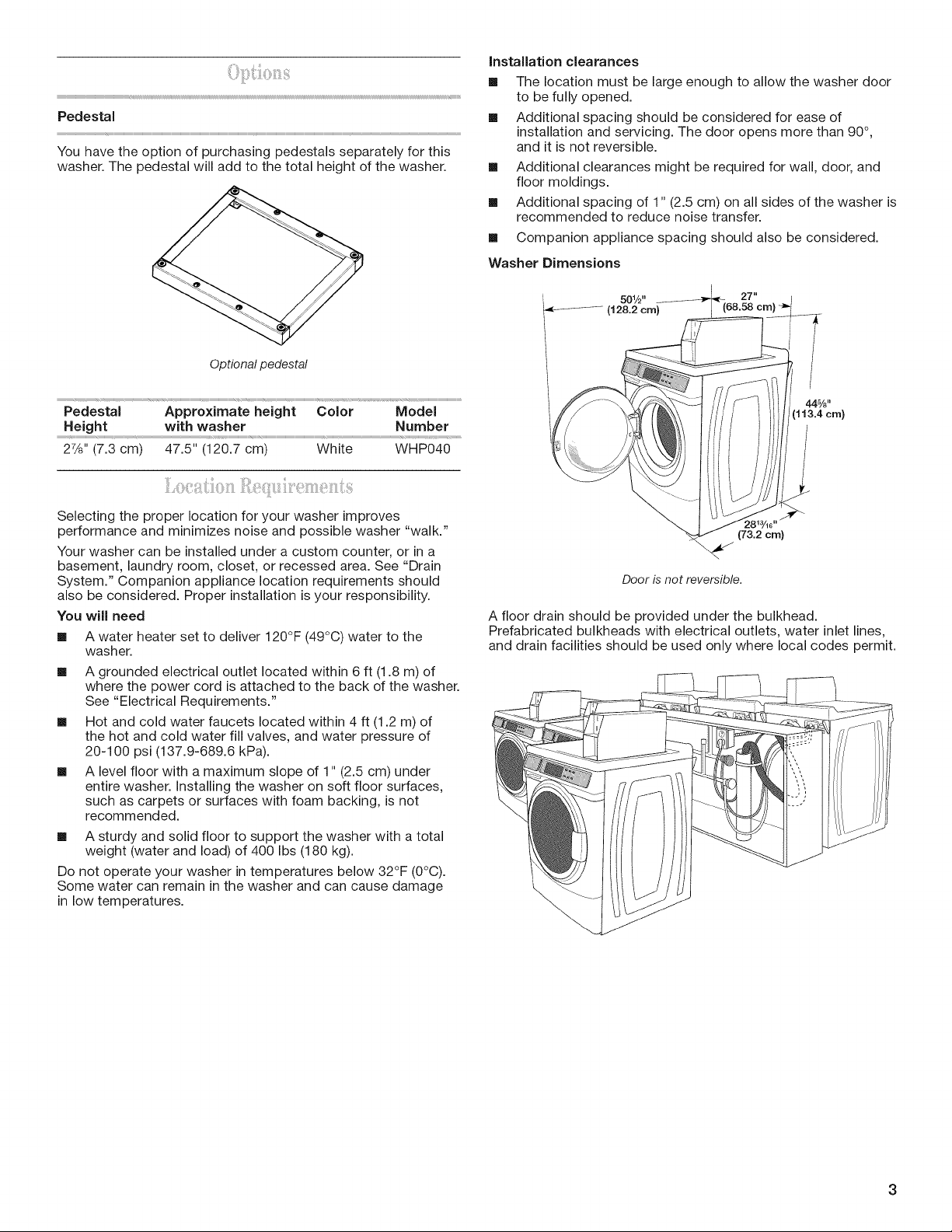
Pedestal
You have the option of purchasing pedestals separately for this
washer. The pedestal will add to the total height of the washer.
Installation clearances
[] The location must be large enough to allow the washer door
to be fully opened.
[] Additional spacing should be considered for ease of
installation and servicing. The door opens more than 90°,
and it is not reversible.
[] Additional clearances might be required for wall, door, and
floor moldings.
[] Additional spacing of 1" (2.5 cm) on all sides of the washer is
recommended to reduce noise transfer.
[]
Companion appliance spacing should also be considered.
Washer Dimensions
501/2" 27"
Optional pedestal
Pedestal Approximate height Color Model
Height with washer Number
22/8'' (7.3 cm) 47.5" (120.7 cm) White WHP040
Selecting the proper location for your washer improves
performance and minimizes noise and possible washer "walk."
Your washer can be installed under a custom counter, or in a
basement, laundry room, closet, or recessed area. See "Drain
System." Companion appliance location requirements should
also be considered. Proper installation is your responsibility.
You will need
[] A water heater set to deliver 120°F (49°C) water to the
washer.
[] A grounded electrical outlet located within 6 ft (1.8 m) of
where the power cord is attached to the back of the washer.
See "Electrical Requirements."
[] Hot and cold water faucets located within 4 ft (1.2 m) of
the hot and cold water fill valves, and water pressure of
20-100 psi (137.9-689.6 kPa).
[] A level floor with a maximum slope of 1" (2.5 cm) under
entire washer. Installing the washer on soft floor surfaces,
such as carpets or surfaces with foam backing, is not
recommended.
[] A sturdy and solid floor to support the washer with a total
weight (water and load) of 400 Ibs (180 kg).
Do not operate your washer in temperatures below 32°F (0°C).
Some water can remain in the washer and can cause damage
in low temperatures.
/
44%"
1113.4 cm}
(73.2 cm)
Door is not reversible.
A floor drain should be provided under the bulkhead.
Prefabricated bulkheads with electrical outlets, water inlet lines,
and drain facilities should be used only where local codes permit.
3

The washer can be installed using the standpipe drain system
(floor or wall), the laundry tub drain system, or the floor drain
system. Select the drain hose installation method you need.
See "Tools and Parts."
Standpipe drain system - wall or floor (views A & B)
The standpipe drain requires a minimum diameter standpipe of
2" (5.0 cm). The minimum carry-away capacity can be no less
than 17 gal. (64 L) per minute.
The top of the standpipe must be at least 30" (76.2 cm) high and
no higher than 96" (2.4 m) from the bottom of the washer.
A B
Laundry tub drain system (view C}
The laundry tub needs a minimum 20 gal. (76 L) capacity.
The top of the laundry tub must be at least 30" (76.2 cm)
above the floor.
Floor drain system (view D}
The floor drain system requires a siphon break that may be
purchased separately. See "Tools and Parts."
The siphon break must be a minimum of 28" (71.0 cm) from
the bottom of the washer. Additional hoses might be needed.
Electrical Shock Hazard
Plug into a grounded 3 prong outlet.
Do not remove ground prong.
Do not use an adapter,
Do not use an extension cord,
Failure to follow these instructions can result in death,
fire, or electrical shock.
[] A 120 volt, 60 Hz., AC only, 15- or 20-amp, fused electrical
supply is required. A time-delay fuse or circuit breaker is
recommended. It is recommended that a separate circuit
serving only this appliance be provided.
[] This washer is equipped with a power supply cord having a
3 prong grounding plug.
[] To minimize possible shock hazard, the cord must be
plugged into a mating, 3 prong, grounding-type outlet,
grounded in accordance with local codes and ordinances.
If a mating outlet is not available, it is the personal
responsibility and obligation of the customer to have the
properly grounded outlet installed by a qualified electrician.
[] If codes permit and a separate ground wire is used, it is
recommended that a qualified electrician determine that the
ground path is adequate.
[] Do not ground to a gas pipe.
[] Check with a qualified electrician if you are not sure the
washer is properly grounded.
[] Do not have a fuse in the neutral or ground circuit.
C D
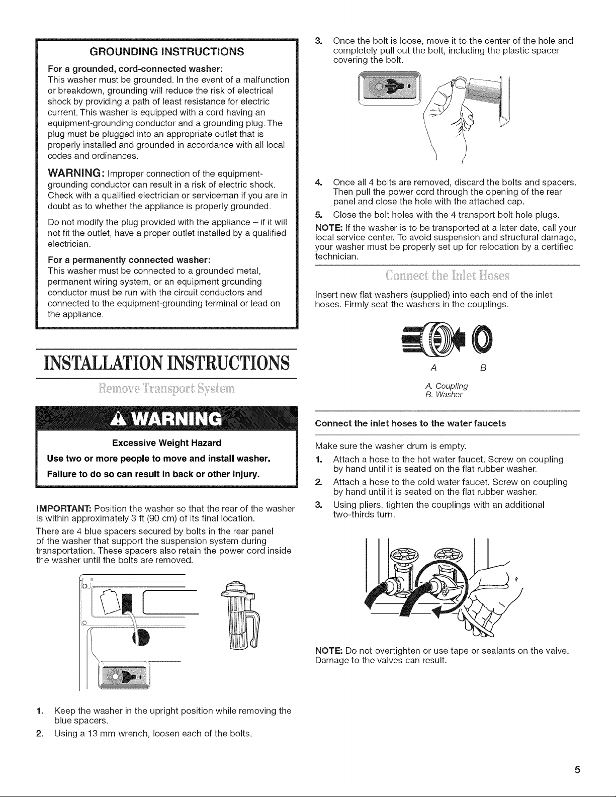
GROUNDING INSTRUCTIONS
For a grounded, cord-connected washer:
This washer must be grounded. In the event of a malfunction
or breakdown, grounding will reduce the risk of electrical
shock by providing a path of least resistance for electric
current. This washer is equipped with a cord having an
equipment-grounding conductor and a grounding plug. The
plug must be plugged into an appropriate outlet that is
properly installed and grounded in accordance with all local
codes and ordinances.
3=
Once the bolt is loose, move it to the center of the hole and
completely pull out the bolt, including the plastic spacer
covering the bolt.
WARNING: Improper connection of the equipment-
grounding conductor can result in a risk of electric shock.
Check with a qualified electrician or serviceman if you are in
doubt as to whether the appliance is properly grounded.
Do not modify the plug provided with the appliance - if it wilt
not fit the outlet, have a proper outlet installed by a qualified
electrician.
For a permanently connected washer:
This washer must be connected to a grounded metal,
permanent wiring system, or an equipment grounding
conductor must be run with the circuit conductors and
connected to the equipment-grounding terminal or lead on
the appliance.
INSTALLATIONINSTRUCTIONS
Excessive Weight Hazard
Use two or more people to move and install washer.
Failure to do so can result in back or other injury.
IMPORTANT: Position the washer so that the rear of the washer
is within approximately 3 ft (90 cm) of its final location.
There are 4 blue spacers secured by bolts in the rear panel
of the washer that support the suspension system during
transportation. These spacers also retain the power cord inside
the washer until the bolts are removed.
4. Once all 4 bolts are removed, discard the bolts and spacers.
Then pull the power cord through the opening of the rear
panel and close the hole with the attached cap.
5. Close the bolt holes with the 4 transport bolt hole plugs.
NOTE: If the washer is to be transported at a later date, call your
local service center. To avoid suspension and structural damage,
your washer must be properly set up for relocation by a certified
technician.
Insert new flat washers (supplied) into each end of the inlet
hoses. Firmly seat the washers in the couplings.
A B
A. Coupling
B. Washer
Connect the inlet hoses to the water faucets
Make sure the washer drum is empty.
1. Attach a hose to the hot water faucet. Screw on coupling
by hand until it is seated on the flat rubber washer.
2. Attach a hose to the cold water faucet. Screw on coupling
by hand until it is seated on the flat rubber washer.
3. Using pliers, tighten the couplings with an additional
two-thirds turn.
1. Keep the washer in the upright position while removing the
blue spacers.
2. Using a 13 mm wrench, loosen each of the bolts.
NOTE: Do not overtighten or use tape or sealants on the valve.
Damage to the valves can result.
5
Clear water lines
[] Run water through both faucets and inlet hoses, into a
laundry tub, drainpipe, or bucket, to get rid of particles
in the water lines that might clog the inlet valve screens.
[] Check the temperature of the water to make sure that the
hot water hose is connected to the hot water faucet and
that the cold water hose is connected to the cold water
faucet.
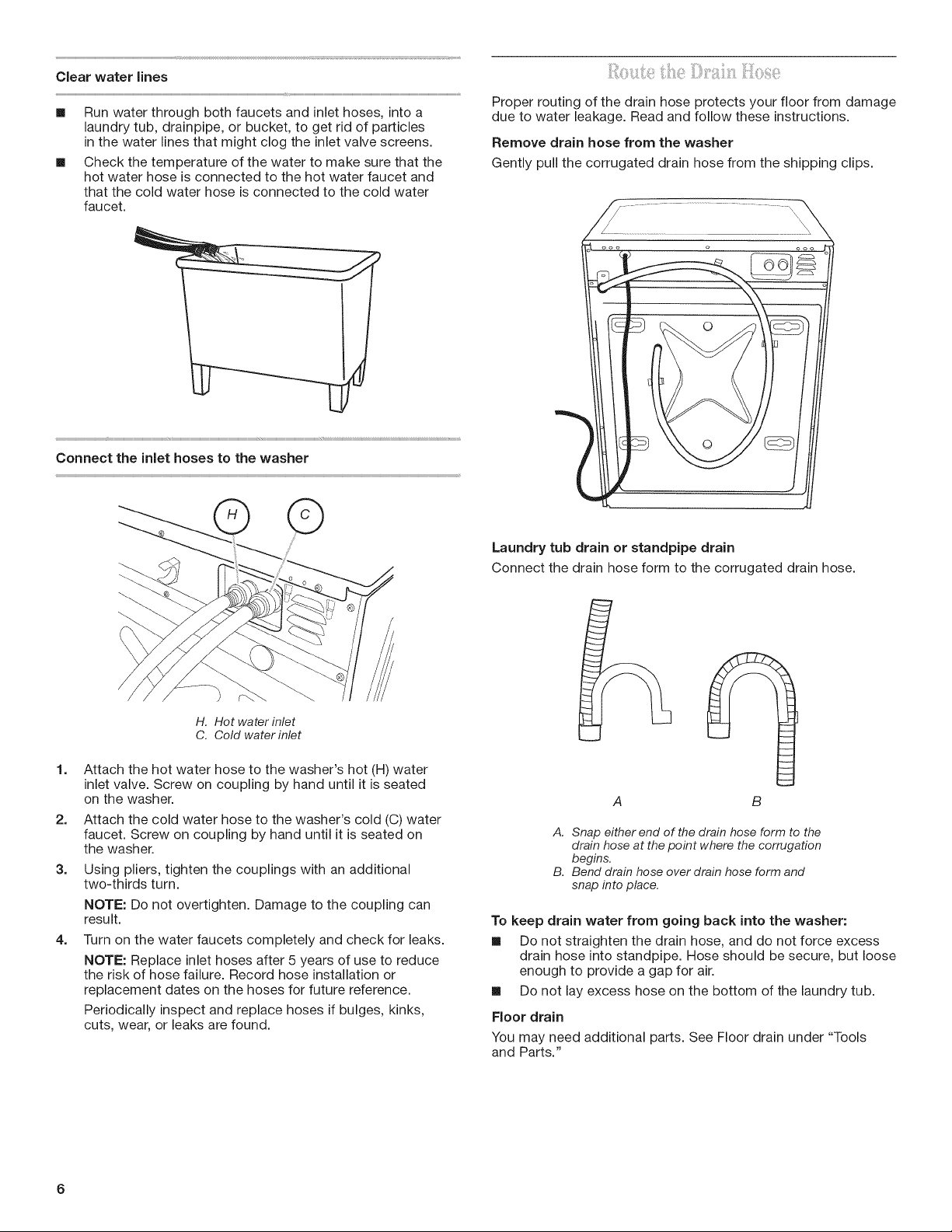
Proper routing of the drain hose protects your floor from damage
due to water leakage. Read and follow these instructions.
Remove drain hose from the washer
Gently pull the corrugated drain hose from the shipping clips.
Laundry tub drain or standpipe drain
Connect the drain hose form to the corrugated drain hose.
H. Hot water inlet
C. Cold water inlet
1=
Attach the hot water hose to the washer's hot (H) water
inlet valve. Screw on coupling by hand until it is seated
on the washer.
2=
Attach the cold water hose to the washer's cold (C) water
faucet. Screw on coupling by hand until it is seated on
the washer.
3=
Using pliers, tighten the couplings with an additional
two-thirds turn.
NOTE: Do not overtighten. Damage to the coupling can
result.
4=
Turn on the water faucets completely and check for leaks.
NOTE: Replace inlet hoses after 5 years of use to reduce
the risk of hose failure. Record hose installation or
replacement dates on the hoses for future reference.
Periodically inspect and replace hoses if bulges, kinks,
cuts, wear, or leaks are found.
B
A. Snap either end of the drain hose form to the
drain hose at the point where the corrugation
begins.
B. Bend drain hose over drain hose form and
snap into place.
To keep drain water from going back into the washer:
[] Do not straighten the drain hose, and do not force excess
drain hose into standpipe. Hose should be secure, but loose
enough to provide a gap for air.
[] Do not lay excess hose on the bottom of the laundry tub.
Floor drain
You may need additional parts. See Floor drain under "Tools
and Parts."
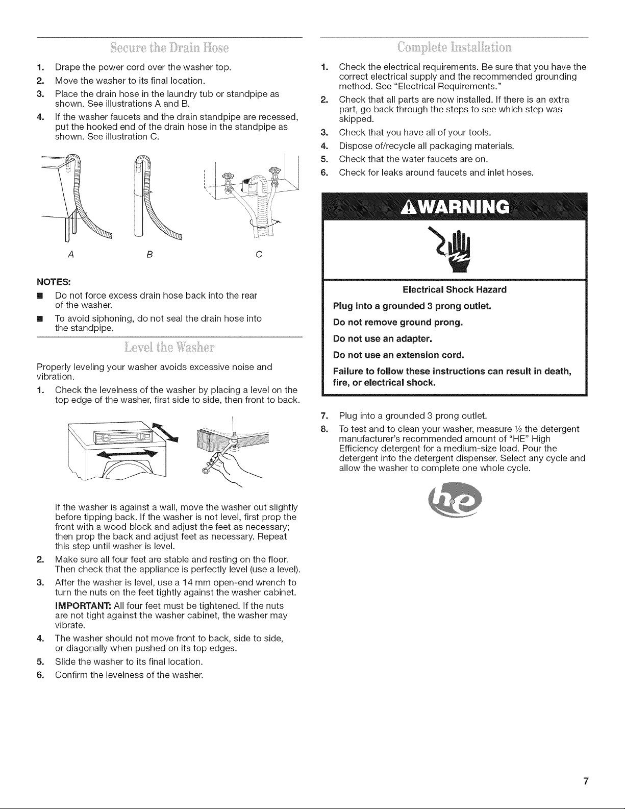
1.
Drape the power cord over the washer top.
2.
Move the washer to its final location.
3.
Place the drain hose in the laundry tub or standpipe as
shown. See illustrations A and B.
4.
If the washer faucets and the drain standpipe are recessed,
put the hooked end of the drain hose in the standpipe as
shown. See illustration C.
!:I
A B C
1.
Check the electrical requirements. Be sure that you have the
correct electrical supply and the recommended grounding
method. See "Electrical Requirements."
2.
Check that all parts are now installed, if there is an extra
part, go back through the steps to see which step was
skipped.
3.
Check that you have all of your tools.
4.
Dispose of/recycle all packaging materials.
5.
Check that the water faucets are on.
6.
Check for leaks around faucets and inlet hoses.
NOTES:
[] Do not force excess drain hose back into the rear
of the washer.
[] To avoid siphoning, do not seal the drain hose into
the standpipe.
Properly leveling your washer avoids excessive noise and
vibration.
1. Check the levelness of the washer by placing a level on the
top edge of the washer, first side to side, then front to back.
If the washer is against a wall, move the washer out slightly
before tipping back. If the washer is not level, first prop the
front with a wood block and adjust the feet as necessary;
then prop the back and adjust feet as necessary. Repeat
this step until washer is level.
2.
Make sure all four feet are stable and resting on the floor.
Then check that the appliance is perfectly level (use a level).
3.
After the washer is level, use a 14 mm open-end wrench to
turn the nuts on the feet tightly against the washer cabinet.
IMPORTANT: All four feet must be tightened. If the nuts
are not tight against the washer cabinet, the washer may
vibrate.
4.
The washer should not move front to back, side to side,
or diagonally when pushed on its top edges.
5.
Slide the washer to its final location.
6.
Confirm the levelness of the washer.
Electrical Shock Hazard
Plug into a grounded 3 prong outlet.
Do not remove ground prong.
Do not use an adapter.
Do not use an extension cord.
Failure to follow these instructions can result in death,
fire, or electrical shock.
7.
Plug into a grounded 3 prong outlet.
8.
To test and to clean your washer, measure 1/2the detergent
manufacturer's recommended amount of "HE" High
Efficiency detergent for a medium-size load. Pour the
detergent into the detergent dispenser. Select any cycle and
allow the washer to complete one whole cycle.
7
SETUPINSTRUCTIONS
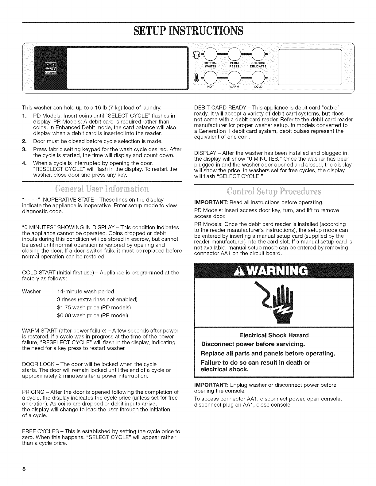
This washer can hold up to a 16 Ib (7 kg) load of laundry.
1. PD Models: insert coins until "SELECT CYCLE" flashes in
display. PR Models: A debit card is required rather than
coins. In Enhanced Debit mode, the card balance will also
display when a debit card is inserted into the reader.
2. Door must be closed before cycle selection is made.
3. Press fabric setting keypad for the wash cycle desired. After
the cycle is started, the time will display and count down.
4. When a cycle is interrupted by opening the door,
"RESELECT CYCLE" will flash in the display. To restart the
washer, close door and press any key.
.... iNOPERATIVE STATE -These lines on the display
indicate the appliance is inoperative. Enter setup mode to view
diagnostic code.
"0 MINUTES" SHOWING IN DISPLAY- This condition indicates
the appliance cannot be operated. Coins dropped or debit
inputs during this condition will be stored in escrow, but cannot
be used until normal operation is restored by opening and
closing the door. If a door switch fails, it must be replaced before
normal operation can be restored.
COLD START (initial first use) - Appliance is programmed at the
factory as follows:
DEBIT CARD READY - This appliance is debit card "cable"
ready. It will accept a variety of debit card systems, but does
not come with a debit card reader. Refer to the debit card reader
manufacturer for proper washer setup. In models converted to
a Generation 1 debit card system, debit pulses represent the
equivalent of one coin.
DISPLAY - After the washer has been installed and plugged in,
the display will show "0 MINUTES." Once the washer has been
plugged in and the washer door opened and closed, the display
will show the price. In washers set for free cycles, the display
will flash "SELECT CYCLE."
IMPORTANT: Read all instructions before operating.
PD Models: Insert access door key, turn, and lift to remove
access door.
PR Models: Once the debit card reader is installed (according
to the reader manufacturer's instructions), the setup mode can
be entered by inserting a manual setup card (supplied by the
reader manufacturer) into the card slot. If a manual setup card is
not available, manual setup mode can be entered by removing
connector AA1 on the circuit board.
Washer
WARM START (after power failure) - A few seconds after power
is restored, if a cycle was in progress at the time of the power
failure, "RESELECT CYCLE" will flash in the display, indicating
the need for a key press to restart washer.
DOOR LOCK - The door will be locked when the cycle
starts. The door will remain locked until the end of a cycle or
approximately 2 minutes after a power interruption.
PRiCiNG -After the door is opened following the completion of
a cycle, the display indicates the cycle price (unless set for free
operation). As coins are dropped or debit inputs arrive,
the display will change to lead the user through the initiation
of a cycle.
FREE CYCLES - This is established by setting the cycle price to
zero. When this happens, "SELECT CYCLE" will appear rather
than a cycle price.
14-minute wash period
3 rinses (extra rinse not enabled)
$1.75 wash price (PD models)
$0.00 wash price (PR model)
Electrical Shock Hazard
Disconnect power before servicing.
Replace all parts and panels before operating.
FaUure to do so can result in death or
electrical shock.
iMPORTANT: Unplug washer or disconnect power before
opening the console.
To access connector AA1, disconnect power, open console,
disconnect plug on AA1, close console.

Electrical Shock Hazard
Plug into a grounded 3 prong outlet.
Do not remove ground prong.
Do not use an adapter.
Do not use an extension cord.
Failure to fo{iow these instructions can result in death,
fire, or electrica{ shock.
Plug in washer or reconnect power. The washer is now in the
setup mode.
The temperature keypads and the digital display are used to set
up the controls.
The display can contain 4 numbers and/or letters and a decimal
point. These are used to indicate the setup codes and related
code values available for use in programming the appliance.
HOW TO USE THE KEYPADS TO PROGRAM
THE CONTROLS
1. The HOT keypad is used to adjust the values associated
with setup codes. Pressing the keypad will change the value
by increments. Rapid adjustment is possible by holding the
keypad down.
2. The WARM keypad will advance you through the setup
codes. Pressing the keypad will advance you to the
next available setup code. Holding the keypad down will
automatically advance through the setup codes at a rate
of one per second.
3. The COLD keypad is used to select or deselect options.
Before proceeding, it is worth noting that, despite all of the
options available, an owner can simply choose to un-crate a
new commercial washer, hook it up, plug it in, and have a unit
that operates.
Units are preset at the factory for a 14-minute wash period and
3 rinses (no extra rinse).
SETUP CODES
The WARM keypad will advance you from code to code. The
HOT keypad will change the code value. The COLD keypad will
select or deselect options.
FOR PR MODELS: The setup codes are the same as for the
"PD" model except where noted.
The setup code is indicated by the one or two left-hand
characters. The setup code value is indicated by the two or
three right-hand characters.
CODE EXPLANATION
607 6 REGULAR CYCLE PRICE
07 Represents the number of quarters (coin 1);
may adjust from 0-39. (See VALUE OF COIN 1.)
Advance from 0-39 by pressing HOT.
Currently set for 7 quarters = $1.75.
PR MODEL ONLY: Currently set for 0 quarters.
PS MODEL ONLY: Represents the number of
push-in actuations of the coin slide to start the
washer.
601 setting would represent one coin slide
actuation.
Press WARM keypad once to advance
to next code.
800 8 ADDITIONAL RINSE OPTION
This option is either SELECTED "ON" or NOT
SELECTED "OFR"
00 Not Selected "OFR"
Ar Selected "ON."
Press COLD keypad once for this selection.
Press WARM keypad once to advance
to next code.
900 9 CYCLE COUNTER OPTION
This option is either SELECTED "ON" or NOT
SELECTED "OFR"
00 Not Selected "OFR"
0C Selected "ON" and not able to be deselected.
Press COLD keypad 3 consecutive times to
select "ON." Once selected "ON" it cannot be
deselected.
Press WARM keypad once to advance
to next code.
This option is either SELECTED "ON" or NOT
SELECTED "OFR"
00 Not Selected "OFR"
0C Selected "ON."
Press COLD keypad 3 consecutive times to select
"ON" and 3 consecutive times to remove (Not
Selected "OFF"). Counter resets by going from
"OFF" to "ON."
Press WARM keypad once to advance
to next code.
CO Selected "ON" and not able to be deselected.
To select "ON" and not able to be deselected, first
select "ON," then within 2 seconds, press COLD
twice, HOT once, and exit setup mode.
2.00 2. SPECIAL PRICING OPTIONS
This option is either SELECTED "ON" or NOT
SELECTED "OFF."
00 Not Selected "OFR"
SP Selected "ON."
Press COLD keypad once for this selection.
If SPECIAL PRICING OPTION is selected, you have access
to codes 3.XX through 9.XX.
Press WARM keypad once to advance to next code.
9
Options to use if SPECIAL PRiCiNG is selected.
When exiting setup code "9.", it must show current day
of week.
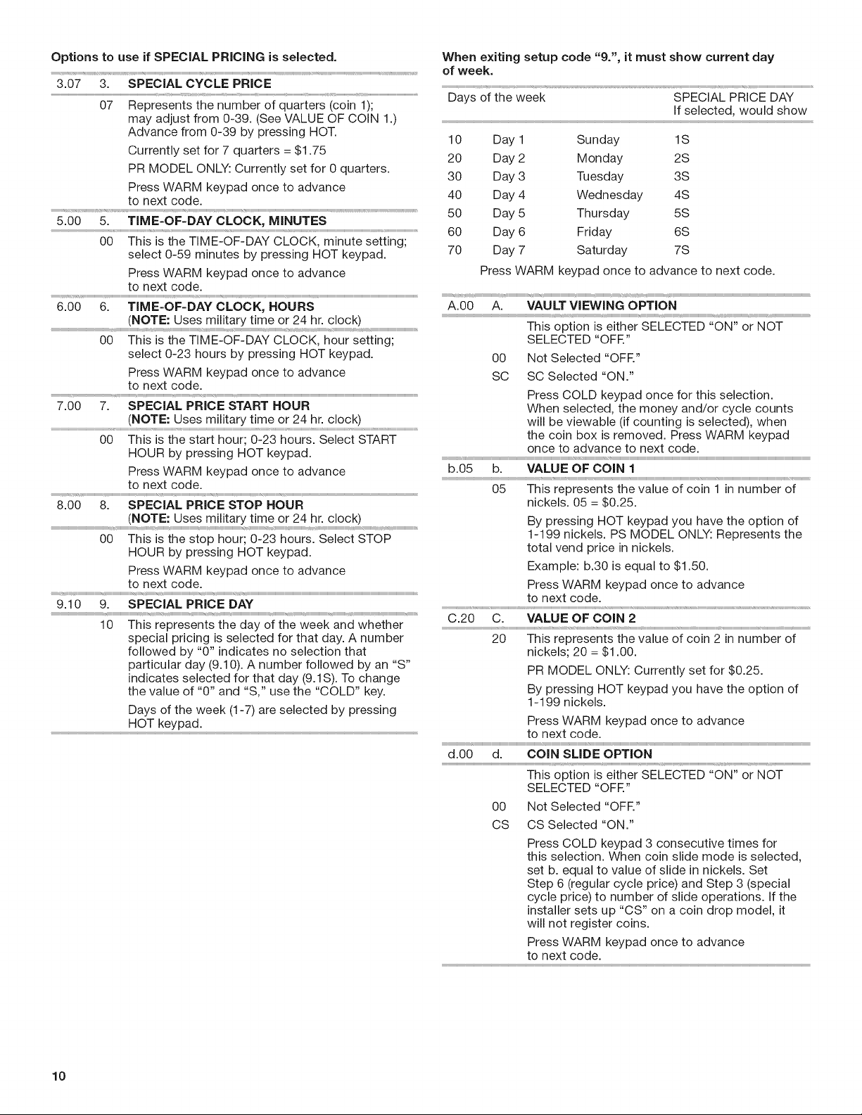
3.07 3. SPECIAL CYCLE PRICE
07 Represents the number of quarters (coin 1);
may adjust from 0-39. (See VALUE OF COiN 1.)
Advance from 0-39 by pressing HOT.
Currently set for 7 quarters = $1.75
PR MODEL ONLY: Currently set for 0 quarters.
Press WARM keypad once to advance
to next code.
5.00 5. TIME-OF-DAY CLOCK, MINUTES
00 This is the TIME-OF-DAY CLOCK, minute setting;
select 0-59 minutes by pressing HOT keypad.
Press WARM keypad once to advance
Days of the week SPECIAL PRICE DAY
If selected, would show
10 Day 1 Sunday 1S
20 Day 2 Monday 2S
30 Day 3 Tuesday 3S
40 Day 4 Wednesday 4S
50 Day 5 Thursday 5S
60 Day 6 Friday 6S
70 Day 7 Saturday 7S
Press WARM keypad once to advance to next code.
to next code.
6.00 6. TIME-OF-DAY CLOCK, HOURS
(NOTE: Uses military time or 24 hr. clock)
00 This is the TIME-OF-DAY CLOCK, hour setting;
select 0-23 hours by pressing HOT keypad.
Press WARM keypad once to advance
:::::::::::::::::::::::::: _',_HHHH_HHHHHHHHHHHHHHHHHH_r_,_HHHHHHHHH_r,,,__HHHH_HHHHHHHHHHH_HHHHHHHHHHHHHH_r_HHHHHHHHHHHHHHHHHHHHHHHHHHHHHHHHHHHHHHHHHHHHHHHHHHHHHHHHHHHHHHHHHHHHHHHHHHHHHHHHHHHHHHHHHHHHHHHHHHHHHHHHHHHHHHHHHHH_
to next code.
7.00 7. SPECIAL PRICE START HOUR
(NOTE: Uses military time or 24 hr. clock)
........................................................................................................ r
00 This is the start hour; 0-23 hours. Select START
HOUR by pressing HOT keypad.
Press WARM keypad once to advance
r i r r r r r r r r r r_ ........................................................................................................................................................................
to next code.
8.00 8. SPECIAL PRICE STOP HOUR
(NOTE: Uses military time or 24 hr. clock)
00 This is the stop hour; 0-23 hours. Select STOP
HOUR by pressing HOT keypad.
Press WARM keypad once to advance
to next code.
9.10 9. SPECIAL PRICE DAY
10 This represents the day of the week and whether
special pricing is selected for that day. A number
followed by "0" indicates no selection that
particular day (9.10). A number followed by an "S"
indicates selected for that day (9.1S). To change
the value of "0" and "S," use the "COLD" key.
Days of the week (1-7) are selected by pressing
A.00 A. VAULT VIEWING OPTION
This option is either SELECTED "ON" or NOT
SELECTED "OFR"
O0 Not Selected "OFR"
SC SC Selected "ON."
Press COLD keypad once for this selection.
When selected, the money and/or cycle counts
will be viewable (if counting is selected), when
the coin box is removed. Press WARM keypad
once to advance to next code.
b.05 b. VALUE OF COIN 1
05 This represents the value of coin 1 in number of
nickels. 05 = $0.25.
By pressing HOT keypad you have the option of
1-199 nickels. PS MODEL ONLY: Represents the
total vend price in nickels.
Example: b.30 is equal to $1.50.
Press WARM keypad once to advance
to next code.
C.20 C. VALUE OF COIN 2
20 This represents the value of coin 2 in number of
nickels; 20 = $1.00.
PR MODEL ONLY: Currently set for $0.25.
By pressing HOT keypad you have the option of
1-199 nickels.
HOT keypad.
10
O0 Not Selected "OFR"
CS CS Selected "ON."
Press COLD keypad 3 consecutive times for
this selection. When coin slide mode is selected,
set b. equal to value of slide in nickels. Set
Step 6 (regular cycle price) and Step 3 (special
cycle price) to number of slide operations, if the
installer sets up "CS" on a coin drop model, it
will not register coins.
Press WARM keypad once to advance
to next code.
 Loading...