

Page 1
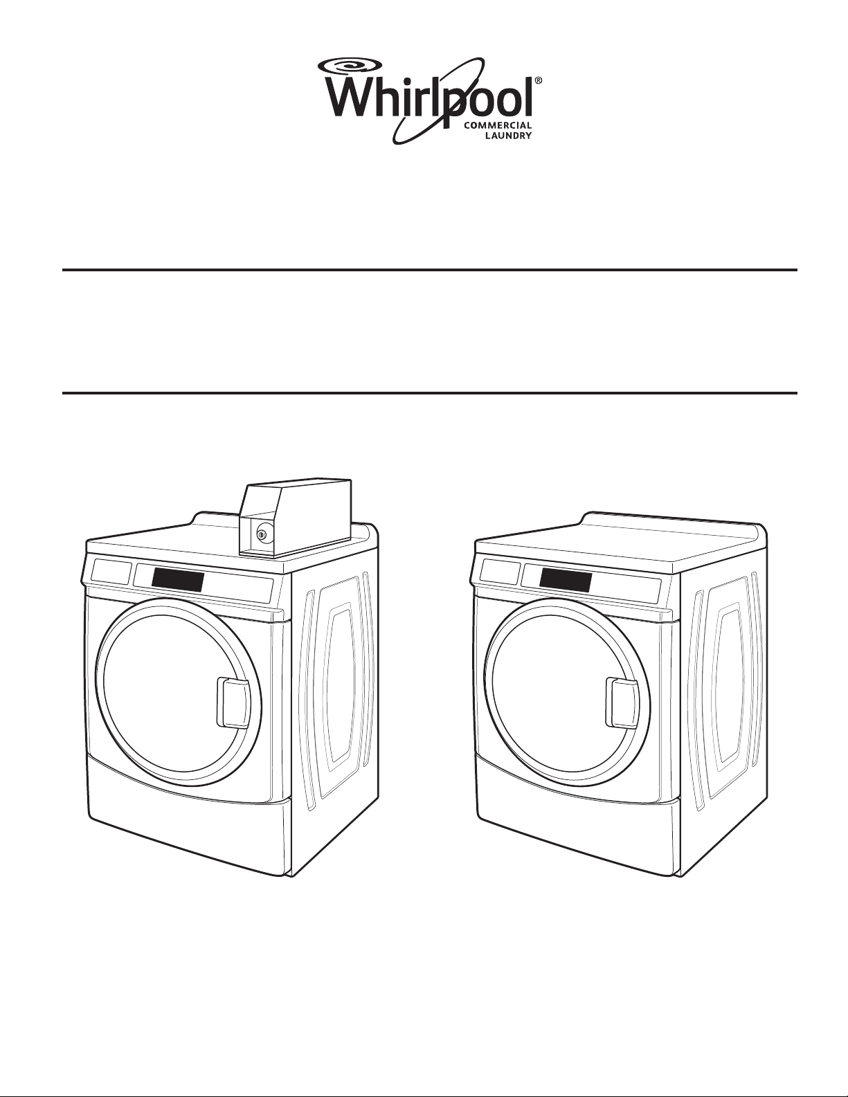
INSTALLATION INSTRUCTIONS
Commercial Dryer Gas or Electric
INSTRUCTIONS D’INSTALLATION
Sécheuse à usage commercial
à gaz ou électrique
W10919522B
W10919523B—SP
www.whirlpoolcommerciallaundry.com
Page 2
TABLE OF CONTENTS
Page
DRYER SAFETY ....................................................................... 2
INSTALLATION REQUIREMENTS ........................................... 5
Tools and Parts .................................................................... 5
Dimensions/Clearances ...................................................... 6
Venting Requirements ........................................................ 7
Gas Dryer Installation Requirements ................................ 10
Electric Dryer Installation Requirements ........................... 14
INSTALLING LEVELING LEGS, COIN SLIDE,
AND COIN BOX ..................................................................... 17
INSTALLATION INSTRUCTIONS – GAS DRYER .................. 18
Make Gas Connection ...................................................... 18
INSTALLATION INSTRUCTIONS – ELECTRIC DRYER ....... 19
Electric Dryer Electrical Connections ............................... 19
LEVELING .............................................................................. 24
COMPLETE INSTALLATION ................................................. 24
REVERSING DRYER DOOR SWING .................................... 25
MAINTENANCE INSTRUCTIONS ......................................... 27
IF YOU NEED ASSISTANCE ................................................. 27
ELECTRONIC CONTROL SETUP INSTRUCTIONS ........... 28
WARRANTY .......................................................................... 34
TABLE DES MATIÈRES
Page
SÉCURITÉ DE LA SÉCHEUSE .............................................. 35
EXIGENCES D’INSTALLATION ............................................. 38
Outils et pièces .................................................................. 38
Dimensions/Distances de dégagement ............................. 39
Exigences concernant l’évacuation ................................... 40
Exigences d’installation pour la sécheuse à gaz ................ 43
Exigences d’installation pour la sécheuse électrique ........ 47
INSTALLATION DES PIEDS DE NIVELLEMENT,
DE LA GLISSIÈRE À MONNAIE ET DE LA CAISSE
À MONNAIE ........................................................................... 49
INSTRUCTIONS D’INSTALLATION
POUR LA SÉCHEUSE À GAZ ................................................ 50
Raccordement à la canalisation de gaz ............................. 50
NIVELLEMENT .......................................................................51
ACHEVER L’INSTALLATION ................................................. 52
INVERSION DU SENS D’OUVERTURE
DE LA PORTE DE LA SÉCHEUSE ........................................53
INSTRUCTIONS D’ENTRETIEN ............................................55
SI VOUS AVEZ BESOIN D’ASSISTANCE ..............................55
INSTRUCTIONS DE RÉGLAGE DU TABLEAU
DE COMMANDE ÉLECTRONIQUE ...................................... 56
GARANTIE ............................................................................. 63
DRYER SAFETY
■ It is recommended that the owner post, in a prominent location, instructions for the customer’s use in the event the customer
smells gas. This information should be obtained from your gas supplier.
■ Post the following warning in a prominent location.
2
Page 3
DRYER SAFETY
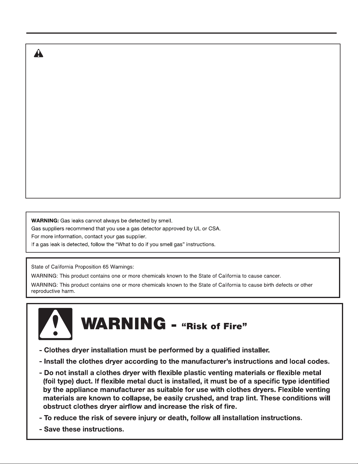
WARNING:
FIRE OR EXPLOSION HAZARD
Failure to follow safety warnings exactly could result in serious injury, death, or property
damage.
–
Do not store or use gasoline or other ammable vapors and liquids in the vicinity of this
or any other appliance.
–
WHAT TO DO IF YOU SMELL GAS:
Do not try to light any appliance.
•
Do not touch any electrical switch; do not use any phone in your building.
•
Clear the room, building, or area of all occupants.
•
Immediately call your gas supplier from a neighbor’s phone. Follow the gas supplier’s
•
instructions.
If you cannot reach your gas supplier, call the re department.
•
–
Installation and service must be performed by a qualied installer, service agency, or
the gas supplier.
3
Page 4
DRYER SAFETY
IMPORTANT: The gas installation must conform with local codes, or in the absence of local codes, with the National Fuel Gas
Code, ANSI Z223.1/NFPA 54, or the Natural Gas and Propane Installation Code, CSA B149.1.
The dryer must be electrically grounded in accordance with local codes, or in the absence of local codes, with the National
Electrical Code, ANSI/NFPA 70, or the Canadian Electrical Code, Part 1, CSA C22.1.
4
Page 5
INSTALLATION REQUIREMENTS
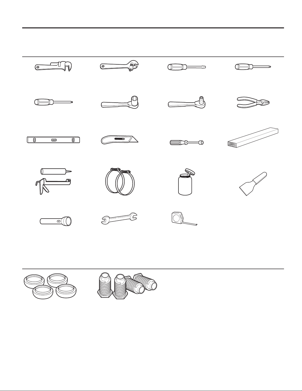
Tools and Parts
Tools Needed:
8" (200 mm) 8" (200 mm) or 10" (250 mm) Flat-Blade Screwdriver Phillips Screwdriver
or 10" (250 mm) Adjustable Wrench
Pipe Wrench that opens to 1" (25 mm)
TORX® T-20®† Security 1" (25 mm) Hex-Head 1⁄4" Socket Wrench Pliers (that open to
Screwdriver or Bit Socket Wrench 19/16" [39 mm])
Level Utility Knife 1/4" (6 mm) Nut Driver 27" (686 mm)
Wood Block
Caulk Gun and Caulk Vent Clamps Pipe-Joint Compound Putty Knife
(for installing new exhaust vent) suitable for gas type
Flashlight (optional) 1" (25 mm) Ruler or Measuring Tape
Open-End Wrenches
Parts Supplied:
Foot Boots (4) Leveling Legs (4)
To locate factory specied replacement parts in your area,
contact the dealer from whom you purchased your dryer.
†®TORX and T20 are registered trademarks of Acument Intellectual Properties, LLC.
5
Page 6
INSTALLATION REQUIREMENTS
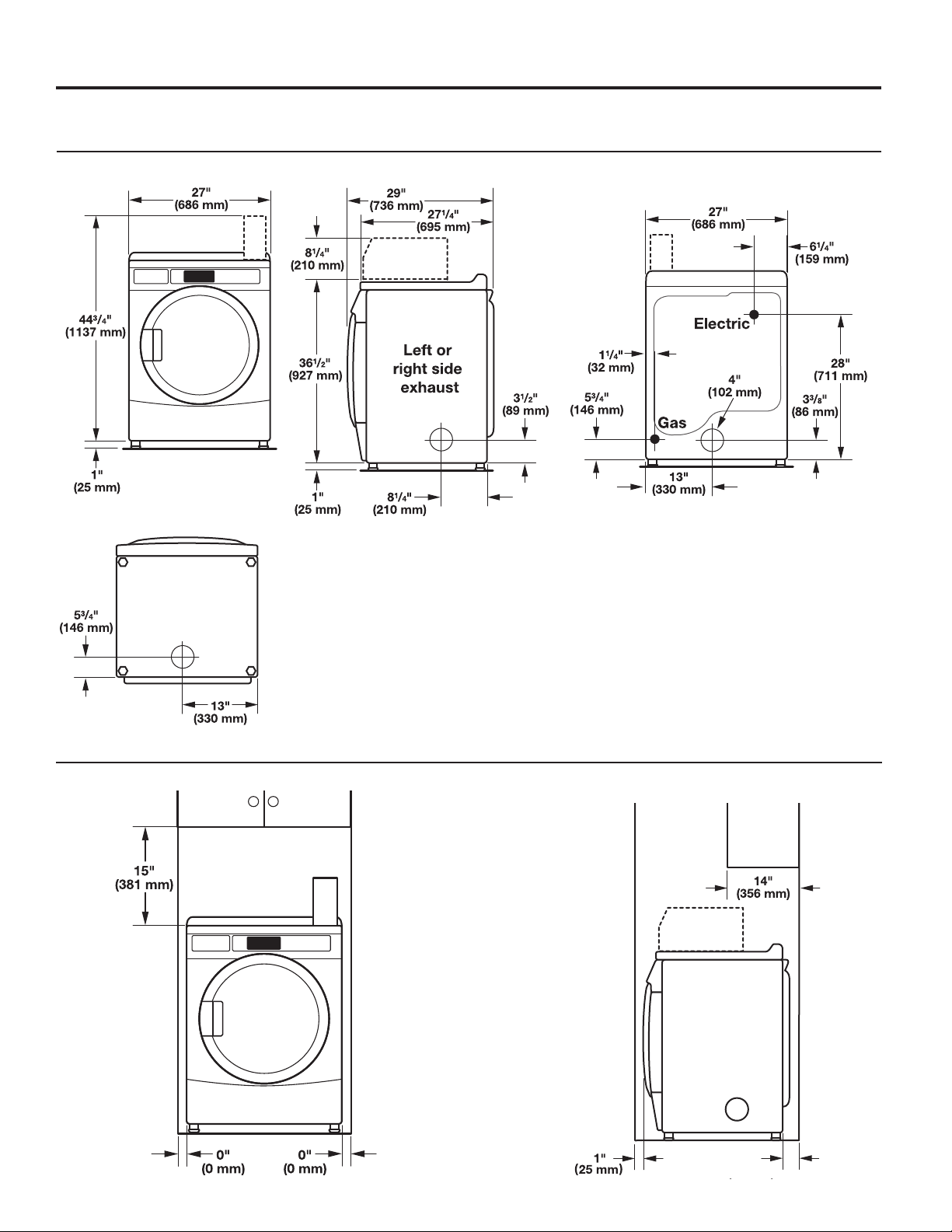
Dimensions/Clearances
Dimensions
Front View Side View Back View
Bottom Exhaust
Clearances
Recessed Front View Closet Side View
6
0"
(0 mm)
Page 7
INSTALLATION REQUIREMENTS
Venting Requirements
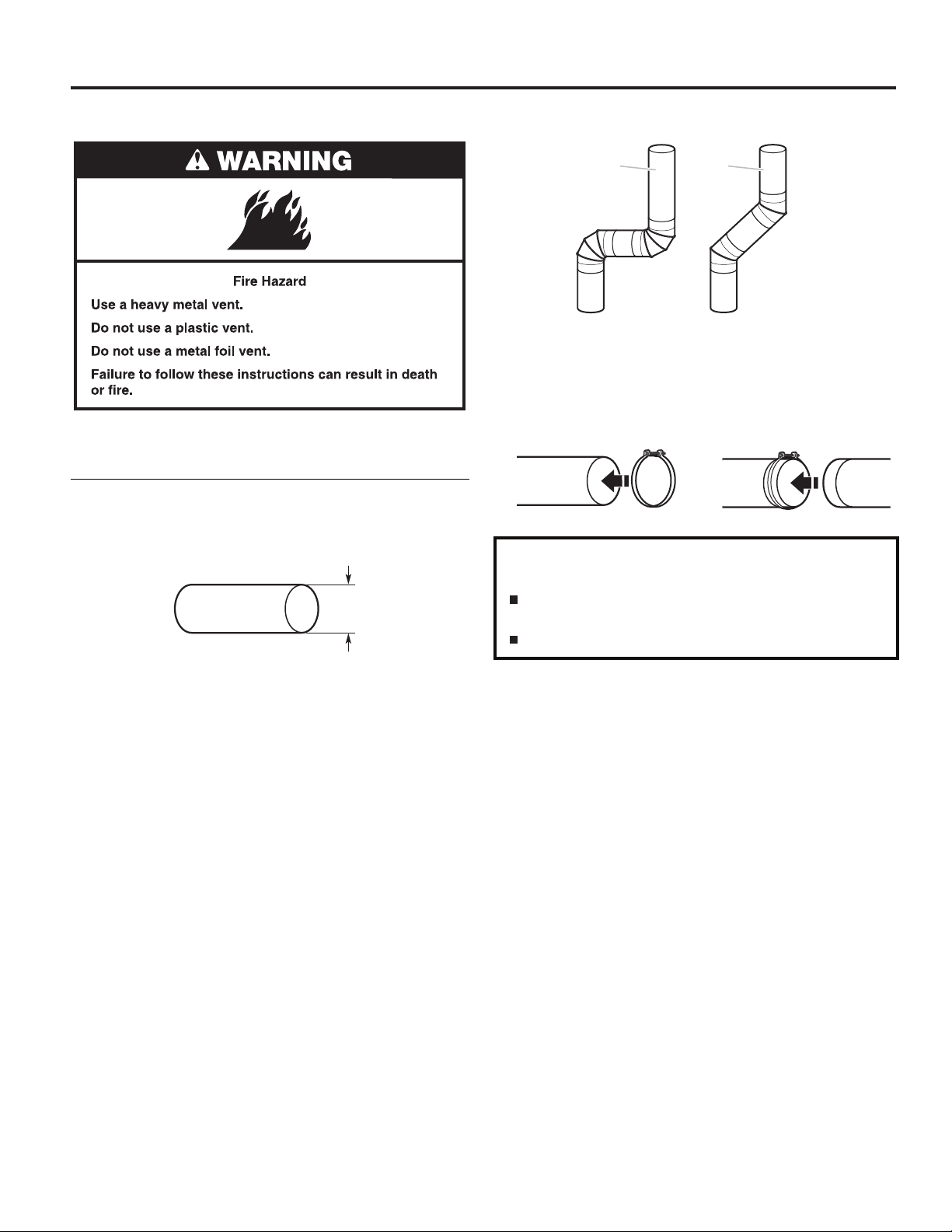
WARNING: To reduce the risk of re, this dryer MUST BE
EXHAUSTED OUTDOORS.
IMPORTANT: Observe all governing codes and ordinances.
Dryer exhaust must not be connected into any gas vent,
chimney, wall, ceiling, attic, crawlspace, or a concealed space
of a building. Only rigid or exible metal vent shall be used for
exhausting.
4"
(102 mm)
4" (102 mm) heavy, metal exhaust vent
Elbows:
■ 45° elbows provide better airow than 90° elbows.
Good
Better
Clamps:
■ Use clamps to seal all joints.
■ Exhaust vent must not be connected or secured with screws
or other fastening devices that extend into interior of duct
and catch lint. Do not use duct tape.
Improper venting can cause moisture and lint to collect
indoors, which may result in:
Moisture damage to woodwork, furniture, paint, wallpaper,
carpets, etc.
Housecleaning problems and health problems.
■ Only a 4" (102 mm) heavy, metal exhaust vent and clamps
may be used.
■ Do not use plastic or metal foil vent.
Rigid metal vent:
■ Recommended for best drying performance and to avoid
crushing and kinking.
Flexible metal vent: (Acceptable only if accessible to clean)
■ Must be fully extended and supported in nal dryer location.
■ Remove excess to avoid sagging and kinking that may result
in reduced airow and poor performance.
■ Do not install in enclosed walls, ceilings, or oors.
■ The total length should not exceed 7
3
⁄4 ft. (2.4 m).
NOTE: If using an existing vent system, clean lint from entire
length of the system and make sure exhaust hood is not
plugged with lint. Replace plastic or metal foil vents with rigid
metal or exible metal vents. Review “Vent System Chart” and
if necessary, modify existing vent system to achieve best drying
performance.
NOTE: Although each single-load dryer should typically have
an unobstructed outdoor air opening of 24" (154 cm) (based
on 1" [6.5 cm] per 1,000 Btu [252 kcal]), common make-up air
openings are also acceptable.
Set up common openings so the make-up air is distributed
equally to all dryers. Coverage area must be increased by 33%
to account for the use of registers or louvers.
Make-up air openings should not be installed near the building
exits for exhaust vents.
7
Page 8
INSTALLATION REQUIREMENTS
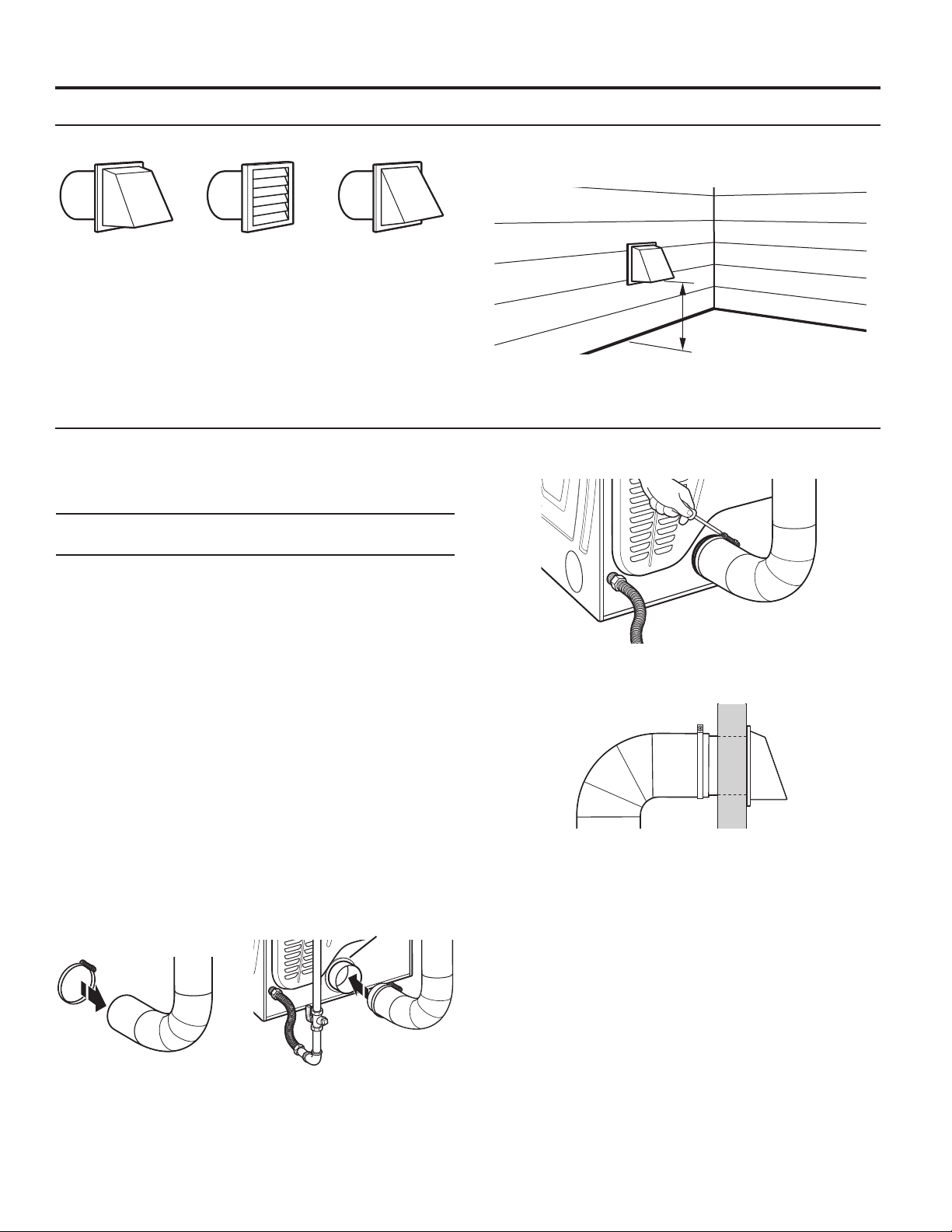
Vent Hoods
4" (102 mm) Diameter Exhaust Hoods
Box Hood Louvered Hood Angled Hood
Vent System Length
Maximum Vent Length/Vent Connection
Maximum length of vent system depends upon the type of vent
used, number of elbows, and type of exhaust hood.
Vent System Chart (Rigid Metal Vent)
No. of
90˚ Turns
0 64 ft. (19.5 m) 58 ft. (17.7 m)
1 54 ft. (16.5 m) 48 ft. (14.6 m)
2 44 ft. (13.4 m) 38 ft. (11.6 m)
3 35 ft. (10.7 m) 29 ft. (8.8 m)
4 27 ft. (8.2 m) 21 ft. (6.4 m)
For vent systems not covered by the vent specication chart,
see your parts distributor.
Provision must be made for enough air for combustion
and ventilation. (Check governing codes and ordinances.)
See “Recessed Area and Closet Installation Instructions”
in the “Location Requirements” sections.
A 4" (102 mm) outlet hood is preferred. However, a 21⁄2"
(64 mm) outlet exhaust hood may be used. A 21⁄2" (64 mm)
outlet creates greater back pressure than other hood types.
For permanent installation, a stationary vent system is required.
Connect Vent
1. If connecting to existing vent, make sure the vent is clean.
2. Using a 4" (102 mm) clamp, connect vent to exhaust outlet
in dryer.
Box and
Louvered Hood
Angled Hood
Vent collar
Exhaust hood must be at least 12" (305 mm) from the ground
or any object that may be in the path of the exhaust (such as
owers, rocks, bushes, or snow).
12" min.
(305 mm)
3. Tighten hose clamp with Phillips screwdriver.
4. Make sure the vent is secured to exhaust hood with
a 4" (102 mm) clamp.
5. Move dryer into nal position. Do not crush or kink vent.
Make sure dryer is level.
NOTE: Do not remove vent collar.
8
Page 9

INSTALLATION REQUIREMENTS
If an Exhaust Hood Cannot be Used Multiple Dryer Venting
The outside end of main vent should have a sweep elbow
directed downward.
24" min.
12" min.
(305 mm)*
* Minimum clearance above
any accumulation of snow,
ice, or debris such as leaves
(610 mm)
If main vent travels vertically through the roof, rather than
through wall, install a 180° sweep elbow on end of vent at least
2 ft. (610 mm) above surface of roof.
The opening in wall or roof shall have a diameter 1/2" (13 mm)
larger than vent diameter. Vent should be centered in opening.
Do not install screening over end of vent for best performance.
A main vent can be used for venting a group of dryers. The
main vent should be sized to remove 5663 l/min. (200 CFM)
of air per dryer. Large-capacity lint screens of proper design
may be used in main vent if checked and cleaned frequently.
The room where the dryers are located should have make-up
air equal to or greater than CFM of all the dryers in the room.
Back-draft Damper Kit is available from your distributor and
should be installed in the vent of each dryer to keep exhausted
air from returning into dryers and to keep exhaust in balance
within main vent. Unobstructed return air openings are required.
Each vent should enter the main vent at an angle pointing in
the direction of the airow. Vents entering from the opposite
side should be staggered to reduce the exhausted air from
interfering with the other vents.
30˚ max.
Airflow
Air ow
The maximum angle of each vent entering the main vent should
be no more than 30°.
Keep air openings free of dry cleaning uid fumes. Fumes
create acids which, when drawn through the dryer heating
units, can damage dryers and items being dried.
A clean-out cover should be located on the main vent
for periodic cleaning of the vent system.
9
Page 10
INSTALLATION REQUIREMENTS
(155 cm
Gas Dryer Installation Requirements
Location Requirements
Your dryer can be installed in a basement, laundry room,
or recessed area.
This dryer is not intended for installation in a mobile home.
Companion appliance location requirements should also be
considered.
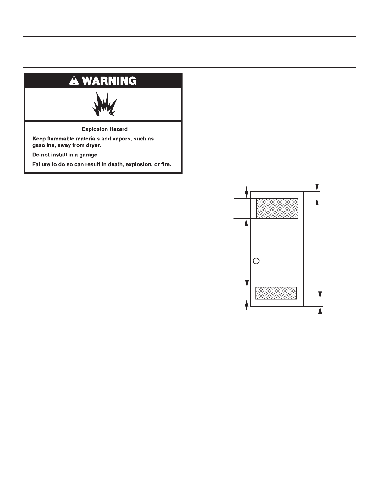
IMPORTANT: Do not install or store the dryer where it will be
exposed to water and/or the weather. Proper installation is your
responsibility.
You will need:
■ A grounded electrical outlet located within 6 ft. (1.8 m) of
where the power cord is attached to the back of the dryer.
See “Electrical Requirements.”
■ A level oor with a maximum slope of 1" (25 mm) under
entire dryer. Installing the dryer on soft oor surfaces,
such as carpets or surfaces with foam backing, is not
recommended.
Gas dryer installation clearances
■ The location must be large enough to allow the dryer door
to be fully opened.
■ Additional spacing should be considered for ease of
installation and servicing. The door opens more than 180°.
■ Additional clearances might be required for wall, door,
and oor moldings.
■ Additional spacing of 1" (25 mm) on all sides of the dryer
is recommended to reduce noise transfer.
When installing a gas dryer:
IMPORTANT: Observe all governing codes and ordinances.
■ Check code requirements: Some codes limit or do not
permit installation of clothes dryers in garages, closets,
or sleeping quarters. Contact your local building inspector.
■ Make sure that lower edges of the cabinet, plus the back
and bottom sides of the dryer, are free of obstructions to
permit adequate clearance of air openings for combustion
air. See “Recessed Area and Closet Installation Instructions”
below for minimum spacing requirements.
Recessed Area and Closet Installation Instructions
This dryer may be installed in a recessed area or closet. For
recessed area and closet installations, minimum clearances
can be found on the warning label on the rear of the dryer
or in “Dimensions/Clearances.”
The installation spacing is in inches and is the minimum
allowable. Additional spacing should be considered for ease
of installation, servicing, and compliance with local codes
and ordinances.
If closet door is installed, the minimum unobstructed air
opening in the top and bottom is required. Louvered doors
with equivalent air openings are acceptable.
The dryer must be exhausted outdoors.
No other fuel-burning appliance may be installed in the same
closet as the dryer.
2
48 in.
(310 cm2)
Front
Front
View
View
2
24 in.
2
Closet
Closet
Door
door
)
3"
(76 mm)
3"
(76 mm)
10
Page 11
Electrical Requirements
IMPORTANT: The dryer must be electrically grounded in
accordance with local codes and ordinances or, in the absence
of local codes, with the National Electrical Code, ANSI/NFPA
70, latest edition, or Canadian Electrical Code, CSA C22.1.
If codes permit and a separate ground wire is used, it is
recommended that a qualied electrical installer determine
that the ground path is adequate.
A copy of the above code standards can be obtained from:
National Fire Protection Association
One Batterymarch Park, Quincy, MA 02269
CSA International
8501 East Pleasant Valley Road
Cleveland, Ohio 44131-5575
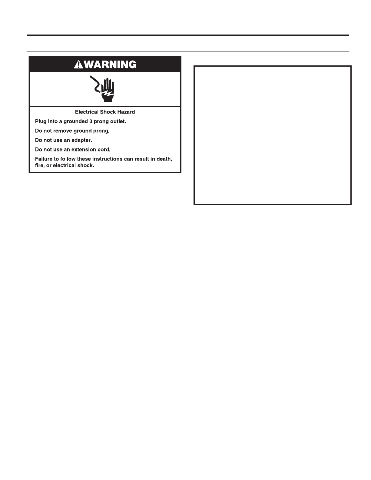
■ Do not ground to a gas pipe.
■ Do not have a fuse in the neutral or ground circuit.
■ A 120-volt, 60 Hz, AC-only, 15- or 20-amp, fused electrical
circuit is required. A time-delay fuse or circuit breaker is also
recommended. It is recommended that a separate circuit
serving only this dryer be provided.
■ This dryer is equipped with a power supply cord having
a 3 prong grounding plug.
■ To minimize the possibility of shock, the cord must be
plugged into a mating, 3 prong, grounding-type outlet,
grounded in accordance with local codes and ordinances.
If a mating outlet is not available, it is the personal
responsibility and obligation of the customer to have the
properly grounded outlet installed by a qualied electrician.
■ If codes permit and a separate ground wire is used, it is
recommended that a qualied electrician determine that
the ground path is adequate.
■ Check with a qualied electrician if you are not sure
the dryer is properly grounded.
INSTALLATION REQUIREMENTS
Gas Dryer Grounding
GROUNDING INSTRUCTIONS
■
For a grounded, cord-connected dryer:
This dryer must be grounded. In the event of malfunction or
breakdown, grounding will reduce the risk of electric shock
by providing a path of least resistance for electric current.
This dryer is equipped with a cord having an equipmentgrounding conductor and a grounding plug. The plug must
be plugged into an appropriate outlet that is properly
installed and grounded in accordance with all local codes
and ordinances.
WARNING: Improper connection of the equipment-
grounding conductor can result in a risk of electric shock.
Check with a qualied electrician or service representative
or personnel if you are in doubt as to whether the dryer is
properly grounded. Do not modify the plug provided with
the dryer: if it will not t the outlet, have a proper outlet
installed by a qualied electrician.
SAVE THESE INSTRUCTIONS
11
Page 12
INSTALLATION REQUIREMENTS
Gas Supply
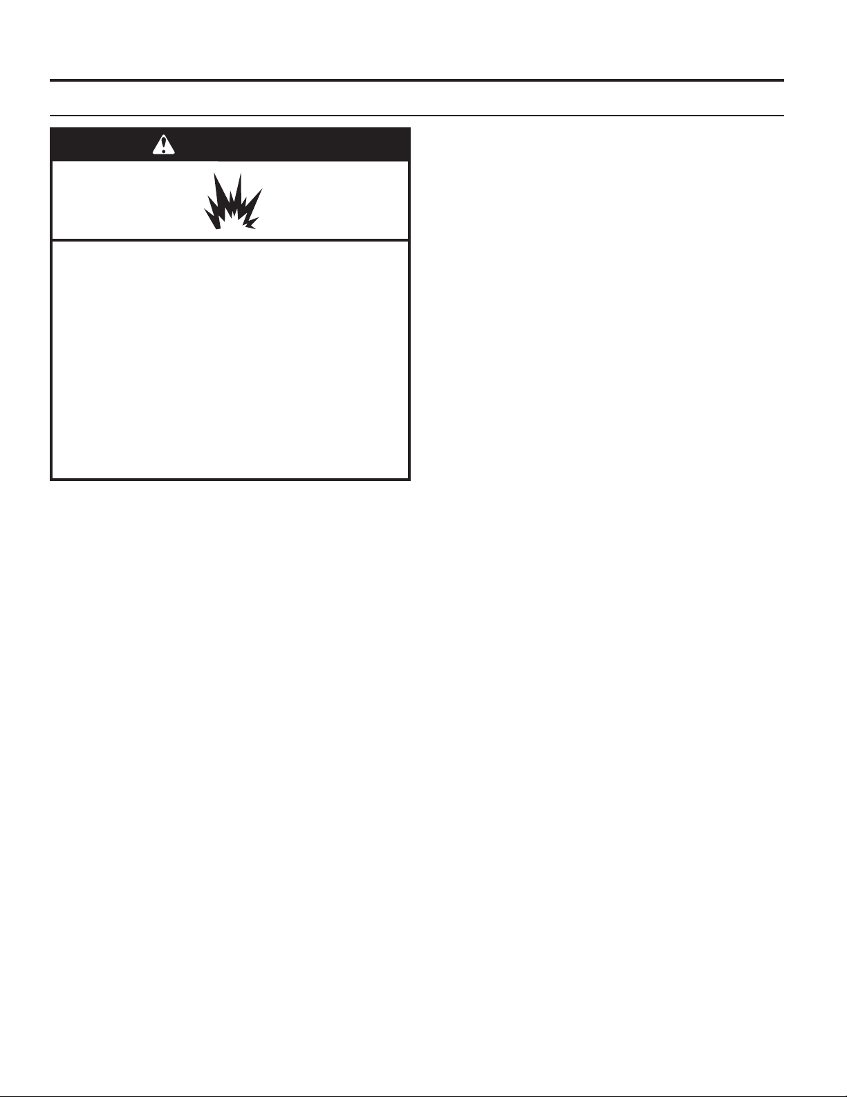
WARNING
Explosion Hazard
Use a new CSA International approved gas supply line.
Install a shut-off valve.
Securely tighten all gas connections.
If connected to propane, have a qualified person make
sure gas pressure does not exceed 13" (330 mm) water
column.
Examples of a qualified person include:
licensed heating personnel,
authorized gas company personnel, and
authorized service personnel.
Failure to do so can result in death, explosion, or fire.
When installed above 10,000 feet (3048 m), a four percent
(4%) reduction of the burner B.T.U. rating shown on the model/
serial plate is required for each 1,000 foot (305 m) increase in
elevation. For assistance when converting to other gas types
and/or installing above 10,000 feet (3048 m) elevation, contact
your local service company.
Gas supply pressure required to operate this dryer is
a minimum of 5.2" wc (1.30 kPa) and a maximum of
10.5" wc (2.62 kPa).
IMPORTANT: Observe all governing codes and ordinances.
This installation must conform with all local codes and
ordinances. In the absence of local codes, installation must
conform with American National Standard, National Fuel Gas
Code ANSI Z223.1/NFPA 54 or CAN/CSA B149.
A copy of the above code standards can be obtained from:
National Fire Protection Association
One Batterymarch Park, Quincy, MA 02269
CSA International
8501 East Pleasant Valley Road
Cleveland, Ohio 44131-5575
The design of this dryer has been certied by CSA International
for use at altitudes up to 10,000 feet (3048 m) above sea level
at the B.T.U. rating indicated on the model/serial plate. Burner
input adjustments are not required when the dryer is operated
up to this elevation.
12
Page 13
Type of Gas
This dryer is equipped for use with natural gas. It is designcertied by CSA International for propane and butane gases
with appropriate conversion. No attempt shall be made to
convert dryer from gas specied on serial/rating plate for use
with a different gas without consulting the serving gas supplier.
Conversion must be done by a qualied service technician.
Gas conversion kit part number is W10402145. This number
can also be found on a label on the gas valve burner base.
Gas Supply Line
INSTALLATION REQUIREMENTS
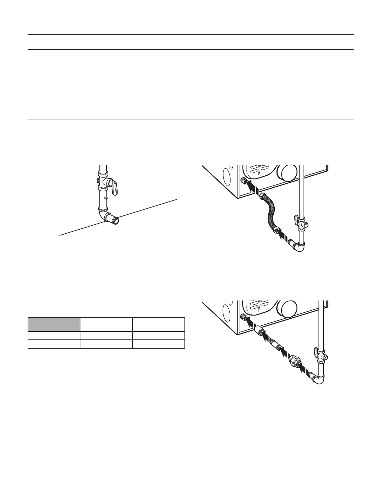
Recommended Method
Provide a gas supply line of 1⁄2" (13 mm) rigid (IPS) pipe
to dryer location. Pipe joint compounds that resist action
of propane gas must be used. Do not use TEFLON®† tape.
With propane gas, piping or tubing size can be 1⁄2" (13 mm)
minimum. Usually, propane gas suppliers determine size and
materials used in the system.
Gas Supply Pressure Testing
A 1/8" NPT minimum plugged tapping, accessible for gauge
testing, must be installed immediately downstream of the
installed shut-off valve to the dryer (as shown above). The
dryer must be disconnected from the gas supply piping system
during any pressure testing of the system at test pressures in
excess of 1/2" psig (352 kg/m2). The dryer must be isolated
from the gas supply piping system by closing the equipment
shut-off valve during any pressure testing of the gas supply
piping system at test pressures equal to or less than 1/2" psig
(352 kg/m2).
Expected Pressures For Gas Supply
Minimum
Inches of Water
Natural Gas 5.2 10.5
Propane Gas 8.0 13.0
Alternate Method
The gas supply may also be connected using 3⁄8" (10 mm)
approved copper or aluminum tubing. If the total length of
the supply line is more than 20 ft. (6.1 m), larger tubing will
be required.
If using natural gas, do not use copper tubing. Pipe joint
compounds that resist action of type of gas supplied must
be used.
Shut-off valve required
The supply line must be equipped with a manual shut-off
valve installed within 6 ft. (1.8 m) of dryer in accordance
with National Fuel Gas Code, ANSI Z223.1. This valve should
be located in same room as dryer. It should be in a location
that allows ease of opening and closing. Do not block access
to shut-off valve. In Canada, an individual manual shut-off
valve must be installed in accordance with the B149 installation
codes CAN/CGA B149.1 and CAN/CGA B149.2.
Maximum
Inches of Water
Flexible Metal Appliance Connector
It is recommended that a new exible stainless steel gas line,
design-certied by CSA International, be used for connecting
the dryer to the gas supply line. (The gas pipe which extends
through the lower rear of the dryer is provided with 3⁄8"
male pipe thread.)
NOTE: Do not kink or damage the exible stainless steel gas
line when moving the dryer.
Rigid Pipe Connection
The rigid pipe connection requires a combination of pipe ttings
to obtain an in-line connection to the dryer.
†®TEFLON is a registered trademark of Chemours.
13
Page 14
(155 cm
)
INSTALLATION REQUIREMENTS
Electric Dryer Installation Requirements
Location Requirements
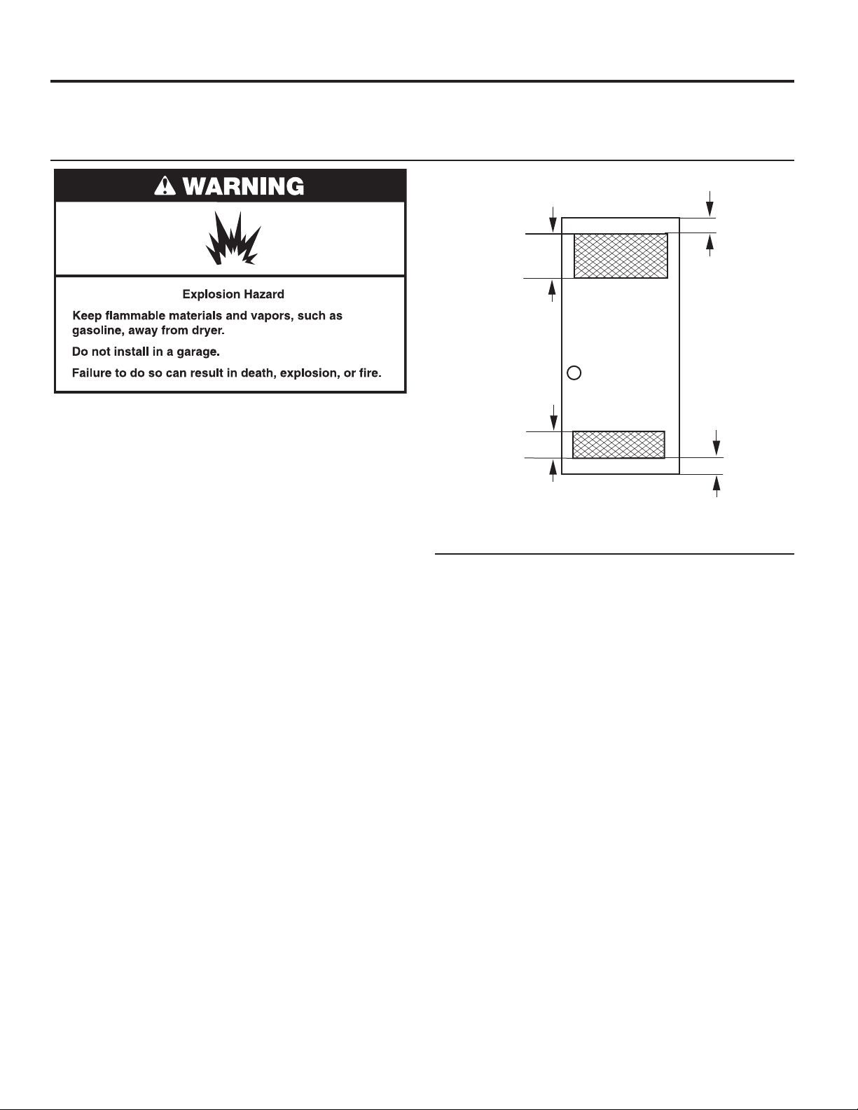
The dryer must be exhausted outdoors.
2
48 in.
(310 cm2)
3"
(76 mm)
Your dryer can be installed in a basement, laundry room,
or recessed area.
This dryer is not intended for installation in a mobile home.
Companion appliance location requirements should also be
considered.
IMPORTANT: Do not install or store the dryer where it will be
exposed to water and/or the weather. Proper installation is your
responsibility.
You will need:
■ A grounded electrical outlet located within 6 ft. (1.8 m) of
where the power cord is attached to the back of the dryer.
See “Electrical Requirements.”
■ A level oor with a maximum slope of 1" (25 mm) under
entire dryer. Installing the dryer on soft oor surfaces,
such as carpets or surfaces with foam backing, is not
recommended.
Electric dryer installation clearances
■ The location must be large enough to allow the dryer door
to be fully opened.
■ Additional spacing should be considered for ease of
installation and servicing. The door opens more than 180°.
■ Additional clearances might be required for wall, door,
and oor moldings.
■ Additional spacing of 1" (25 mm) on all sides of the dryer
is recommended to reduce noise transfer.
Recessed Area and Closet Installation Instructions
This dryer may be installed in a recessed area or closet. For
recessed area and closet installations, minimum clearances
can be found on the warning label on the rear of the dryer
or in “Dimensions/Clearances.”
The installation spacing is in inches and is the minimum
allowable. Additional spacing should be considered for ease
of installation, servicing, and compliance with local codes
and ordinances.
If closet door is installed, the minimum unobstructed air
opening in the top and bottom is required. Louvered doors
with equivalent air openings are acceptable.
Front
Front
View
View
24 in.
2
2
)
Closet
Closet
Door
door
3"
(76 mm
Electrical Requirements – U.S.A. only
It is your responsibility:
■ To contact a qualied electrical installer.
■ To be sure that the electrical connection is adequate and in
conformance with the National Electrical Code, ANSI/NFPA
70-latest edition and all local codes and ordinances.
■ The National Electrical Code requires a 4-wire power supply
connection for homes built after 1996, dryer circuits involved
in remodeling after 1996, and all mobile home installations.
■ A copy of the above code standards can be obtained from:
National Fire Protection Association, One Batterymarch
Park, Quincy, MA 02269.
■ To supply the required 3- or 4-wire, single-phase, 120/240
volt, 60 Hz., AC-only electrical supply (or 3- or 4-wire,
120/208 volt electrical supply, if specied on the serial/
rating plate) on a separate 30-amp circuit, fused on both
sides of the line. A time delay fuse or circuit breaker is
recommended. Connect to an individual branch circuit.
Do not have a fuse in the neutral or grounding circuit.
■ Do not use an extension cord.
■ If codes permit and a separate ground wire is used, it is
recommended that a qualied electrician determine that
the ground path is adequate.
14
Page 15
Electrical Requirements – U.S.A. only (cont.)
INSTALLATION REQUIREMENTS
Electrical Connection
To properly install your dryer, you must determine the type
of electrical connection you will be using and follow the
instructions provided for it here.
■ This dryer is manufactured ready to install with a 3-wire
electrical supply connection. The neutral ground conductor
is permanently connected to the neutral conductor (white
wire) within the dryer. If the dryer is installed with a 4-wire
electrical supply connection, the neutral ground conductor
must be removed from the external ground connector
(green screw), and secured under the neutral terminal
(center or white wire) of the terminal block. When the neutral
ground conductor is secured under the neutral terminal
(center or white wire) of the terminal block, the dryer cabinet
is isolated from the neutral conductor.
■ If local codes do not permit the connection of a neutral
ground wire to the neutral wire, see “Optional 3-wire
connection” section.
■ A 4-wire power supply connection must be used when the
appliance is installed in a location where grounding through
the neutral conductor is prohibited. Grounding through the
neutral is prohibited for (1) new branch-circuit installations
and (2) areas where local codes prohibit grounding through
the neutral conductor.
Electric Dryer Grounding
Electric Dryer Power Supply Cord
If using a power supply cord:
Use a UL-listed power supply cord kit marked for use with
clothes dryers. The kit should contain:
■ A UL-listed 30-amp power supply cord, rated 120/240 volt
minimum. The cord should be type SRD or SRDT and be at
least 4 ft. (1.22 m) long. The wires that connect to the dryer
must end in ring terminals or “U”-shaped spade terminals
with upturned ends.
■ A UL-listed strain relief.
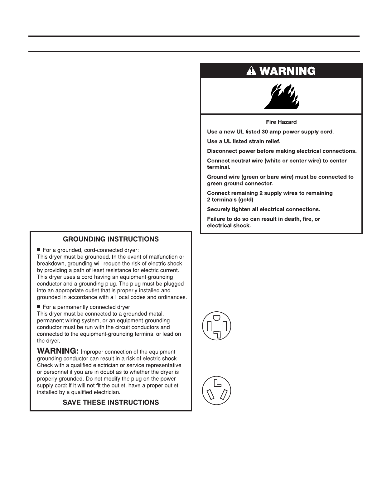
If your outlet looks like this:
Then choose a 4-wire power supply cord with ring
or spade terminals and UL-listed strain relief. The
4-wire power supply cord, at least 4 ft. (1.22 m)
long, must have four 10-gauge copper wires and
match a 4-wire receptacle of NEMA Type 14-30R.
4-wire
receptacle
(14-30R)
If your outlet looks like this:
3-wire
receptacle
(10-30R)
The ground wire (ground conductor) may be either
green or bare. The neutral conductor must be
identied by a white cover.
Then choose a 3-wire power supply cord with ring
or spade terminals and UL-listed strain relief. The
3-wire power supply cord, at least 4 ft. (1.22 m)
long, must have three 10-gauge copper wires and
match a 3-wire receptacle of NEMA Type 10-30R.
15
Page 16
INSTALLATION REQUIREMENTS
Direct Wire
If connecting by direct wire:
Power supply cable must match power supply (4-wire or 3-wire)
and be:
■ Flexible armored cable or nonmetallic sheathed copper
cable (with ground wire), covered with exible metallic
conduit. All current-carrying wires must be insulated.
■ 10-gauge solid copper wire (do not use aluminum).
■ At least 5 ft. (1.52 m) long.
Electrical Requirements – Canada only
It is your responsibility:
■ To contact a qualied electrical installer.
■ To be sure that the electrical connection is adequate
and in conformance with the Canadian Electrical Code,
C22.1 – latest edition and all local codes. A copy of the
above codes standard may be obtained from: Canadian
Standards Association, 178 Rexdale Blvd., Toronto, ON
M9W 1R3 CANADA.
■ To supply the required 4 wire, single phase, 120/240 volt,
60 Hz., AC-only electrical supply on a separate 30-amp
circuit, fused on both sides of the line. A time-delay fuse
or circuit breaker is recommended. Connect to an individual
branch circuit.
■ This dryer is equipped with a CSA International
Certied Power Cord intended to be plugged into
a standard 14-30R wall receptacle. The cord is
5 ft (1.52 m) in length. Be sure wall receptacle is
within reach of dryer’s nal location.
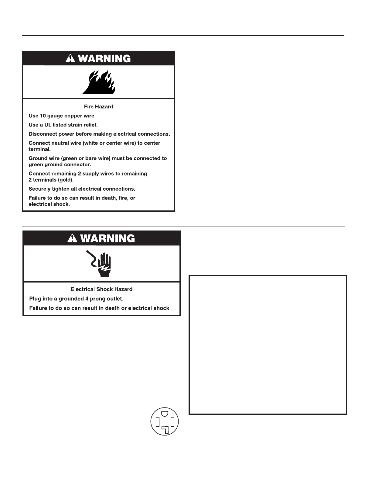
4-wire
receptacle
(14-30R)
■ Do not use an extension cord.
If you are using a replacement power supply cord,
it is recommended that you use Power Supply Cord
Replacement Part Number 8579325. For further information,
please reference the service numbers located in the
“Assistance or Service” section.
GROUNDING INSTRUCTIONS
■
For a grounded, cord-connected dryer:
This dryer must be grounded. In the event of malfunction or
breakdown, grounding will reduce the risk of electric shock
by providing a path of least resistance for electric current.
This dryer is equipped with a cord having an equipmentgrounding conductor and a grounding plug. The plug must
be plugged into an appropriate outlet that is properly
installed and grounded in accordance with all local codes
and ordinances.
WARNING: Improper connection of the equipment-
grounding conductor can result in a risk of electric shock.
Check with a qualied electrician or service representative
or personnel if you are in doubt as to whether the dryer is
properly grounded. Do not modify the plug provided with
the dryer: if it will not t the outlet, have a proper outlet
installed by a qualied electrician.
SAVE THESE INSTRUCTIONS
16
Page 17
INSTALLING LEVELING LEGS, COIN SLIDE, AND COIN BOX
The coin slide mechanism, control panel lock and key, and
coin box lock and key are not included and are available from
usual industry sources. A special coin slide extension must be
used on this model and can be purchased from the coin slide
distributor.
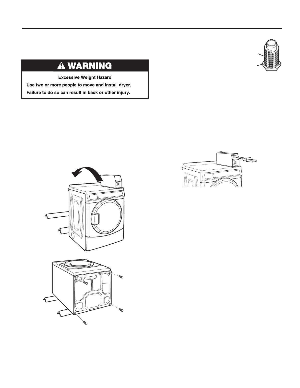
1. Prepare dryer for leveling legs
NOTE: Slide dryer onto cardboard or hardboard before moving
to avoid damaging oor covering.
Using two or more people, move dryer to desired installation
location.
Take tape off front corners of dryer. Open dryer and remove
the literature and parts packages. Wipe drum interior with damp
cloth to remove any dust.
Take two cardboard corners from the dryer carton and place
them on the oor in back of the dryer. Firmly grasp body of
the dryer and gently lay it on its back on the cardboard corners.
2. Screw in leveling legs
Examine leveling legs and nd diamond
marking. Screw legs into leg holes by
hand. Use an adjustable wrench or 1"
(25 mm) hex-head socket wrench to
nish turning legs until diamond marking
is no longer visible. Then t a covered foot
boot over each leg foot. For oors with
greater slopes, a longer leveling foot
(part no. 279810) is available.
To protect the oor, use a large piece of cardboard from the
dryer carton. Stand dryer up on the cardboard. Slide the dryer
until it is close to its nal location. Leave enough room for
electrical connection and to connect the exhaust vent.
On some models: The meter case houses the factory-installed
coin slide mechanism, service lock and key, and coin box lock
and key.
3. Install coin slide and coin box
Remove the service door of the meter case by lifting
it up at the back. Install the money-accepting device.
(Refer to manufacturer’s instructions for proper installation.)
Diamond
Marking
Foot
Replace the meter case service door. Put the coin vault with
lock and key in the meter case opening.
Remove cardboard or hardboard from under dryer. Adjust
the legs of the dryer up or down until the dryer is level.
17
Page 18
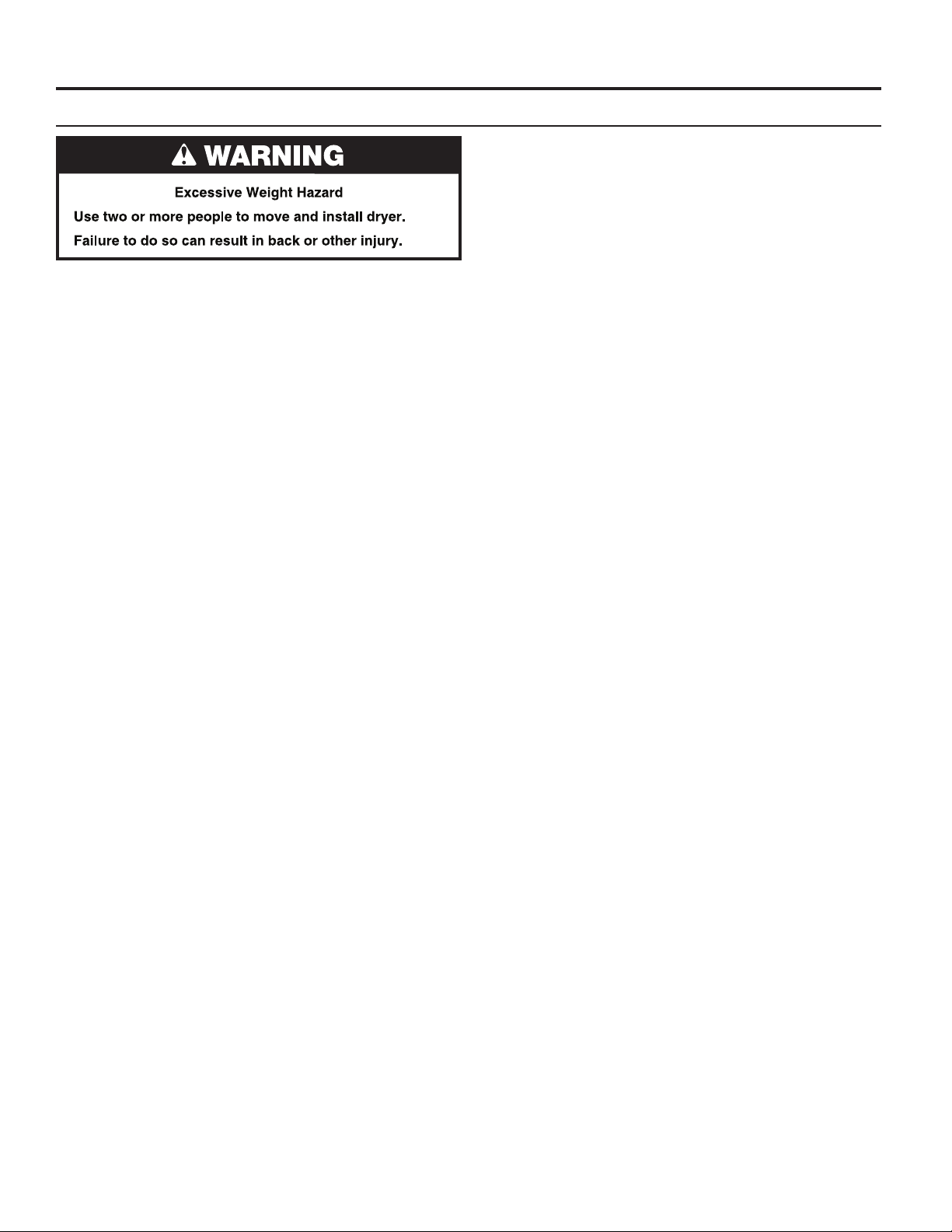
INSTALLATION INSTRUCTIONS – GAS DRYER
Make Gas Connection
1. Remove red cap from gas pipe on back of dryer.
2. Connect gas supply to dryer. Use a pipe thread compound
approved for the type of gas supplied. If exible metal
tubing is used, be certain there are no kinks.
If necessary for service, open the front lower service panel
by using a 1/4" nutdriver to remove the 2 hex-head screws
from the bottom of the panel. Then lift up on the panel while
pulling the bottom of the panel away from the dryer.
3. Open the shut-off valve in the gas supply line and make sure
the dryer has its own gas supply opened.
4. Test all connections by brushing on an approved
noncorrosive leak-detection solution. Bubbles will show
a leak. Correct any leaks found.
18
Page 19
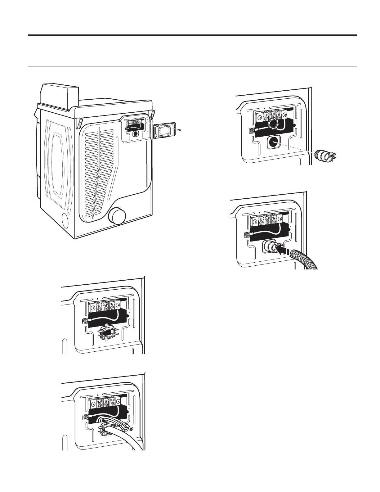
INSTALLATION INSTRUCTIONS – ELECTRIC DRYER
Electric Dryer Electrical Connections
Strain Relief
Remove Terminal Block Cover
Direct Wire Strain Relief
1. Insert strain relief.
2. Insert conduit into strain relief and tighten clamp.
Power Supply Cord Strain Relief
1. Insert strain relief.
2. Insert power cord into strain relief.
19
Page 20
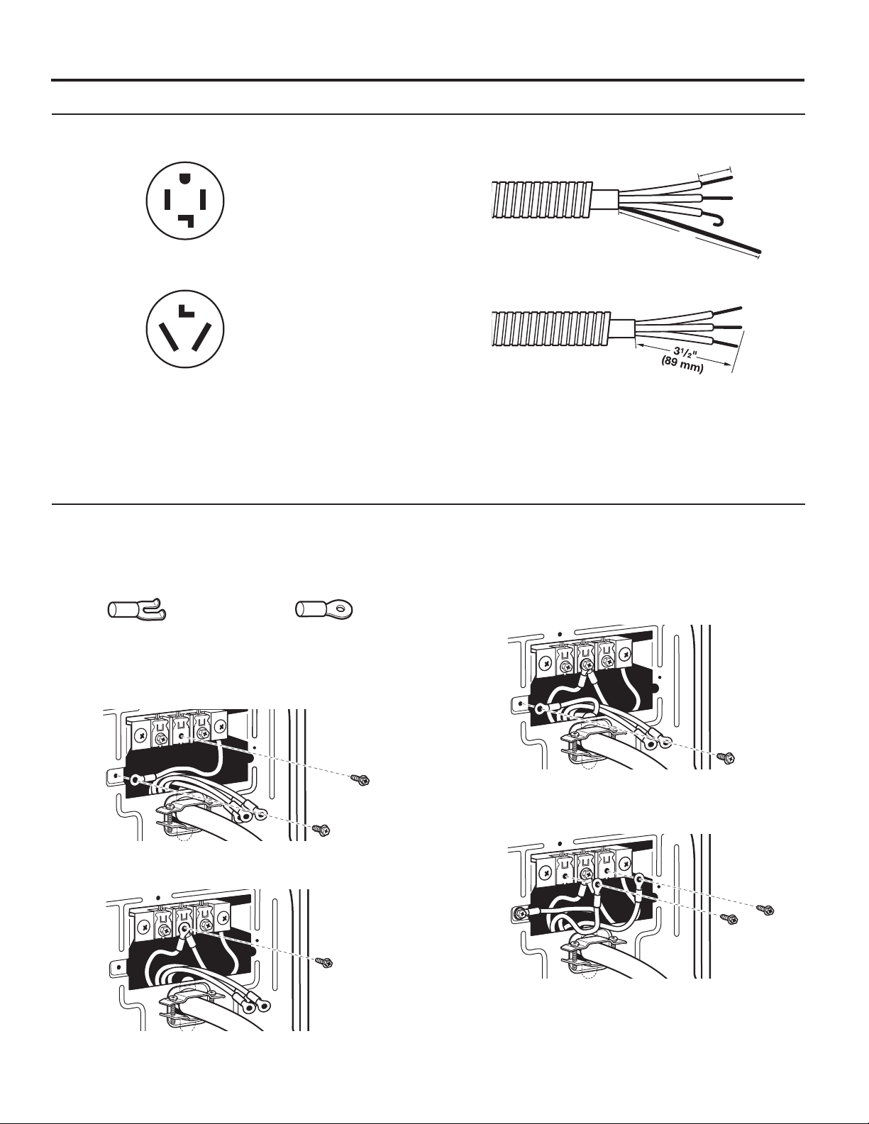
INSTALLATION INSTRUCTIONS – ELECTRIC DRYER
Connection Options
Power Cord
4-wire receptacle (NEMA Type 14-30R)
3-wire receptacle (NEMA Type 10-30R)
Connecting 4-Wire Connection: Power Supply Cord
IMPORTANT: A 4-wire connection is required for mobile
homes and where local codes do not permit the use of 3-wire
connections.
Direct Wire
4-wire direct
1"
(25 mm)
5"
(127 mm)
3-wire direct
Standard Power Supply Cord Connectors
Flanged Spade Connector Ring Connector
Connecting Ground and Neutral Wires
1. Remove center terminal block screw and the ground wire
by removing the external ground connector screw.
2. Connect ground and neutral wire to center terminal block.
Connecting Power Cord Ground Wire
3. Connect ground wire (green or bare) with external ground
connector screw.
Connecting Remaining Wires
4. Connect remaining wires with outer terminal block screws.
20
Page 21
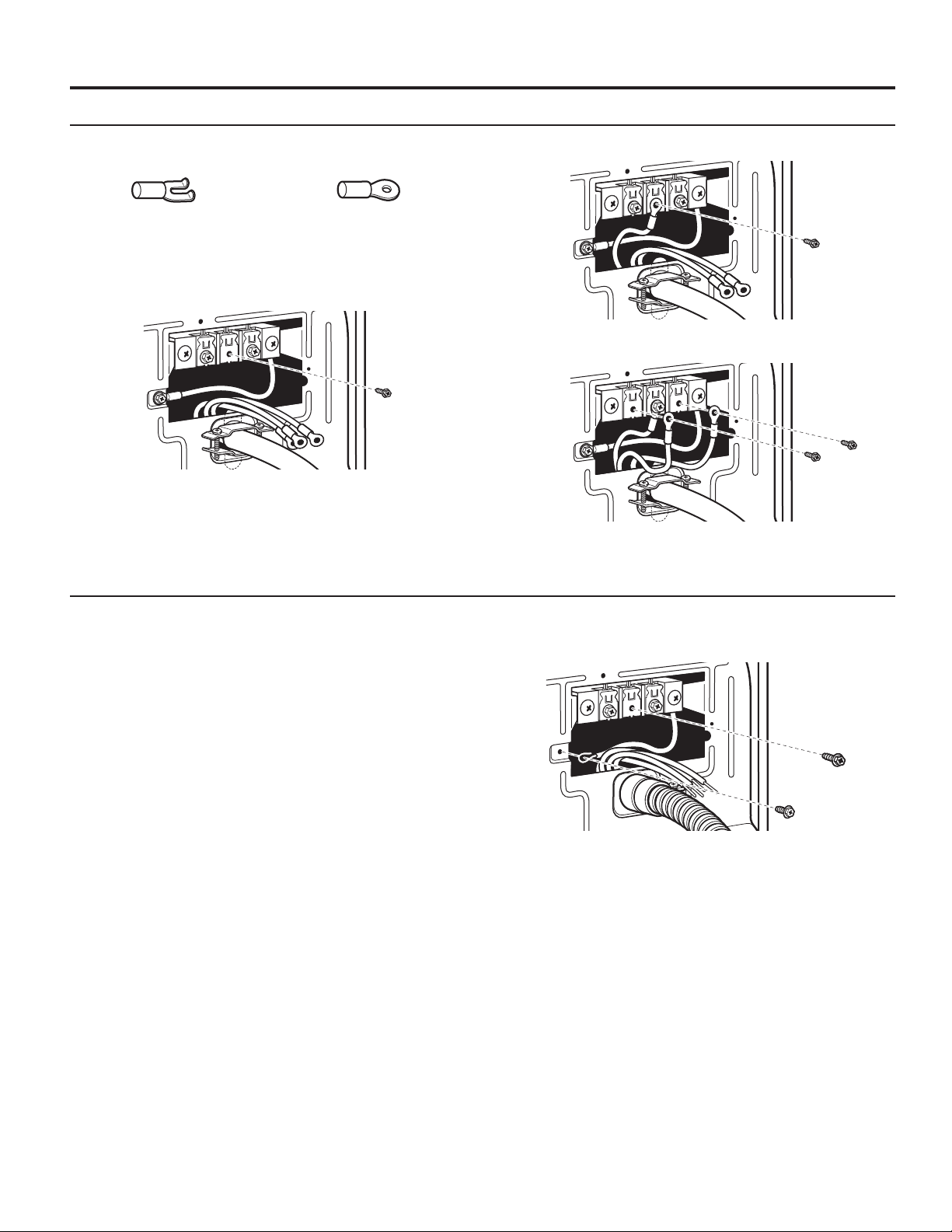
INSTALLATION INSTRUCTIONS – ELECTRIC DRYER
Connecting 3-Wire Connection: Power Supply Cord
Standard Power Cord Connectors
Flanged Spade Connector Ring Connector
Connecting Neutral Wire
1. Loosen or remove center terminal block screw.
Connecting 4-Wire Connection: Direct Wire
2. Connect neutral wire to center terminal block.
3. Connect remaining wires with outer terminal block screws.
IMPORTANT: A 4-wire connection is required for mobile
homes and where local codes do not permit the use of 3-wire
connections.
Direct wire cable must have 5 ft. (1.52 m) of extra length
so dryer can be moved if needed.
Strip 5" (127 mm) of outer covering from end of cable,
leaving bare ground wire at 5" (127 mm). Cut 11⁄2" (38 mm)
from 3 remaining wires. Strip insulation back 1" (25 mm).
Shape ends of wires into a hook shape.
Connecting Ground and Neutral Wires
1. Remove center terminal block screw and the ground wire
by removing the external ground connector screw.
21
Page 22
INSTALLATION INSTRUCTIONS – ELECTRIC DRYER
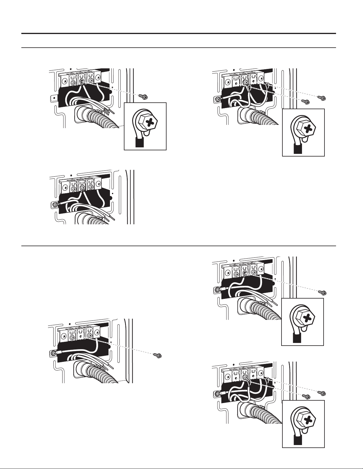
Connecting 4-Wire Connection: Direct Wire (cont.)
Connecting Ground and Neutral Wires (cont.)
2. Connect ground and neutral wire to center terminal block.
Connecting Direct Wire Ground
3. Connect ground wire (green or bare) with external ground
connector screw.
Connecting Remaining Wires
4. Connect remaining wires to outer terminal block.
Connecting 3-Wire Connection: Direct Wire
Use where local codes permit connecting
cabinet-ground conductor to neutral wire.
Direct wire cable must have 5 ft. (1.52 m) of extra length so
dryer can be moved if needed.
Strip 31⁄2" (89 mm) of outer covering from end of cable. Strip
insulation back 1" (25 mm). If using 3-wire cable with ground
wire, cut bare wire even with outer covering. Shape ends
of wires into a hook shape.
Connecting Neutral Wire
1. Loosen or remove center terminal block screw.
2. Connect neutral wire to center terminal block.
3. Connect remaining wires to outer terminal block.
22
Page 23
INSTALLATION INSTRUCTIONS – ELECTRIC DRYER
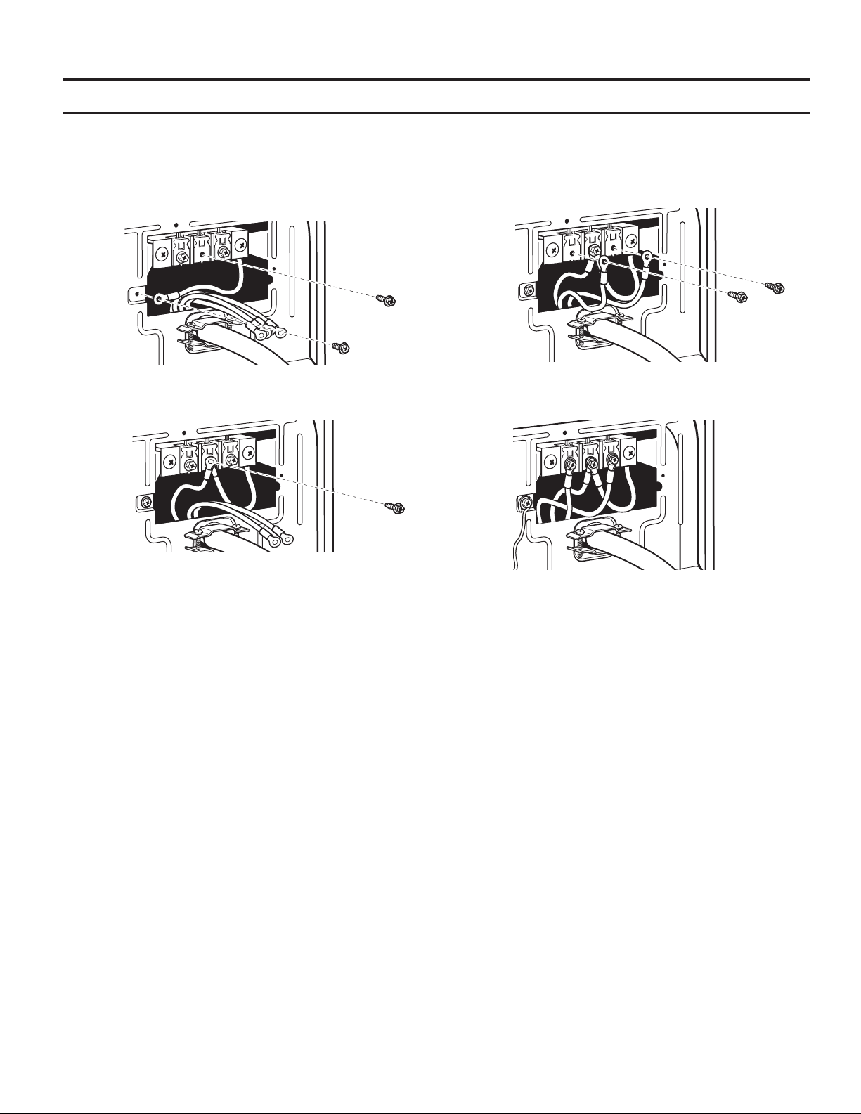
Connecting 3-Wire Connection: Optional
Use for direct wire or power supply cord where local codes
do not permit connecting cabinet-ground conductor to
neutral wire.
Connecting Neutral Wire
1. Remove center terminal block screw. Also remove neutral
ground wire by removing external ground conductor screw.
3. Connect remaining wires to outer terminal block.
2. Connect neutral wire and neutral wire of power supply cord/
cable to center terminal block.
4. Connect a separate copper ground wire from the external
ground conductor to an adequate ground.
23
Page 24
LEVELING
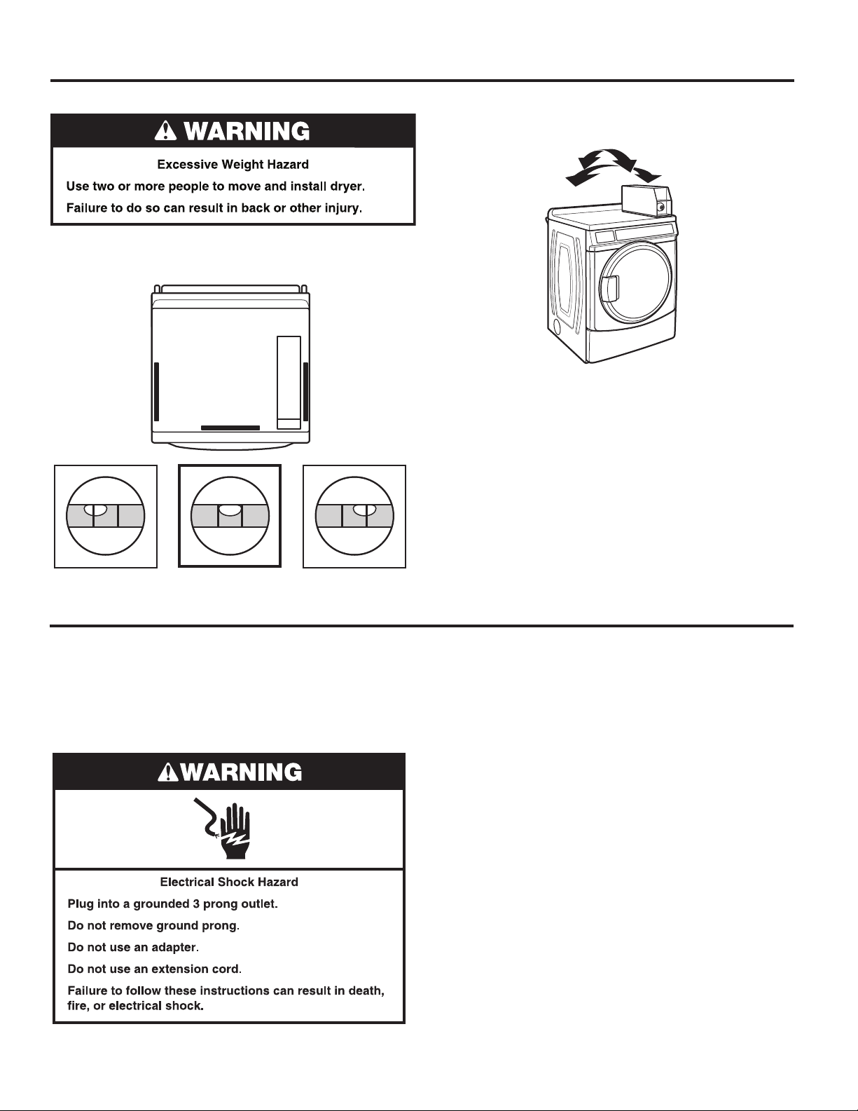
Leveling your dryer properly reduces excess noise and vibration. 2. Grip dryer from top and rock back and forth, making sure all
four feet are rmly on oor. Repeat, rocking dryer from side
to side. If dryer rocks, adjust leveling feet.
1. Remove cardboard from beneath dryer. Place a level on top
edges of dryer, checking each side and front. If not level, tip
dryer and adjust feet up or down, repeating as necessary.
3. If dryer is not level, turn the leveling feet counterclockwise
to lower the dryer or clockwise to raise the dryer. Recheck
levelness of dryer and that all four feet are rmly in contact
with the oor. Repeat as needed.
HELPFUL TIP: You may want to prop up front of dryer about 4"
(102 mm) with a wood block or similar object that will support
weight of dryer.
Not Level LEVEL Not Level
COMPLETE INSTALLATION
1. Check the electrical requirements. Be sure that you have the
correct electrical supply and the recommended grounding
method. See “Electrical Requirements.”
2. Check that all parts are now installed. If there is an extra part,
go back through the steps.
3. Check that you have all of your tools.
4. Dispose of/recycle all packaging materials.
6. Check dryer operation. Close dryer door. Insert coins in slide
and press slide in slowly. Select the Whites and Colors cycle
and let the dryer run for at least ve minutes.
NOTE: Dryer door must be closed for dryer to operate.
7. Open the dryer door. Check that the inside of the dryer is
warm. If the burner does not ignite and you can feel no heat
inside the dryer, shut off dryer for ve minutes. Check that
all supply valve controls are in “ON” position and that the
electrical cord is plugged in. Repeat ve-minute test.
8. If drying time is too long, make sure that the lint screen
is clean and that there are no obstructions to airow
in the dryer vent system.
9. Restart the dryer and allow it to complete a full cycle to make
sure it is working properly.
5. Plug into a grounded outlet, or connect power.
24
Page 25
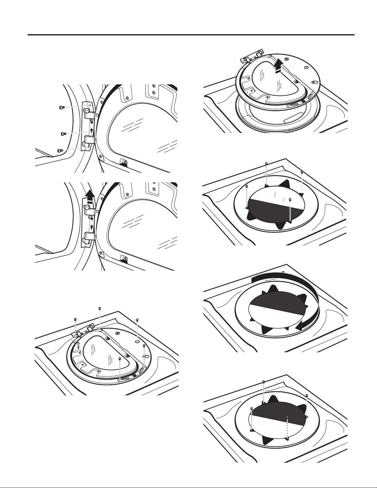
REVERSING DRYER DOOR SWING (OPTIONAL)
Remove the Door Assembly
1.
Place a towel or soft cloth on top of dryer or work space
to avoid scratching of the surface.
2.
Remove 3 of the 4 screws that hold the door hinge on the
front panel of the dryer. Partially loosen the remaining screw
with keyhole opening and lift the door off the screw.
4. Lift the inner door assembly off outer door assembly.
5. Remove 4 Phillips-head screws to release center insert from
outer door ring.
3.
Lay the door assembly on a previously prepared at surface
with the inside (inner door assembly) facing up, and remove
6 phillips-head screws to release outer door assembly from
inner door assembly.
NOTE: It is important that you remove only the 6 indicated
screws.
6. Lift and rotate center insert 180 degrees.
7. Reassemble the center insert and outer door ring with the
4 screws
25
Page 26
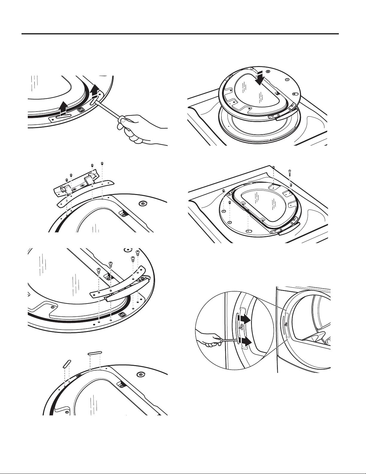
REVERSING DRYER DOOR SWING (OPTIONAL)
Reverse Hinge
1.
Use a small at-blade screwdriver to remove 2 plug strips
from the inner door. Slide the head of the screwdriver under
the plugs, without scratching inner door surface, and lift
up strip.
2.
Remove the 4 screws that attach to inner door hinge.
Replace the Door Assembly
1. Place the inner door assembly inside the outer door
assembly.
2.
Reassemble the inner and outer door assemblies with
the 6 screws.
3. Move hinge to other side. Reinstall 4 screws.
4. Reinstall plug strips on opposite side of the inner door.
Reverse the strike
1.
Use a small at-blade screwdriver to remove plug strip from
the dryer door opening. Slide the head of the screwdriver
under the plugs, without scratching dryer surface, and lift
up strip.
5. Check for ngerprints on the glass. Clean if necessary.
26
Page 27
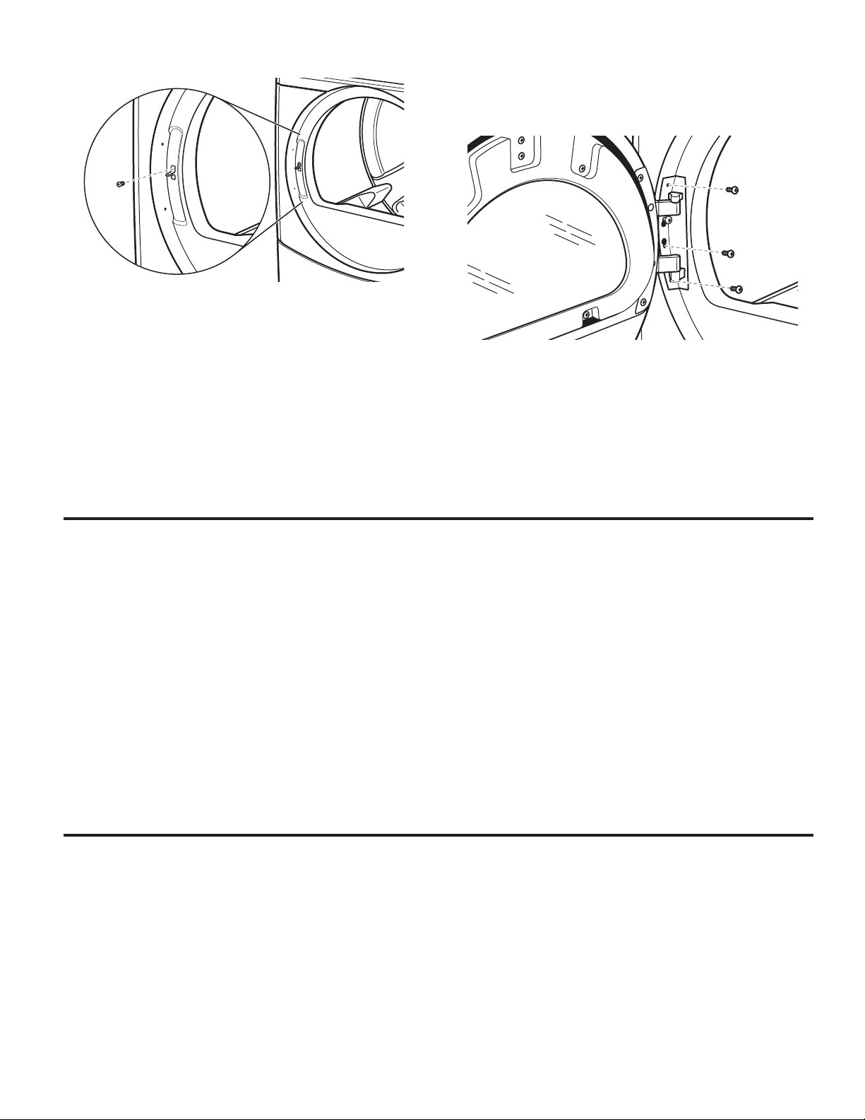
2. Remove the strike using a Phillips screwdriver.
3. Insert strike on the opposite side.
Reinstall the door
1. Partially insert the third screw from the top; then slide the
hinge onto this screw while hooking the hinge into the front
panel hole. Reattach door to dryer front panel with the
remaining three screws.
2. Check for ngerprints on the glass. Clean if necessary.
3. Close door and check that it latches securely.
MAINTENANCE INSTRUCTIONS
■ Clean lint screen before and after each cycle.
■ Removing accumulated lint:
From inside the dryer cabinet:
Lint should be removed every 2 years or more often,
depending on dryer usage. Cleaning should be done
by a qualied person.
From the exhaust vent:
Lint should be removed every 2 years, or more often,
depending on dryer usage.
■ Keep area around dryer clear and free from combustible
materials, gasoline, and other ammable vapors and liquids.
■ Keep dryer area clear and free of items that would obstruct
the ow of combustion and ventilation air.
If dryer does not operate, check the following:
■ Electrical supply is connected.
■ Circuit breaker is not tripped or house fuse is not blown.
■ Door is closed. Listen closely to hear the door switch
activate.
■ Control is set up properly and display shows cycle time.
■ Cycle selection button has been pushed rmly.
■ For gas dryers, check that gas supply shut-off valves are set
in open position.
IF YOU NEED ASSISTANCE
If you need service, all warranty service is provided exclusively by our authorized Whirlpool Service Providers. In the U.S. and
Canada, direct all requests for warranty service to: Whirlpool Customer Experience Center.
In the U.S.A. call 1-800-253-1301. In Canada call 1-800-807-6777.
If outside the 50 United States and Canada, contact your authorized Whirlpool dealer to determine if another warranty applies.
27
Page 28
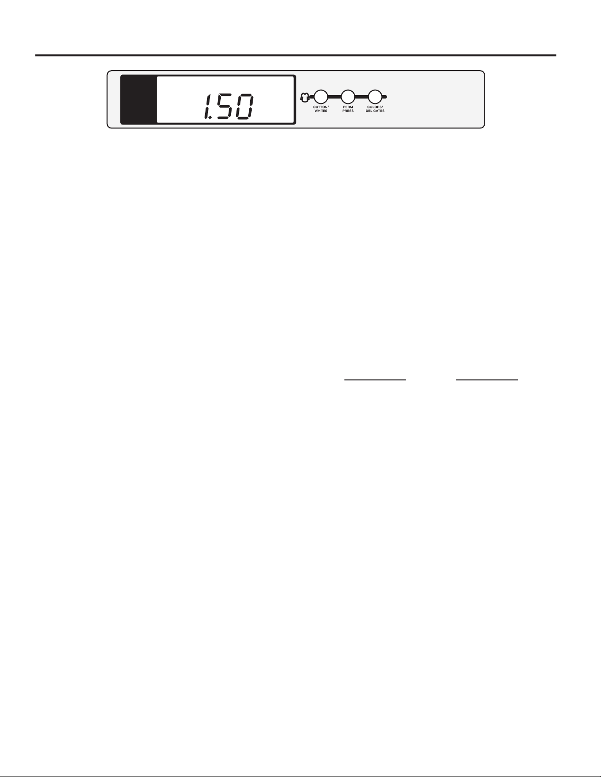
ELECTRONIC CONTROL SETUP INSTRUCTIONS
PRICE
NOTE: After the dryer has been installed and plugged in,
the display will show “0 MINUTES.” After the door has been
opened and closed, the display will show the vend price.
General User Information
SCROLLING “OUT OF ORDER” MESSAGE, FOLLOWED BY
A FAILURE OR DIAGNOSTIC CODE, SHOWING IN DISPLAY –
This condition indicates the dryer is inoperative.
“0 MINUTES” SHOWING IN DISPLAY – This indicates the
dryer cannot be operated. Coins dropped or debit inputs during
this condition will be stored in escrow but cannot be used until
normal operation is restored by opening and closing the door.
If a door switch has failed, causing “0 MINUTES” to remain
in the display after the door is opened and closed, it must be
replaced before normal operation can be restored.
COLD START (Initial rst use) – Dryer is programmed at the
factory as follows: $1.50 dry price (30 minutes).
9160 model only: $0 dry price (45 minutes)
WARM START (after power failure) – A few seconds after
power is restored, if a cycle was in progress at the time of the
power failure, “RESELECT CYCLE” will ash in the display,
indicating the need for a fabric setting button to be pressed
to restart dryer.
PRICING – After the door is opened and then closed
following the completion of a cycle, the display indicates the
cycle price (unless set for free operation, where the display will
ash “SELECT CYCLE”). As coins are dropped or debit inputs
arrive, the display will change to lead the user through the
initiation of a cycle.
There are four (4) types of dryer pricing:
Fixed “Vend” Pricing
A dryer setup for “Fixed Cycle” operation can only accept
additional time accumulated by increments equal to the length
of a complete dry cycle. A maximum of 99 minutes may be
purchased; no additional credit is given for coins dropped
with 99 minutes in the display.
Accumulator Pricing
If option d is set to d. 00, and the 6 code is set to one
coin 1, then accumulator pricing is in effect. Cycle time
can be purchased one coin at a time up to the maximum
time of 99 minutes.
Fixed Cycle With Top Off Pricing (available for use with coin
drops or card readers only)
A dryer set to offer “Top Off” capability will allow time to
be added to an existing dry cycle in increments equal to
the number of minutes of dry time per quarter (coin 1), up to
99 minutes, regardless of the cost required to start the dryer.
No credit is given for coins or debit inputs entered when the
control is displaying 99 minutes.
FREE CYCLES – This is established by setting the cycle price
to zero. When this happens, “SELECT CYCLE” will appear
rather than a cycle price. Any cycle started as a free cycle
will automatically terminate when the door is opened.
DEBIT CARD READY – This dryer is debit card ready.
It will accept a variety of debit card systems, but does NOT
come with a debit card reader. Refer to the debit card reader
manufacturer for proper dryer setup. When a Generation 2 card
reader is installed, the dryer is placed in enhanced debit mode.
In Enhanced Debit Mode, the top off price can be set
independently (see VALUE OF COIN 2), and the top off time
is calculated according to the following equation:
top off price
In models converted to a Generation 1 debit card system,
debit pulses represent the equivalent of one coin (coin 1).
NOTE: Enhanced debit mode cannot be deselected.
full cycle price
=
top off time
full cycle length
Control Set-up Procedures
IMPORTANT: Read all instructions before operating.
The fabric setting buttons along with the digital display are
used to set up the dryer controls.
The display can contain 4 numbers and/or letters and a decimal
point. These are used to indicate the set-up codes and related
code values available for use in programming the dryer.
28
Page 29
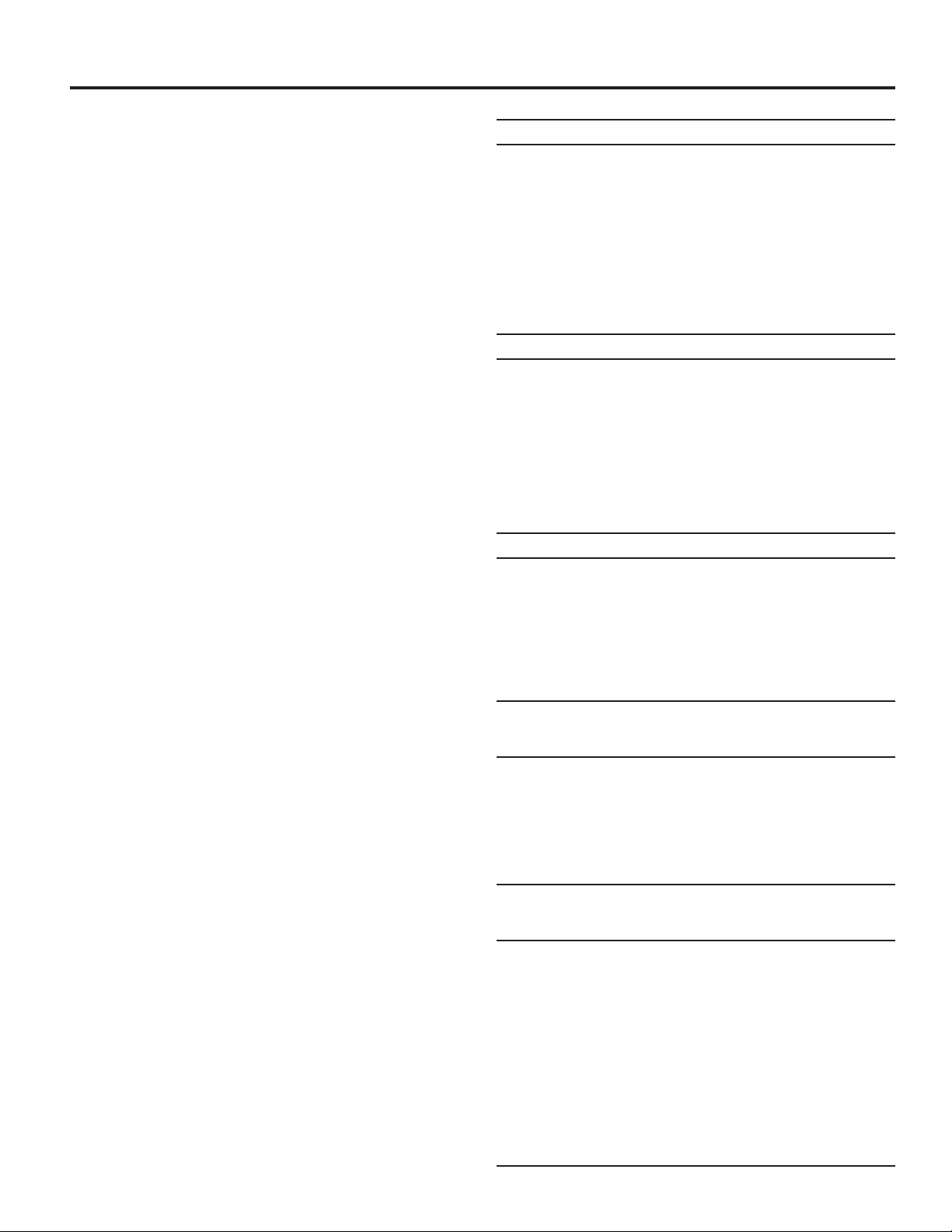
ELECTRONIC CONTROL SETUP INSTRUCTIONS
How to Use the Buttons to Program the Controls
1. The COTTON/WHITES button is used to adjust the values
associated with set-up codes. Pressing the button will
change the value by increments. Rapid adjustment is
possible by holding down the button.
2. The PERM PRESS button will advance through the set-up
codes. Pressing this button will advance to the next available
set-up code. Holding down the button will automatically
advance through the set-up codes at a rate faster than
1 per second.
3. The COLORS/DELICATES button is used to select
or deselect options.
Start Operating Setup
Insert service access door key, turn, and lift to remove service
access door.
Dryers with Card Reader Installed:
Once the debit card reader is installed (according to the
reader manufacturer’s instructions), the set-up mode can be
entered by inserting a manual set-up card (supplied by the
reader manufacturer) into the card slot. If manual set-up card
is not available, only the diagnostic mode can be entered by
removing the service access door.
IMPORTANT: To access set-up mode or diagnostic mode,
use a service key (9050 models) to open the service access
door. If a card reader is installed, a service card is available
for accessing diagnostics. If a service key is not available
(9060 models), the AA1 connector must be removed or
the Service Access Code described below must be used.
The console must not be opened unless power is rst
disconnected from the dryer. To access connector AA1:
1. Unplug dryer or disconnect power.
2. Open console, remove plug on AA1, and close console.
3. Plug in dryer or reconnect power.
The dryer is now in the set-up mode.
To enter the alternative Service Access Code and enter set-up
mode: Press the Left Button, Right Button, Left Button, Right
Button, and Right Button.
NOTE: It is not necessary to set up the dryer with the following
codes; the dryer is pre-set at the factory. These codes can be
used to change settings, if desired.
Set-Up Codes
■ The PERM PRESS button will advance from code to code.
■ The COTTON/WHITES button will change the code value.
■ The COLORS/DELICATES button will select or deselect
options.
The set-up code is indicated by the one or two left-hand
characters. The set-up code value is indicated by the two
or three right-hand characters.
NOTE: The rst line of each code indicates the factory default.
Code Explanation
6. 06 REGULAR CYCLE PRICE
6. 06 When the d.xx is set to d.00, this 6.xx value represents
the number of coins (coin 1) needed to start the dryer;
may adjust from 0–39. Change this value by pressing
the COTTON/WHITES button. 6.06 = 6 coins = $1.50.
(9160 models default to 6.00.)
6. 01 When the d.xx is set to d.CS, this 6.xx value
represents the number of push-in actuations of the
coin slide to start the dryer. 6.01 would equal one coin
slide activation.
• Press the PERM PRESS button once to advance
to next code.
7. 05 REGULAR DRY TIME
7. 05 When set to Coin Drop or Card Reader operation, the
dry time equals the Regular Dry Time value multiplied
by the Regular Cycle Price value. Example: 6.06 and
7.05 = (06 x 05 = 30 minutes).
7. 45 For coinslide or OPL operation, the value is the
amount of minutes of dry time. Factory default of 45
minutes. Pressing COTTON/WHITES adjusts the value
from 1–99 minutes.
• Press the PERM PRESS button once to advance
to next code.
8. 00 TYPE OF DRYER PRICING
8. 00 Fixed Cycle with Top Off. Only available for use with
coin drops or card readers. For detailed description,
see “General User Information.”
8. FC Fixed Cycle. For detailed description, see General
User Information. Use COLORS/DELICATES button
to make this selection.
• Press the PERM PRESS button once to advance
to next code.
9. 00 CYCLE COUNTER OPTION
This option is either NOT SELECTED “OFF”
or SELECTED “ON.”
9. 00 Not Selected “OFF.”
9. 0C Selected “ON” and not able to be deselected.
• Press the COLORS/DELICATES button
3 consecutive times to select “ON.” Once
selected “ON” it cannot be deselected.
• Press the PERM PRESS button once to advance
to next code.
1. 00 MONEY COUNTER OPTION
This option is either NOT SELECTED “OFF”
or SELECTED “ON.”
1. 00 Not Selected “OFF.”
1. 0C Selected “ON.”
• Press the COLORS/DELICATES button
3 consecutive times to select “ON” and 3
consecutive times to deselect (Not Selected “OFF”).
Counter resets by going from “OFF” to “ON.”
1. C0 Selected “ON” and not able to be deselected.
• To select “ON” and not able to be deselected,
rst select “ON;” then within 2 seconds press the
COLORS/DELICATES button twice, the COTTON/
WHITES button once, and exit set-up mode.
• Press the PERM PRESS button once to advance
to next code.
29
Page 30
ELECTRONIC CONTROL SETUP INSTRUCTIONS
Code Explanation
2. 00 SPECIAL PRICING OPTIONS
This option is either SELECTED ‘ON’ or NOT
SELECTED ‘OFF’.
2. 00 Not Selected ‘OFF’.
2. SP Selected ‘ON’. Press the COLORS/DELICATES button
once for this selection.
If SPECIAL PRICING OPTION is selected, there is
access to codes ‘3.’ thru ‘9.’
• Press the PERM PRESS button once to advance to
next code.
OPTIONS TO USE IF SPECIAL PRICING IS
SELECTED:
3. 06 SPECIAL CYCLE PRICE
3. 06 Represents the number of quarters (coin 1) needed
to start the dryer; may adjust from 0–39. (See b.xx
setup for VALUE OF COIN 1). Advance from 0–39
by pressing the COTTON/WHITES button. Factory
default of 6 quarters = $1.50.
3. 00 Model 9160: Factory default of 0 quarters.
• Press the PERM PRESS button once to advance to
next code.
4. 05 SPECIAL DRY TIME
4. 05 Model 9150: Represents the number of minutes per
quarter (coin 1).
Factory default of 5 minutes per coin.
Example: 6 quarters x 5 minutes = 30 minutes. By
pressing the COTTON/WHITES button, the value can
be adjusted from 1–99 minutes.
4. 45 Model 9160: Represents the xed cycle time in
minutes. As example: ‘4.45’ = 45 minutes.
• Press the PERM PRESS button once to advance to
next code.
5. 00 TIME-OF-DAY CLOCK, MINUTES
5. 00 This is the TIME-OF-DAY CLOCK, minute setting;
select 0–59 minutes by pressing the COTTON/WHITES
button.
• Press the PERM PRESS button once to advance to
next code.
6. 00 TIME-OF-DAY CLOCK, HOURS
NOTE: Uses military time – 24 hr. clock.
6. 00 This is the TIME-OF-DAY CLOCK, hour setting;
select 0–23 hours by pressing the COTTON/WHITES
button.
• Press the PERM PRESS button once to advance to
next code.
7. 00 SPECIAL PRICE START HOUR
NOTE: Uses military time – 24 hr. clock.
7. 00 This is the start hour; select 0–23 hours. Select START
HOUR by pressing the COTTON/WHITES button.
• Press the PERM PRESS button once to advance to
next code.
Code Explanation
8. 00 SPECIAL PRICE STOP HOUR
NOTE: Uses military time – 24 hr. clock.
8. 00 This is the stop hour; select 0–23 hours. Select STOP
HOUR by pressing the COTTON/WHITES button.
• Press the PERM PRESS button once to advance to
next code.
9. 10 SPECIAL PRICE DAY
9. 10 This represents the day of the week and whether
special pricing is selected for that day. A number
followed by ‘0’ indicates no selection for that particular
day (9.10). A number followed by an ‘S’ indicates
selected for that day (9.1S).
Day of week (1–7) can be chosen by pressing the
COTTON/WHITES button. Press the COLORS/
DELICATES button once to select special pricing
for each day chosen.
When exiting set-up code ‘9.’, the display must show
current day of week:
DISPLAY DAY OF WEEK CODE (selected)
10 Day 1 = Sunday 1S
20 Day 2 = Monday 2S
30 Day 3 = Tuesday 3S
40 Day 4 = Wednesday 4S
50 Day 5 = Thursday 5S
60 Day 6 = Friday 6S
70 Day 7 = Saturday 7S
• Press the PERM PRESS button once to advance to
next code.
A. 00 VAULT VIEWING OPTION
This option is either SELECTED ‘ON’ or NOT
SELECTED ‘OFF’.
A. 00 Not Selected ‘OFF’.
A. SC Selected ‘ON’. Press the COLORS/DELICATES button
once for this selection. When selected, the money
and/or cycle counts will be viewable (if counting is
selected) when the coin box is removed.
• Press the PERM PRESS button once to advance to
next code.
b. 05 VALUE OF COIN 1
b. 05 This represents the value of coin 1 in number
of nickels: 05 = $0.25 (default for 9150 and 9160
models).
• By pressing the COTTON/WHITES button, there is
an option of 1–199 nickels.
• Press the PERM PRESS button once to advance
to next code.
b. 30 With coin slide activation, this represents the total
vend price in nickels. Example: b.30 is equal to $1.50.
30
Page 31
ELECTRONIC CONTROL SETUP INSTRUCTIONS
Code Explanation
C. 20 VALUE OF COIN 2
C. 20 This represents the value of coin 2 in number
of nickels: 20 = $1.00.
• By pressing the COTTON/WHITES button, there is
an option of 1–199 nickels.
C. 05 When a Gen 2 card reader is used, this code represents
the value of top off in nickels. C.05 = $0.25.
• Press the PERM PRESS button once to advance
to next code.
d. 00 COIN SLIDE OPTION
This option is either Selected “ON” or Not Selected
“OFF.” Replacement of meter case will be needed for
coin slide mounting.
d. 00 Not Selected ‘OFF’.
d. CS Selected ‘ON’.
NOTE: This option needs to be set to ‘00’ unless the
meter case has been changed to accept a coin slide
device.
Press the COLORS/DELICATES button 3 consecutive
times for this selection. When coin slide mode is
selected, set ‘b.’ equal to value of vend price in
nickels. Set ‘6 XX’ (REGULAR CYCLE PRICE) and
‘3.XX’ (SPECIAL CYCLE PRICE) to number of slide
operations.
NOTE: If the installer sets up ‘CS’ on a coin drop
model, the dryer will not register coins inserted.
• Press the PERM PRESS button once to advance
to next code.
E. 00 ADD COINS OPTION
This option is either Selected ‘ON’ or Not Selected
‘OFF’. This option causes the customer display to
show the number of coins (coin 1) to enter, rather
than the dollars-and-cents amount.
E. 00 Not Selected ‘OFF’.
E. AC Selected ‘ON’.
Press the COLORS/DELICATES button 3 consecutive
times for this selection.
9160 MODELS ONLY: In enhanced debit mode, this
option is not selectable.
• Press the PERM PRESS button once to advance
to next code.
J. Cd PAYMENT MODE (COIN/DEBIT OPTION)
J. Cd Both coin and debit selected. Press the COLORS/
DELICATES button 3 consecutive times to change
this selection.
J. C_ Coins selected, debit disabled. Press the COLORS/
DELICATES button 3 consecutive times to change
this selection.
J. _d Debit Card selected, coin disabled (default for 9160
models). This selection must be used for free vend.
Press the COLORS/DELICATES button 3 consecutive
times to change this selection.
J. Ed Enhanced Debit is self-selected when a Generation
2 card reader is installed in the dryer. The “Ed” option
cannot be manually selected or deselected.
• Press the PERM PRESS button once to advance
to next code.
Code Explanation
L. 00 PRICE SUPPRESSION OPTION
This option is either Selected ‘ON’ or Not Selected
‘OFF’. This option causes the customer display to
show ‘AVAILABLE’ or ‘ADD’ rather than the amount
of money to add. (Used mainly in debit installations.)
L. 00 Not Selected ‘OFF’.
L. PS Selected ‘ON’. Press the COLORS/DELICATES button
once for this selection.
• Press the PERM PRESS button once to advance
to next code.
n. CE CLEAR ESCROW OPTION
This option is either Selected “ON” or Not Selected
“OFF.” When selected, money held in escrow for 30
minutes without further escrow or cycle activity will
be cleared.
n. 00 Not Selected “OFF.”
n. CE Selected “ON.”
• Press the COLORS/DELICATES button once
to change this selection.
• Press the PERM PRESS button once to advance
to next code.
U. 00 PENNY INCREMENT OFFSET
U. 00 This represents the penny increment price offset
used in Generation 2 (Enhanced Debit) 9160 models.
Choose from 0–4 pennies by pressing the COTTON/
WHITES button.
• Press the PERM PRESS button once to advance
to next code.
If cycle counter (9 0C) is selected, the following is true:
1 00 Cycles in HUNDREDS 1 02 = 200
2 00 Cycles in ONES 2 25 = 25
TOTAL CYCLES = 225
This is “VIEW ONLY” and cannot be cleared.
• Press the PERM PRESS button once to advance
to next code.
If money counter (1.0C or 1.C0) is selected, the following
is true:
3 00 Dollars in HUNDREDS 3 01 = $100.00
4 00 Dollars in ONES 4 68 = $ 68.00
5 00 Number of CENTS 5 75 = $ 00.75
TOTAL = $168.75
END of SET-UP PROCEDURES
TO EXIT FROM SET-UP MODE
1. Close the service access door.
2. Disconnect dryer from power before reinstalling the AA1
connector, if it was removed.
3. Remove the manual set-up card.
4. Wait two minutes without activating any dryer inputs.
5. Disconnect and then reconnect power.
31
Page 32
ELECTRONIC CONTROL SETUP INSTRUCTIONS
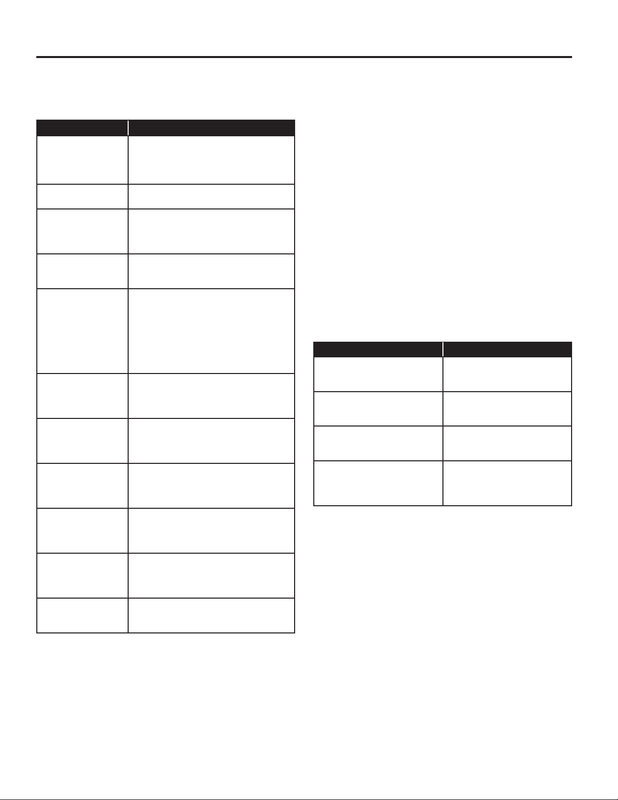
Diagnostic Codes
If the set-up mode is entered and one of the following has
previously occurred, the appropriate diagnostic code will be
in the display.
Dryer Display Explanation
d 5 Blocked coin 1 or coin drop UI control
circuit failure (coin recognition and
customer display disabled while
blockage persists).
d 9 Voltage detected below 90 VAC for
8 seconds.
d 13 Blocked coin 2 or coin drop UI control
circuit failure (coin recognition and
customer display disabled while
blockage persists).
d 16 Not receiving communications from
installed debit card reader in Enhanced
(Generation 2) Debit mode.
F 01 Dryer motor control circuit error
(cycles and price display disabled until
diagnostic code is manually cleared).
The control doesn’t know if the motor
relay is bad (stuck on), the motor relay
drive circuit is bad (shorted), causing
the motor relay to stay on, or the
motor relay feedback circuit is bad.
F 22 Exhaust thermistor open, temperature
drops below 18°F (>50 k) for 1
minute in Run mode, or immediately
in Factory Diagnostic Mode.
F 23 Exhaust thermistor shorted,
temperature above 250°F (<500) for
1 minute in Run mode, or immediately
in Factory Diagnostic Mode.
F 70 UI is not receiving communications
from CCU (cycles and price display
disabled while error persists or is
manually cleared).
F 71 CCU is not receiving communications
from UI (cycles and price display
disabled while error persists
or is manually cleared).
F 73 UI Microprocessor is not able to read
or verify EEPROM (cycles and price
display disabled until diagnostic code
is manually cleared).
F 74 UI EEPROM memory is a CRC failure
(cycles and price display disabled until
diagnostic code is manually cleared).
Dryer Diagnostic Mode
This mode is entered by pressing COLORS/DELICATES for one
second while in either of the set-up codes 6.xx or 7.xx or with a
diagnostic code present. Diagnostic codes are cleared on entry
and all display segments should ash. If a diagnostic code
persists, it must be corrected before the diagnostic cycle
can be entered.
All Models:
With all segments ashing, the diagnostic cycle is started
by pressing the PERM PRESS button. The cycle consists
of 7 minutes of heat and 1 minute of cooldown.
The COTTON/WHITES button will increment the diagnostic
cycle minutes up to 99, then roll over to 2 minutes. The
COLORS/DELICATES button will cancel this cycle and
exit the diagnostic mode.
Dryer Help Mode
Dryer help mode is entered by pressing the COTTON/WHITES
button while in special pricing option 2.XX. In help mode, the
software revision is displayed. The help mode is advanced by
pressing the PERM PRESS button. See Help Mode Submenu
below for the order in which items are displayed. Press the
COTTON/WHITES button at any time to exit help mode.
Help Codes
Help Code Description
71 Generation 2 debit card
cycle polling message out
of sequence.
74 Generation 2 debit card
remaining balance message
out of sequence.
75 Generation 2 debit card new
card balance message out
of sequence.
88 Invalid messaging state
found in data acquisition
communications comm_
suprv ( ) routine.
32
Page 33
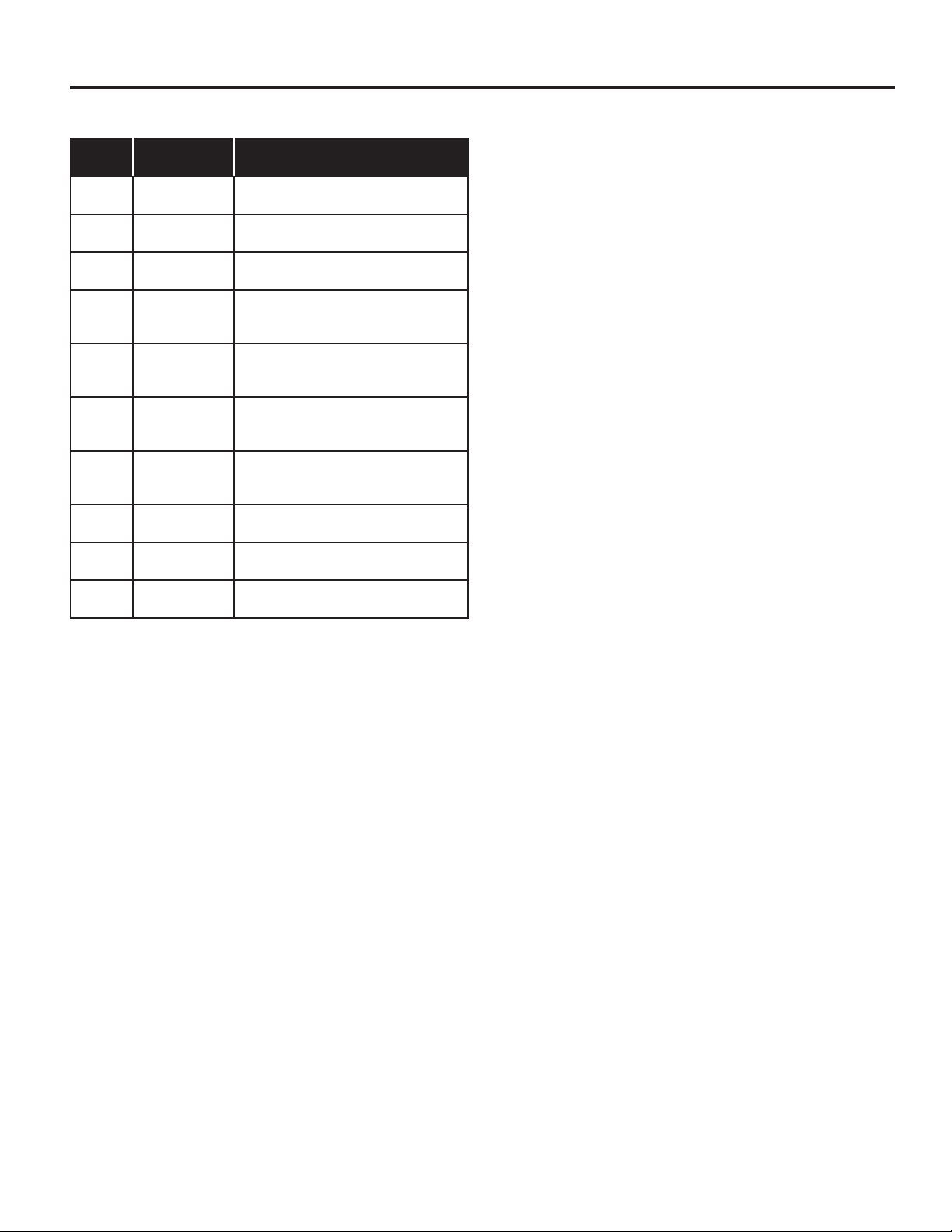
Help Mode Submenu
ELECTRONIC CONTROL SETUP INSTRUCTIONS
Step
1 1h.XX Help Code 1, where XX is the help
2 2h.XX Help Code 2, where XX is the help
3 3h.XX Help Code 3, where XX is the help
4 1.X## Error history code 1, where X is
5 2.X## Error history code 2, where X is
6 3.X## Error history code 3, where X is
7 4.X## Error history code 4, where X is
8 SC.XX CCU software revision, where XX is
9 SU.XX UI software revision, where XX is
10 EU.XX UI EEPROM revision, where XX is
Display
Indication
Explanation
code number. *
code number. *
code number. *
the F or d code, and ## is the code
number. **
the F or d code, and ## is the code
number. **
the F or d code, and ## is the code
number. **
the F or d code, and ## is the code
number. **
the software revision number.
the software number.
the EEPROM number.
* To erase the 3 help codes, press COLORS/DELICATES
button.
** The Errors displayed in this section are the history errors that
have occurred in the dryer (not necessarily an error that is in
progress). The current error is displayed in the MANUAL KEY
FUNCTION IN DIAGNOSTIC SUB-MODE.
In help mode, other display symbols and elements are mapped
to reect the state of various inputs and outputs as follows:
All Dryers
*.. . . . . . . . . . . . . . . . .low voltage present (below about 90 VAC)
°(circle above digit) . . . . . . . . . . . . . . . . . . . . . . . . . door closed
OR. . . . . . . . . . . . . . . . . . . . . . . . . . . . . . . motor sensed running
AIR. . . . . . . . . . . . . . . . . . . . . . . . . . . . heater/gas valve relay on
FLUFF. . . . . . . . . . . . . . . . . . . . . . . . . . . . . . . . . . .motor relay on
33
Page 34
WHIRLPOOL® COMMERCIAL LAUNDRY
LIMITED WARRANTY
IF YOU NEED SERVICE:
Contact your authorized Whirlpool® Commercial Laundry distributor. To locate your authorized Whirlpool® Commercial Laundry distributor, call:
1-800-662-3587, or for web inquiries, visit www.WhirlpoolCommercialLaundry.com.
For written correspondence:
®
Whirlpool
WHAT IS COVERED
90 DAY LIMITED WARRANTY
(PARTS AND LABOR)
For 90 days from the original date of purchase, when
this commercial appliance is installed, maintained, and
operated according to the instructions attached to
or furnished with the product, Whirlpool Corporation
(hereafter “Whirlpool”) will pay for factory specified
replacement parts and repair labor to correct defects
in materials or workmanship that existed when this
commercial appliance was purchased.
TWO YEAR LIMITED WARRANTY
(PARTS ONLY)
For the first two years from the original date of
purchase, when this commercial appliance is installed,
maintained, and operated according to the instructions
attached to or furnished with the product, Whirlpool will
pay for factory specified replacement parts to correct
defects in materials or workmanship that existed when
this commercial appliance was purchased.
YOUR SOLE AND EXCLUSIVE REMEDY UNDER THIS
LIMITED WARRANTY SHALL BE PRODUCT REPAIR
AS PROVIDED HEREIN. Whirlpool recommends that
you use an “in network” service provider to diagnose
and repair your Commercial Laundry product.
Whirlpool will not be responsible under this warranty
to provide additional replacement parts as a result of
incorrect diagnosis or repair by an “out of network”
service company. This limited warranty is valid in the
United States or Canada and applies only when the
commercial appliance is used in the country in which
it was purchased. This limited warranty is effective
from the date of the original consumer purchase. Proof
of original purchase date is required to obtain service
under this limited warranty.
IMPLIED WARRANTIES, INCLUDING ANY IMPLIED WARRANTY OF MERCHANTABILITY OR IMPLIED WARRANTY OF FITNESS FOR A
PARTICULAR PURPOSE, ARE LIMITED TO TWO YEARS OR THE SHORTEST PERIOD ALLOWED BY LAW. Some states and provinces do
not allow limitations on the duration of implied warranties of merchantability or fitness, so this limitation may not apply to you. This warranty
gives you specific legal rights, and you also may have other rights that vary from state to state or province to province.
DISCLAIMER OF REPRESENTATIONS OUTSIDE OF WARRANTY
Whirlpool makes no representations about the quality, durability, or need for service or repair of this major appliance other than the
representations contained in this Warranty. If you want a longer or more comprehensive warranty than the limited warranty that comes
with this major appliance, you should ask Whirlpool or your retailer about buying an extended warranty.
LIMITATION OF REMEDIES; EXCLUSION OF INCIDENTAL AND CONSEQUENTIAL DAMAGES
YOUR SOLE AND EXCLUSIVE REMEDY UNDER THIS LIMITED WARRANTY SHALL BE PRODUCT REPAIR AS PROVIDED HEREIN.
WHIRLPOOL SHALL NOT BE LIABLE FOR INCIDENTAL OR CONSEQUENTIAL DAMAGES. Some states and provinces do not allow the
exclusion or limitation of incidental or consequential damages, so these limitations and exclusions may not apply to you. This warranty
gives you specific legal rights, and you also may have other rights that vary from state to state or province to province.
08/16
Commercial Laundry Service Department
2000 N M 63
Benton Harbor, Michigan 49022-2632 USA
90 DAY LIMITED WARRANTY
WHAT IS NOT COVERED
1. All other costs including labor, transportation, shipping, or custom duties for
covered parts.
2. Factory specified replacement parts if this commercial appliance is used for other
than normal, commercial use or when it is used in a manner that is inconsistent to
published user or operator instructions and/or installation instructions.
3. Service calls to correct the installation of your commercial appliance, to instruct
you on how to use your commercial appliance, to replace or repair house fuses,
or to correct external wiring or plumbing.
4. Service calls to repair or replace appliance light bulbs, air filters, or water filters.
Consumable parts are excluded from warranty coverage.
5. Damage resulting from improper handling of product during delivery, theft,
accident, alteration, misuse, abuse, fire, flood, acts of God, improper installation,
installation not in accordance with local electrical or plumbing codes, or use of
products not approved by Whirlpool.
6. Pick up and delivery. This commercial appliance is designed to be repaired on
location.
7. Repairs to parts or systems resulting from unauthorized modifications made to
the commercial appliance.
8. The removal and reinstallation of your commercial appliance if it is installed in an
inaccessible location or is not installed in accordance with published installation
instructions.
9. Damage resulting from exposure to chemicals.
10. Changes to the building, room, or location needed in order to make the
commercial appliance operate correctly.
11. Factory specified replacement parts on commercial appliances with original
model/serial numbers that have been removed, altered, or cannot be easily
determined.
12. Discoloration, rust, or oxidation of stainless steel surfaces.
13. Factory specified replacement parts as a result of incorrect diagnosis or repair
by an “out of network” service company.
The cost of repair or replacement under these excluded circumstances shall
be borne by the customer.
DISCLAIMER OF IMPLIED WARRANTIES
34
Page 35

W10919522B
W10919523B—SP
®
/™ ©2017 Whirlpool. All rights reserved. Used under license in Canada.
®
/™ ©2017 Whirlpool. Tous droits réservés. Emploi sous licence au Canada.
03/17
 Loading...