

Page 1

INSTALLATION
INSTRUCTIONS
Commercial Washer
INSTRUCTIONS
D’INSTALLATION
Laveuse commerciale
TABLE OF CONTENTS
Page
Washer Safety .......................................................................... 2
Tools & Parts ............................................................................ 3
Dimensions .............................................................................. 4
Location Requirements ...........................................................5
Drain System ............................................................................ 6
Electrical Requirements..........................................................7
Installation Instructions .......................................................... 8
Connect Drain Hose ................................................................ 9
Connect Inlet Hoses .............................................................. 10
Level Washer ..........................................................................11
Installing Coin Slide and Coin Box ....................................... 11
Complete Installation ............................................................ 12
Typical Full Load Sizes .......................................................... 12
Washer Maintenance.............................................................13
If You Need Assistance ......................................................... 14
Alternate Parts & Accessories ............................................. 14
Warranty ................................................................................. 15
TABLE DES MATIÈRES
Page
Sécurité de la laveuse ........................................................... 16
Outillage et pièces ................................................................. 17
Dimensions ............................................................................ 18
Exigences d’emplacement ................................................... 19
Système de vidange .............................................................. 20
Spécications électriques .................................................... 21
Instructions d’installation ..................................................... 22
Raccordement du tuyau de vidange .................................... 23
Raccordement des tuyaux d’arrivée d’eau ......................... 24
Établissement de l’aplomb de la laveuse ............................ 25
Installation de la glissière et de la boîte à monnaie ........... 25
Achever l’installation ............................................................. 26
Taille typique des charges complètes ................................. 26
Entretien de la laveuse .......................................................... 27
Si vous avez besoin d’assistance ........................................ 28
Pièces supplémentaires et accessoires .............................. 28
Garantie .................................................................................. 29
W10837712A
W10861398A – SP
www.whirlpoolcommerciallaundry.com
Page 2

WASHER SAFETY
2
Page 3

Tools Needed:
Level Pliers Utility Knife
TOOLS & PARTS
9/16" (14 mm)
Open End Wrench
Flat-Blade Screwdriver
Optional tools:
Flashlight Bucket
Parts Supplied:
Water Inlet Hoses (2) Inlet Hose Washers (4)
Drain Hose with Clamp,
U-Form, and Cable Tie
Service Door Lock Assembly
(coin slide models only)
Coin Slide Decal Kit
(on some models)
3
Page 4

DIMENSIONS
(921 mm)
Non-coin-operated
(
)
(1.080 m)
(933 mm)
16"
(933 mm)
16"
Front View Side View
Screw
locations
361/4"
1"
25 mm
Back View
Non-coin-operated models Coin-operated models
(406 mm)
101/2"
(267 mm)
51/2"
(140 mm)
(406 mm)
101/2"
(267 mm)
27"
(686 mm)
models:
61/4"
(159 mm)
Coin-operated
models:
81/4"
(210 mm)
51/2"
(140 mm)
4
421/2"
371/4"
(946 mm)
63/4"
(171 mm)
41/4"
(108 mm)
27"
(686 mm)
1"
(25 mm)
363/4"
441/2"
(1.130 m)
371/4"
(946 mm)
63/4"
(171 mm)
41/4"
(108 mm)
(686 mm)
27"
363/4"
1"
(25 mm)
Page 5

LOCATION REQUIREMENTS
Selecting the proper location for your washer improves
performance and minimizes noise and possible washer “walk.”
Your washer can be installed in a basement, laundry room, or
recessed area. See “Drain System.”
Companion appliance location requirements should also be
considered.
IMPORTANT: Do not install or store the washer where it will be
exposed to the weather. Do not store or operate the washer in
temperatures at or below 32°F (0°C). Some water can remain in
the washer and can cause damage in low temperatures. Proper
installation is your responsibility.
You will need:
n A water heater set to 120°F (49°C).
n A grounded electrical outlet located within 4 ft. (1.2 m) of
power cord on back of washer. See “Electrical Requirements.”
n Hot and cold water faucets located within 4 ft. (1.2 m) of
hot and cold water ll valves on washer, and water pressure
of 20-100 psi (138-690 kPa). A pressure reduction valve
should be used in the supply line where inlet pressure
entering the building exceeds 100 PSI (690 kPa) to avoid
damage to the washer mixing valve.
n Single washer installations require 12" (300 mm) minimum
risers to provide an air cushion and avoid noise and damage
to valves.
n A level oor with maximum slope of 1" (25 mm) under entire
washer. Installing on carpet is not recommended.
n
Floor must support washer’s total weight (with water and load)
of 315 lbs (143 kgs).
n A oor drain under the bulkhead. Prefabricated bulkheads
with electrical outlets, water inlet lines, and drain facilities
should be used only where local codes permit.
Recessed Area or Closet Installation
This washer may be installed in a recessed area or closet.
The installation dimensions shown are the minimum spaces
allowable. Additional spacing should be considered for ease of
installation and servicing. Companion appliance spacing should
be considered.
Minimum installation spacing
5
Page 6
DRAIN SYSTEM
8"
(203 mm)
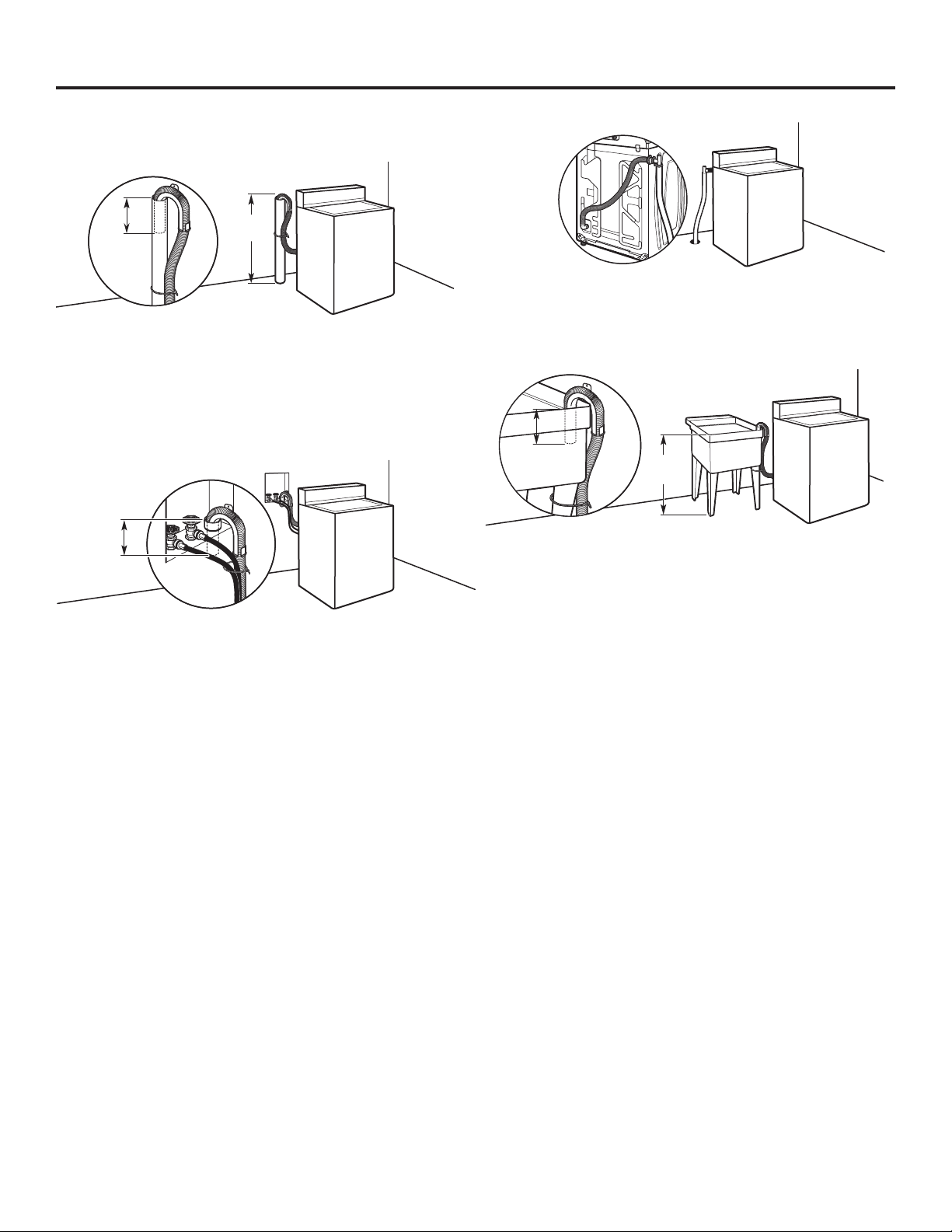
Drain system can be installed using a oor drain, wall standpipe,
oor standpipe, or laundry tub. Select method you need.
Floor standpipe drain system
39"
8"
(203 mm)
Minimum diameter for a standpipe drain: 2" (51 mm). Minimum
carry-away capacity: 10 gal. (38 L) per minute. Top of standpipe
must be at least 39" (990 mm) high; install no higher than
96" (2.44 m) from bottom of washer.
(990 mm)
Wall standpipe drain system
8"
(203 mm)
Floor drain system
Floor drain system requires a Siphon Break Kit (Part Number
285320). Minimum siphon break: 28" (710 mm) from bottom
of washer. Additional hoses may be needed.
Laundry tub drain system
39"
(990 mm)
Minimum capacity: 20 gal. (76 L). The top of the laundry tub
must be at least 39" (990 mm) above oor.
See requirements for oor standpipe drain system.
6
Page 7
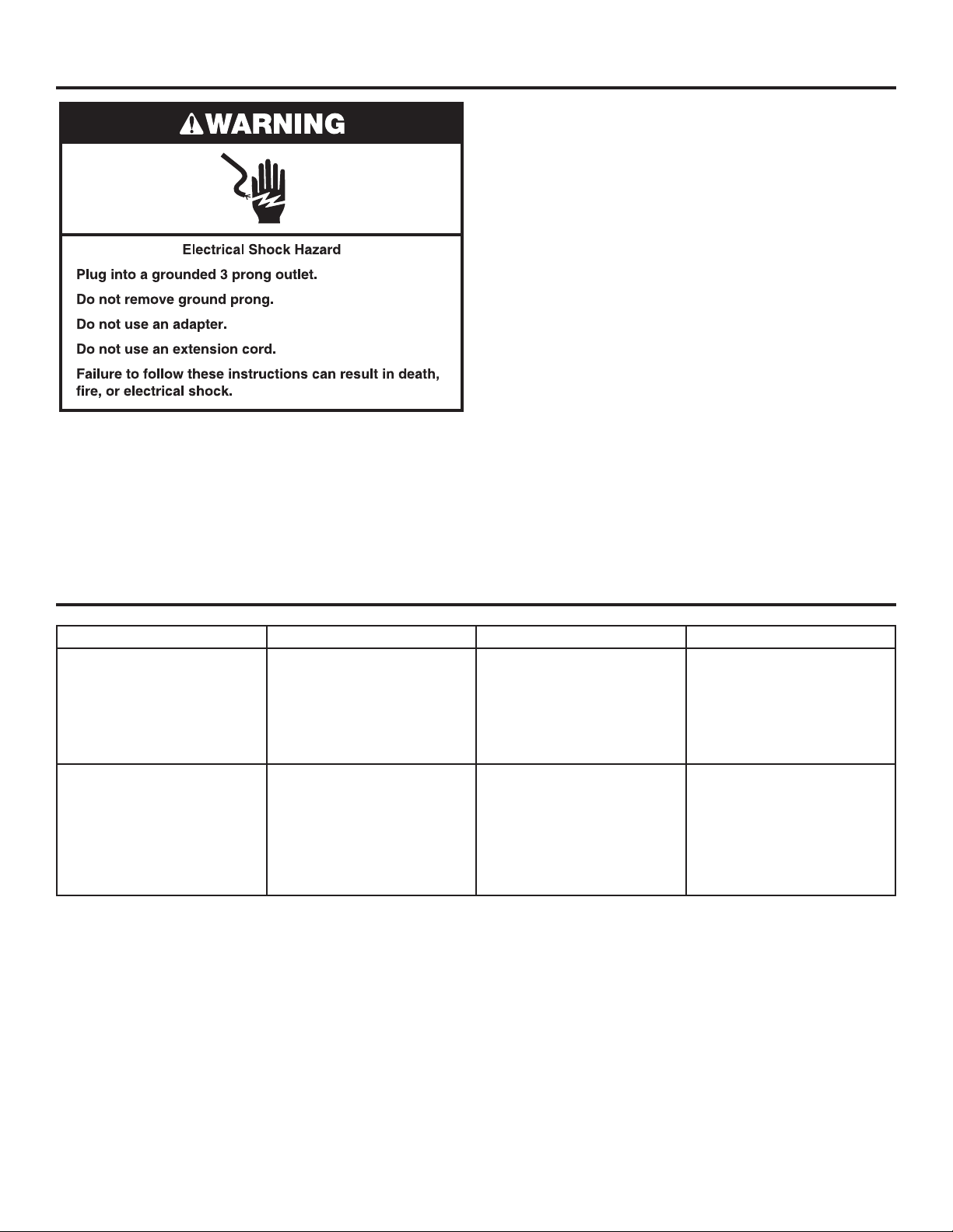
n
A 120 volt, 60 Hz., AC only, 15- or 20-amp, fused electrical supply
is required. A time-delay fuse or circuit breaker is recommended.
It is recommended that a separate circuit breaker serving only
this appliance be provided.
n
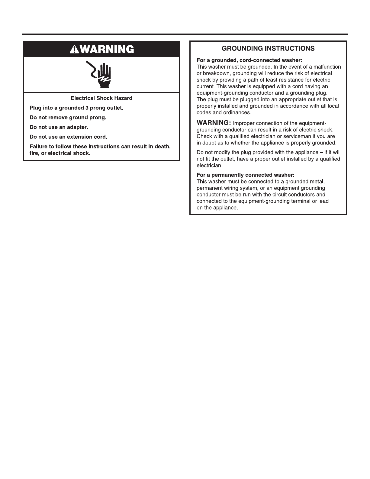
This washer is equipped with a power supply cord having
a 3 prong grounding plug.
n
To minimize possible shock hazard, the cord must be plugged
into a mating, 3 prong, grounding-type outlet, grounded in
accordance with local codes and ordinances. If a mating outlet
is not available, it is the personal responsibility and obligation
of the customer to have the properly grounded outlet installed
by a qualied electrician.
n
If codes permit and a separate ground wire is used, it is
recommended that a qualied electrician determine that
the ground path is adequate.
n
Do not ground to a gas pipe.
n
Check with a qualied electrician if you are not sure the
washer is properly grounded.
n
Do not have a fuse in the neutral or ground circuit.
ELECTRICAL REQUIREMENTS
7
Page 8
INSTALLATION INSTRUCTIONS
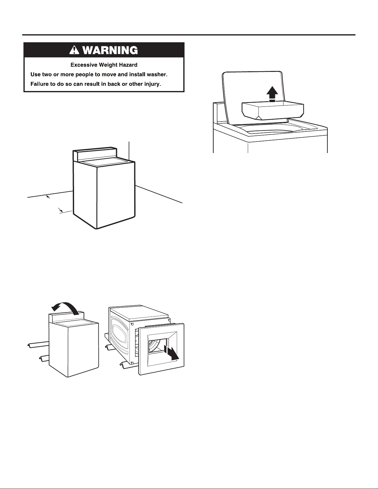
It is necessary to remove all shipping materials for proper
operation and to avoid excessive noise from washer.
1. Move washer to within 4 ft. (1.2 m) of its nal location; it must
be in a fully upright position.
NOTE: To avoid oor damage, set washer onto cardboard
before moving it and make sure lid is taped shut.
48"
(1.2 m)
3. Remove tape from washer lid, open lid, and remove cardboard
packing tray from tub. Be sure to remove all parts from tray.
NOTE: Keep tray in case you need to move washer later.
2. To avoid damaging oor, place cardboard supports from
shipping carton on oor behind washer. Tip washer back
and place on cardboard supports. Remove shipping base.
Set washer upright.
IMPORTANT: Removing shipping base is necessary
for proper operation.
NOTE: Keep shipping base in case you need to move
washer later.
8
Page 9
CONNECT DRAIN HOSE
Proper routing of the drain hose avoids damage to your oor
due to water leakage.
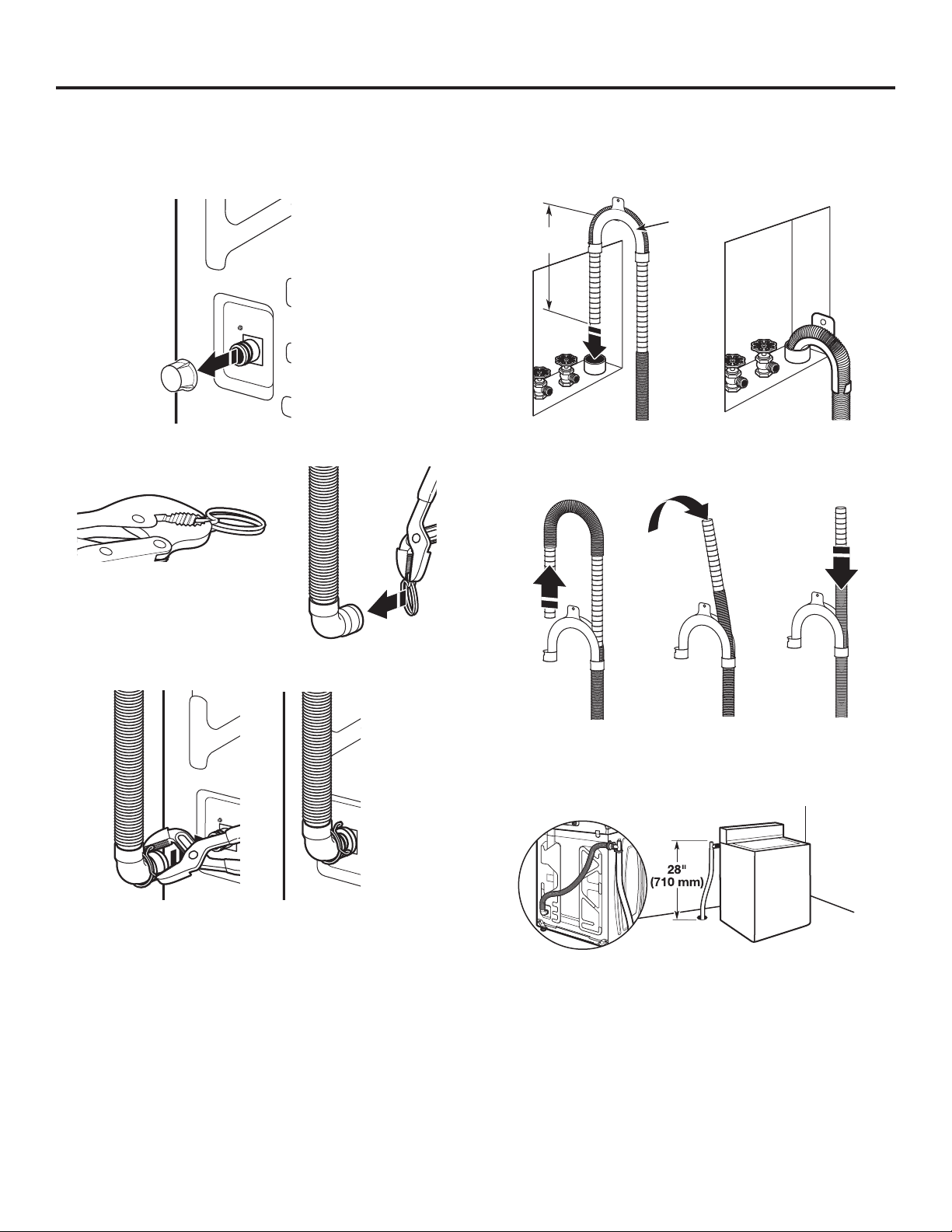
Remove drain hose from the washer drum
1. Remove cap from the washer drain port on the back of
the washer.
2. If clamp is not already in place on elbow end of drain hose,
slide it over end as shown.
5. Place hose into standpipe (shown in picture) or over side
of laundry tub.
IMPORTANT: Drain hose is not to extend more than 8" (203 mm)
inside standpipe; do not force excess hose into standpipe or lay
on bottom of laundry tub. Drain hose form must be used.
Drain
8"
(203 mm)
6. For oor drain installations, you will need to remove the drain
hose form from the end of the drain hose. You may need
additional parts with separate directions. See “Tools and Parts.”
hose
form
3. Squeeze clamp with pliers and slide elbow end of drain
hose onto washer drain port and secure with clamp.
4. The washer drain system can be installed using a oor drain,
wall standpipe, oor standpipe, or laundry tub.
7. The oor drain system requires a siphon break that may be
purchased separately. The siphon break (Part Number 285320)
must be a minimum of 28" (710 mm) from the bottom of the
washer. Additional hoses might be needed.
9
Page 10
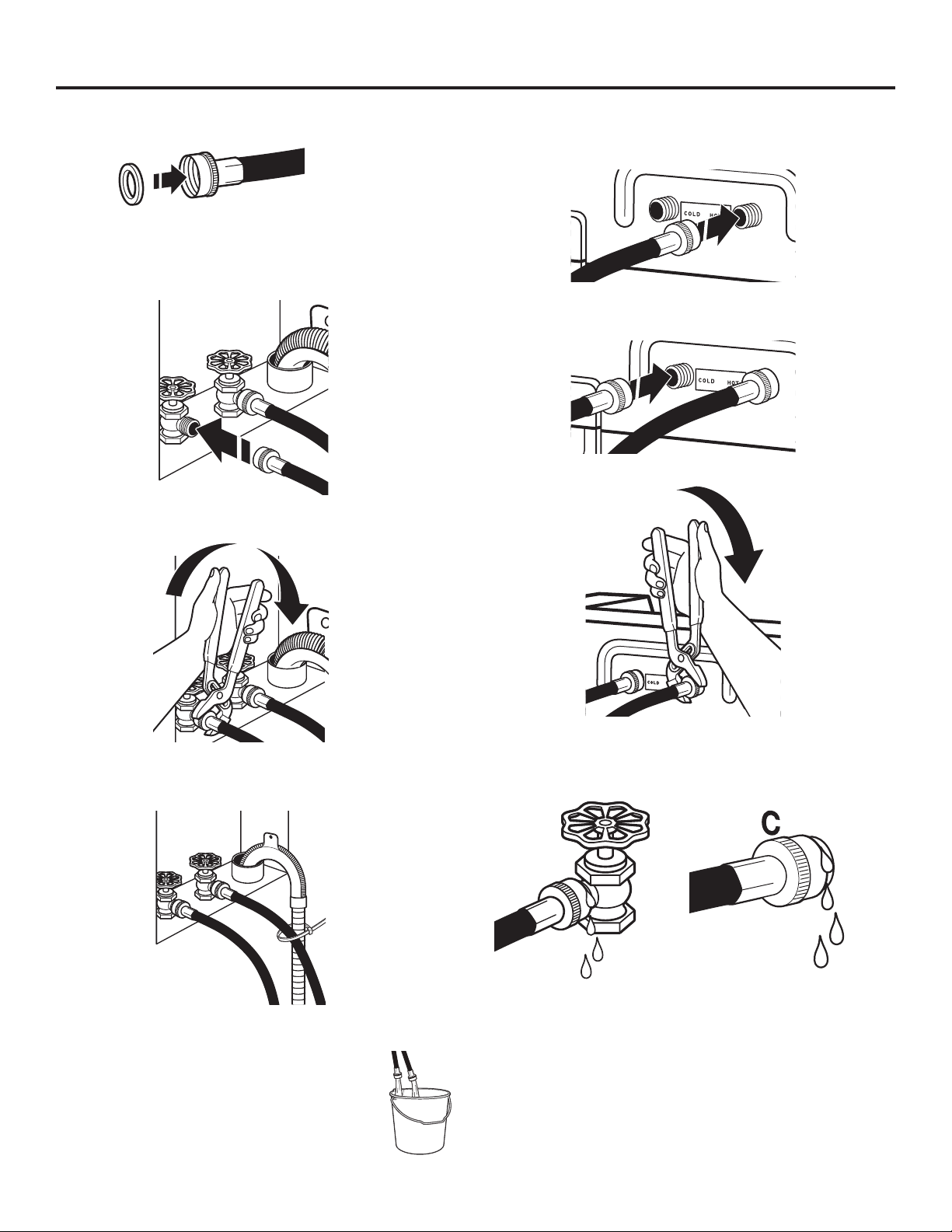
CONNECT INLET HOSES
Insert new hose washers (supplied) into each end of the inlet
hoses. Firmly seat the washers in the couplings.
CouplingWasher
Connect Inlet Hoses to Water Faucets
1. Attach hose to hot water faucet. Screw on coupling until
it is seated on washer. Repeat process for cold water.
2. Use pliers to tighten the couplings an additional
two-thirds turn.
Connect Inlet Hoses to Washer
1. Attach cold water hose to cold water inlet valve marked
with a blue ring. Screw coupling by hand until it is snug.
2. Attach hot water hose to hot water inlet valve marked
with a red ring. Screw coupling by hand until it is snug.
3. Use pliers to tighten couplings an additional two-thirds turn.
IMPORTANT: Do not overtighten or use tape or sealants on valve
when attaching to faucets or washer. Damage can result.
3. Secure drain hose to inlet hose with zip strap.
Clear Water Lines
n Run water through both faucets and inlet hoses,
into a laundry tub, drainpipe, or bucket, to get
rid of particles in the water lines that might clog
the inlet valve screens.
n Check the temperature of the water to make
sure that the hot water hose is connected to the
hot water faucet and that the cold water hose
is connected to the cold water faucet.
NOTE: Do not overtighten. Damage to the valve can result.
4. Turn on water faucets to check for leaks. A small amount
of water may enter washer. It will drain later.
NOTE: Replace inlet hoses after 5 years of use to reduce the
risk of hose failure. Record hose installation or replacement
dates on the hoses for future reference.
Periodically inspect and replace hoses if bulges, kinks, cuts,
wear, or leaks are found.
10
Page 11
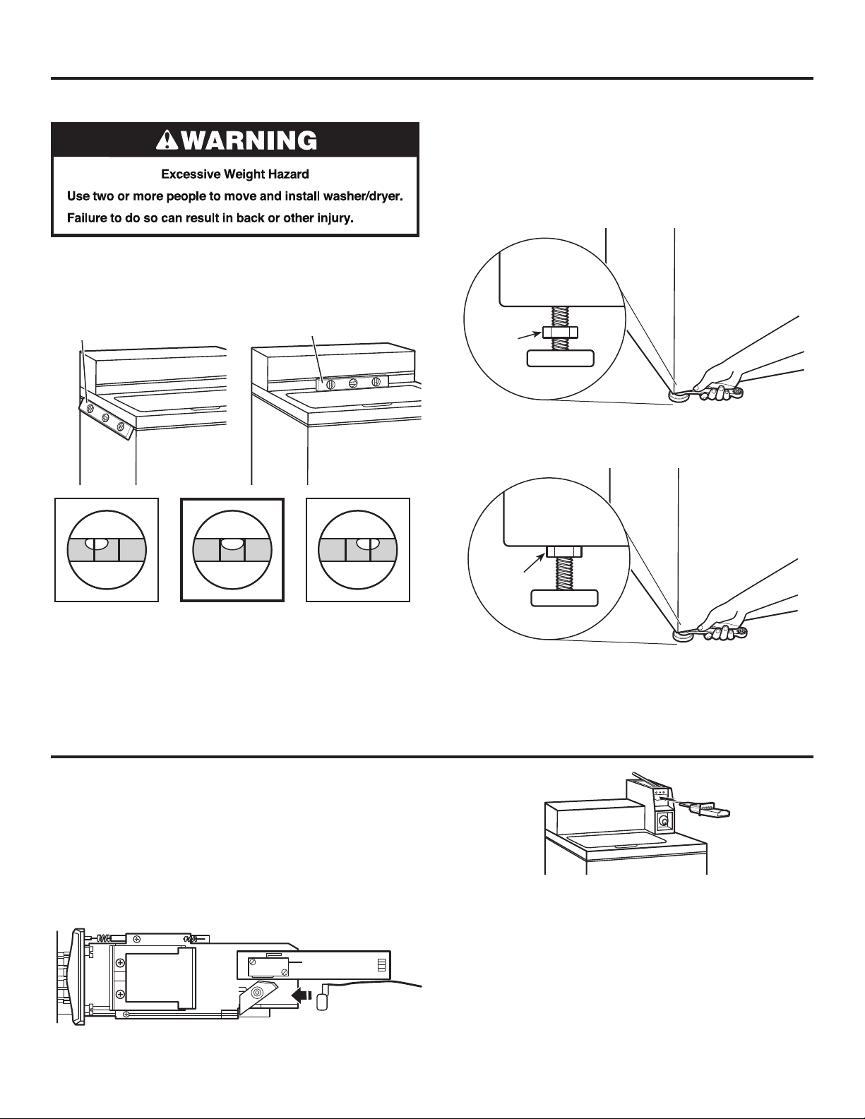
LEVEL WASHER
IMPORTANT: Level washer properly to reduce excess noise
and vibration.
1. Move the washer to its nal location. Place a level on top
edges of washer. Use side seam as a guide to check levelness
of sides. Check levelness of front using lid, as shown. Rock
washer back and forth to make sure all four feet make solid
contact with oor.
Place level here
Place level here
2. Use a 9/16" or 14 mm open-end or adjustable wrench to turn
jam nuts clockwise on feet until they are about 1/2" (13 mm)
from the washer cabinet. Then turn the leveling foot clockwise
to lower the washer or counterclockwise to raise the washer.
Recheck levelness of washer and repeat as needed.
HELPFUL TIP: You may want to prop up front of washer about
4" (102 mm) with a wood block or similar object that will support
weight of washer.
Jam nut
3. When washer is level, use a 9/16" or 14 mm open-end or
adjustable wrench to turn jam nuts counterclockwise on leveling
feet tightly against washer cabinet.
Not Level LEVEL Not Level
INSTALLING COIN SLIDE AND COIN BOX
The coin slide mechanism, service door lock and key, and coin
box lock and key are not included with some models, but can
be obtained from the usual industry sources.
Remove the service door of the meter case by lifting it up
at the back. Install the money-accepting device. (Refer to
manufacturer’s instructions for proper installation.)
A ground connection is needed for the coin slide, which can be
made by connecting the available harness (W10846503) to the
coin slide.
Jam nut
For washer using coin slides, use the adapter kit supplied with
the washer.
Install a lock and cam on the meter case service door. Install the
coin vault with lock and key in the meter case opening.
Ground
connection
11
Page 12
COMPLETE INSTALLATION
Check electrical requirements. Be sure that you have
q
the correct electrical supply and the recommended
grounding method.
Check that all parts are now installed. If there is an extra part,
q
go back through steps to see what was skipped.
Check that you have all of your tools.
q
Check that shipping materials were completely removed
q
from washer.
Dispose of/recycle all packaging materials.
q
Check that the water faucets are on.
q
Check for leaks around faucets and inlet hoses.
q
Remove lm from console and any tape remaining
q
on washer.
Plug into a grounded outlet or connect power.
q
Check that circuit breaker is not tripped or fuse is not blown.
q
Start washer using the payment system (if available)
q
to check that the wash cycle completes without an error
code or water leak.
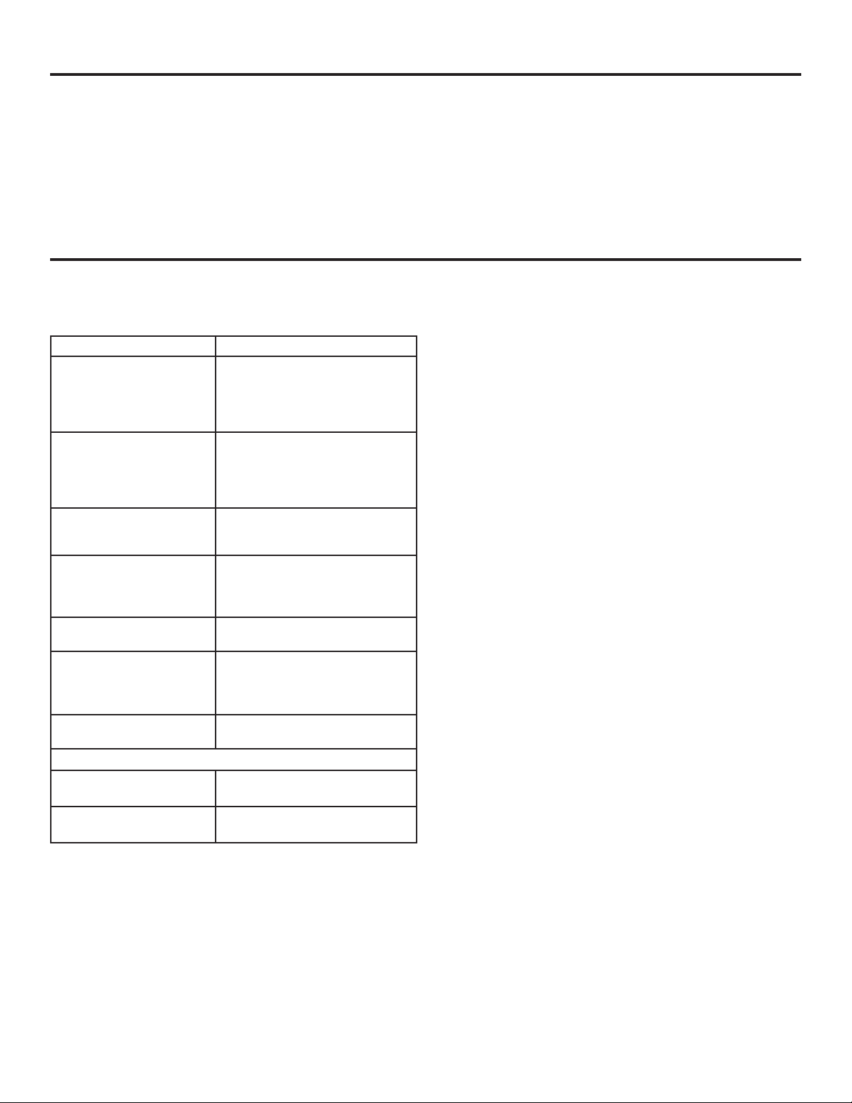
TYPICAL FULL LOAD SIZES
Load Type Loading Suggestion Load Type Loading Suggestion
Mixed Load 3 double sheets
4 pillowcases
6 pairs shorts
8 T-shirts
2 shirts
2 blouses
8 handkerchiefs
Permanent Press 2 double or
1 king size sheet
1 tablecloth
1 dress
1 blouse
2 slacks
3 shirts
2 pillowcases
Heavy Work Clothes 3 pairs pants
3 shirts
1 coverall
4 pairs jeans
1 overall
Knits 3 blouses
4 slacks
6 shirts
4 tops
4 dresses
12
Page 13
WASHER MAINTENANCE
Operating Tips
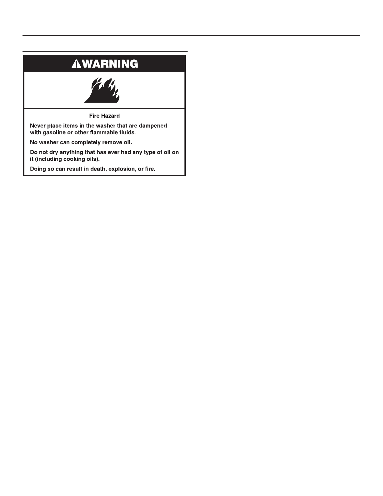
It is recommended that berglass items not be washed in coinoperated washers. If these items are washed in the washer, run
the washer through a complete cycle to rinse any residue away
that might be left in the washer.
Transporting Your Washer
• Shut off both water faucets. Disconnect and drain water inlet
hoses.
• Disconnect drain hose from drain system and drain any
remaining water into a pan or bucket. Disconnect drain hose
from back of washer.
• Unplug power cord.
• Place inlet hoses and drain hose inside washer basket.
• Drape power cord over edge and into washer basket.
• Place packing tray from original shipping materials back inside
washer and reuse shipping base to support the motor and tub.
If you do not have original packaging, place heavy blankets
or towels above basket, between the washer top and the tub
ring. Close lid and place tape over lid and down the front of the
washer. Keep lid taped until washer is moved to new location.
13
Page 14
IF YOU NEED ASSISTANCE
Contact your authorized Commercial Laundry distributor. To locate your authorized Commercial Laundry distributor, or for web
inquiries, visit www.WhirlpoolCommercialLaundry.com.
If you cannot locate your distributor, the Commercial Laundry Support Center will answer any questions about operating or
maintaining your washer not covered in the Installation Instructions.
Just dial 1-800-662-3587 — the call is toll-free.
When you call, you will need the washer model number and serial number. Both numbers can be found on the serial-rating plate
located on the washer.
ALTERNATE PARTS & ACCESSORIES
Your installation may require additional parts. If you are interested
in purchasing one of the items listed here, call the toll-free
number in the “If You Need Assistance” section.
If You Have: You Will Need:
Overhead sewer Standard 20 gal. (76 L) 39"
1" (25 mm) standpipe 2" (51 mm) diameter to
Lint clogged drain Drain Protector, Part Number
Floor drain system Siphon break, Part Number
Drain beyond reach
of drain hose
Water faucets beyond
reach of ll hoses
(990 mm) tall drain tub or utility
sink, sump pump and connectors
(available from local plumbing
suppliers)
1" (25 mm) diameter Standpipe
Adapter, Part Number 3363920.
Connector Kit, Part Number
285835
367031. Connector Kit, Part
Number 285835
285320. Connector Kit (x2), Part
Number 285835. Extension Drain
Hose, Part Number 285863
4 ft. (1.2 m) Drain Hose Extension,
Part Number DRNEXT4
2 longer water ll hoses:
6 ft. (1.8 m) 90° bend hose,
Part Number 76314, 10 ft. (3.0 m)
Part Number 350008
Inlet hoses are sold as a pair
in kit W10575888
Accessories
Washer Drip Trays,
Part Number 8212526
Fabric Softener Dispenser Kit,
Part Number 63594
Whirlpool Corporation, Benton Harbor, Michigan 49022, U.S.A.
14
Page 15
WHIRLPOOL® COMMERCIAL LAUNDRY
LIMITED WARRANTY
IF YOU NEED SERVICE:
Contact your authorized Whirlpool® Commercial Laundry distributor. To locate your authorized Whirlpool® Commercial Laundry distributor, call:
1-800-662-3587, or for web inquiries, visit www.WhirlpoolCommercialLaundry.com.
For written correspondence:
®
Whirlpool
WHAT IS COVERED
90 DAY LIMITED WARRANTY
(PARTS AND LABOR)
For 90 days from the original date of purchase, when
this commercial appliance is installed, maintained, and
operated according to the instructions attached to
or furnished with the product, Whirlpool Corporation
(hereafter “Whirlpool”) will pay for factory specified
replacement parts and repair labor to correct defects
in materials or workmanship that existed when this
commercial appliance was purchased.
YEAR LIMITED WARRANTY
TWO
For the first two years from the original date of
purchase, when this commercial appliance is installed,
maintained, and operated according to the instructions
attached to or furnished with the product, Whirlpool will
pay for factory specified replacement parts to correct
defects in materials or workmanship that existed when
this commercial appliance was purchased.
YOUR SOLE AND EXCLUSIVE REMEDY UNDER THIS
LIMITED WARRANTY SHALL BE PRODUCT REPAIR
AS PROVIDED HEREIN. Whirlpool recommends that
you use an “in network” service provider to diagnose
and repair your Commercial Laundry product.
Whirlpool will not be responsible under this warranty
to provide additional replacement parts as a result of
incorrect diagnosis or repair by an “out of network”
service company. This limited warranty is valid in the
United States or Canada and applies only when the
commercial appliance is used in the country in which
it was purchased. This limited warranty is effective
from the date of the original consumer purchase. Proof
of original purchase date is required to obtain service
under this limited warranty.
IMPLIED WARRANTIES, INCLUDING ANY IMPLIED WARRANTY OF MERCHANTABILITY OR IMPLIED WARRANTY OF FITNESS FOR A
PARTICULAR PURPOSE, ARE LIMITED TO TWO YEARS OR THE SHORTEST PERIOD ALLOWED BY LAW. Some states and provinces do
not allow limitations on the duration of implied warranties of merchantability or fitness, so this limitation may not apply to you. This warranty
gives you specific legal rights, and you also may have other rights that vary from state to state or province to province.
Whirlpool makes no representations about the quality, durability, or need for service or repair of this major appliance other than the
representations contained in this Warranty. If you want a longer or more comprehensive warranty than the limited warranty that comes
with this major appliance, you should ask Whirlpool or your retailer about buying an extended warranty.
YOUR SOLE AND EXCLUSIVE REMEDY UNDER THIS LIMITED WARRANTY SHALL BE PRODUCT REPAIR AS PROVIDED HEREIN.
WHIRLPOOL SHALL NOT BE LIABLE FOR INCIDENTAL OR CONSEQUENTIAL DAMAGES. Some states and provinces do not allow the
exclusion or limitation of incidental or consequential damages, so these limitations and exclusions may not apply to you. This warranty
gives you specific legal rights, and you also may have other rights that vary from state to state or province to province.
08/16
(PARTS ONLY)
DISCLAIMER OF REPRESENTATIONS OUTSIDE OF WARRANTY
LIMITATION OF REMEDIES; EXCLUSION OF INCIDENTAL AND CONSEQUENTIAL DAMAGES
Commercial Laundry Service Department
2000 N M 63
Benton Harbor, Michigan 49022-2632 USA
90 DAY LIMITED WARRANTY
WHAT IS NOT COVERED
1. All other costs including labor, transportation, shipping, or custom duties for
covered parts.
2. Factory specified replacement parts if this commercial appliance is used for other
than normal, commercial use or when it is used in a manner that is inconsistent to
published user or operator instructions and/or installation instructions.
3. Service calls to correct the installation of your commercial appliance, to instruct
you on how to use your commercial appliance, to replace or repair house fuses,
or to correct external wiring or plumbing.
4. Service calls to repair or replace appliance light bulbs, air filters, or water filters.
Consumable parts are excluded from warranty coverage.
5. Damage resulting from improper handling of product during delivery, theft,
accident, alteration, misuse, abuse, fire, flood, acts of God, improper installation,
installation not in accordance with local electrical or plumbing codes, or use of
products not approved by Whirlpool.
6. Pick up and delivery. This commercial appliance is designed to be repaired on
location.
7. Repairs to parts or systems resulting from unauthorized modifications made to
the commercial appliance.
8. The removal and reinstallation of your commercial appliance if it is installed in an
inaccessible location or is not installed in accordance with published installation
instructions.
9. Damage resulting from exposure to chemicals.
10. Changes to the building, room, or location needed in order to make the
commercial appliance operate correctly.
11. Factory specified replacement parts on commercial appliances with original
model/serial numbers that have been removed, altered, or cannot be easily
determined.
12. Discoloration, rust, or oxidation of stainless steel surfaces.
13. Factory specified replacement parts as a result of incorrect diagnosis or repair
by an “out of network” service company.
The cost of repair or replacement under these excluded circumstances shall
be borne by the customer.
DISCLAIMER OF IMPLIED WARRANTIES
15
Page 16

W10837712A
W10861398A – SP
®/TM
© 2016 Whirlpool. All rights reserved.
Used under license in Canada.
®/TM
© 2016 Whirlpool. Tous droits réservés.
Emploi sous licence au Canada.
09/2016
 Loading...