

Whirlpool Cabrio 5610 Series, Cabrio 5700 Series, Cabrio 5500 Series, Cabrio 5550 Series, Cabrio 5810 Series Service Manual
...
FOR SERVICE TECHNICIAN ONLY - DO NOT REMOVE OR DESTROY
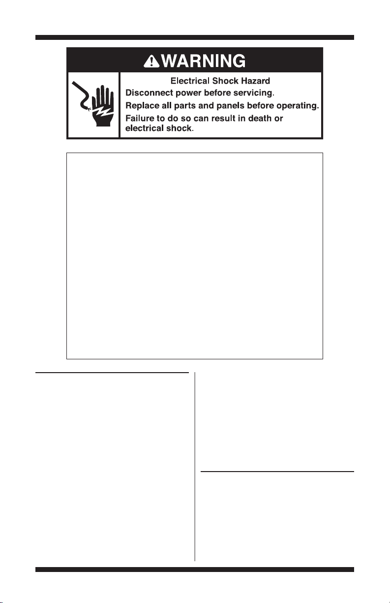
IMPORTANT
Electrostatic Discharge (ESD)
Sensitive Electronics
ESD problems are presenteverywhere. ESD may damage or weaken the
machinecontrol electronics.Thenew control assemblymayappearto workwell
after repair is finished, but failure may occur at a later date due to ESD stress.
■
Use an anti-static wrist strap.Connect wrist strap to green ground
connection point or unpainted metalin the appliance.
■
Touch your finger repeatedly to a greenground connection pointor
unpainted metal in the appliance.
■
Before removingthe partfrom its package, touch the anti-static bag
to a greenground connection pointor unpaintedmetal in the appliance.
■
Avoid touching electronicparts or terminal contacts; handle machine
control electronics by edgesonly.
■
Whenrepackaging failed machine controlelectronics in anti-static bag,
observe above instructions.
-OR-
DIAGNOSTIC GUIDE
■
Before servicing, check the following:
■
Makesure there is poweratthe wall outlet.
■
Has a household fuse blown or circuit breaker
■
tripped? Wasa regularfuse used? Use a timedelay fuse.
■
Is dryer vent properly installedand clear of lint
■
or other obstructions?
■
All tests/checks should be madewith
a VOM(volt-ohm-milliammeter) or DVM
(digital-voltmeter) having a sensitivity
of 20,000 Ω per volt DC or greater.
■
Check all connections before replacing
components.Look forbrokenorloose wires,
failed terminals,orwires notpressed into
SERVICE DIAGNOSTIC MODE ENTRY
These tests allow factoryor service personnel
to testand verify all inputs to the machine control
electronics. Youmay want to do a quick and
overall checkup of the dryerwith these tests
before going to specific troubleshooting tests.
connectors far enough.
PART NO. W10417013C PAGE 1
A potentialcause ofa controlnotfunctioningis
corrosiononconnections.Observeconnections
and checkforcontinuity withan ohmmeter.
Connectors: Look at top of connector. Check
for brokenor loose wires.Check for wires not
pressed into connector far enough to engage
metal barbs.
Resistance checks must be made with dryer
unplugged or powerdisconnected.
FOR SERVICE TECHNICIAN ONLY - DO NOT REMOVE OR DESTROY
ACTIVATING THE SERVICE
DIAGNOSTIC MODE
1. Be sure thedryer is in standbymode
(plugged in with allindicatorsoff,or with only
the DONE [on some models] or DRY[on some
models] indicator on).
2. Select any three buttons and follow the steps
below,using the same buttons (rememberthe
buttons and the order that the buttons were
pressed):
Within 8 seconds,
Press and Release the 1st selectedbutton,
Press and Release the 2nd selectedbutton,
Press and Release the 3rd selectedbutton;
Repeat this3 button sequence 2 more times.
3. If this test mode has been entered
successfully,all indicators on the console are
illuminated for 5 seconds, with somemodels
showing
88 in the EstimatedTime Remaining
two-digit display. If there areno saved fault
codes,all indicators on the console will
momentarily turn off,thenonly the seven
segment display (on somemodels) willcome
backon and display
onlythe WET indicator will comeon and stay
on constantly.
SERVICE DIAGNOSTIC MENU TABLE
1st Button Momentary press ActivatesUser Interface/
2nd Button Momentary press TripleBeep
3rd Button Momentarypress DisplaysNextErrorCode
Unsuccessful Activation
If entry into diagnostic mode is unsuccessful,
refer to the following indications and actions:
Indication 1:
turns on.
Action:
Select any cycle.
If indicators comeon, try to changethe
function for the three buttons used to activate
the diagnostic test mode.
88,and,on other models,
Button Press Function Behavior
Press and hold Exits Service Diagnostics
for 5 secs.
Press and hold TripleBeep
for 5 secs.
Press and hold Clears the ErrorCodes
for 5 secs.
None of the indicators or display
Control SystemTest
If any button fails to change the function,
something is faulty with the button,and it will
not be possible to enter the diagnostic mode
using that button. Replace the user interface
and housing assembly.See Accessing &
Removingthe ElectronicAssemblies,page 23.
If no indicators comeon after selecting the
cycle,go to TEST #1,page 14.
Indication 2:
Console indicators begin
flashing immediately.
Action:
If console indicators begin flashing on
and off immediately, replace the user interface.
SeeAccessing & Removing the Electronic
Assemblies,page 23.
Activation With Saved Fault Codes
(models with seven segment display)
If there is a saved fault code, it will be flashing
in the display.Review the Fault/Error Codes table,
page4, for the recommended procedure.
If there is nosaved fault code,
88 will be displayed.
(models without seven segment display)
If there is a saved fault code, only theWET
indicator will be flashing.Review the Fault/Error
Codes table for the recommended procedure.
Fault/Error Code Display Method
(models with seven segment display)
Fault codes are displayed by alternately showing
F# and E#.All fault codes have an F# and an E#.
The F# indicates the suspect System/Category.
The E# indicates the suspect Componentsystem.
(models without seven segment display)
Fault codes are displayed by a series of flashes of
theWET indicator.All fault codeshave an F# and
an E#.The first set of 0.5 second flashes should
be counted and used as the F#.The F# indicates
the suspect System/Category.The second set of
0.5 secondflashes should againbe counted and
usedas the E#.The E# indicates thesuspect
Component system.The transition from the F# to
the E# is indicated by a 2 second pause.After the
E# is displayed,there will be a 5 secondpause
before the F# is flashed again.
Below showshow F3E6 would be displayed:
3 flashes ➔ 2 second pause➔ 6 flashes ➔ 5 second pause
PAGE 2

FOR SERVICE TECHNICIAN ONLY - DO NOT REMOVE OR DESTROY
Advancing Through Saved Fault/
Error Codes
Procedure for advancingthrough savedfaultcodes:
Press and release Most
the 3rd button beep recent fault
usedto activatetonecodeis
Service Diagnostics displayed.
Repeat
Repeat
Repeat
Repeat
Up to four Fault/Error codes may be stored.
Whenthe oldest fault code is displayed,additional
presses of the 3rd button willresult in a triple
beep, then display of (or cycling back to) the most
recent fault code. If eachpress of the 3rd button
results in a triple beep and the display shows
(on modelswith seven segment display) or the
WET indicator is constantly lit(on models without
seven segment display), no saved fault codes
are present.
beep recent fault
tonecodeis
beep recent fault
tonecodeis
beep recent fault
tonecodeis
Triple beep,then backto
themostrecentfaultcode.
Second most
displayed.
Third most
displayed.
Fourth most
displayed.
88
Clearing Fault Codes
To clear fault codes,enter ServiceDiagnostic mode.
Then press and hold the 3rd button used to enter
Service Diagnostic mode for 5 seconds.Once the
faultcodesaresuccessfully erased,theseven
segmentdisplay will show
sevensegment display) or theWET indicator will
belitconstantly (on models without seven
segmentdisplay).
88 (on models with
PAGE 3
FOR SERVICE TECHNICIAN ONLY - DO NOT REMOVE OR DESTROY
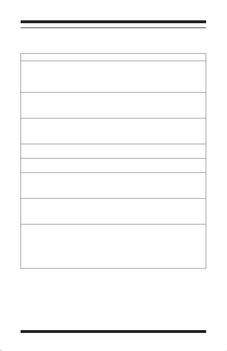
FAULT/ERROR CODES
The fault codes below wouldbe indicated when attempting to starta drying cycle, or after activating the
service diagnostic mode.
Code Description Explanation/Recommended Procedure
pf Power Failure PF indicates that a power failure occurred while the
f1 e 1 Primary Control Failure F1E1indicates a primarycontrol failure.
f2 e 1 Keypad/User F2E1indicates a stuck button or user interface
f3 e 1 ExhaustThermistor Open F3E1indicates that the thermistor is open.
f3 e 2 ExhaustThermistor Shorted F3E2 indicates that the thermistor has shorted.
f3 e 6 Moisture Sensor Open F3E6 indicates that the moisture sensor strip is open.
f3 e 7 Moisture Sensor Shorted F3E7indicates that the moisture sensor striphas
f4e 4 Line VoltageError F4E4 indicates low line voltage detected.
(on some models) dryer was running.
■ Press START/PAUSE to continue the cycle,or press
POWER or POWER/CANCEL (Maytag models) to clear
the display.
■ Replace the machine control electronics.See
Accessing & Removing theElectronicAssemblies,
page23.
Interface Failure mismatch.This fault code will ONLY appear when
in the servicediagnosticmode.
■ See TEST #5, page 22.
■ See TEST #3a,page 19.
■ See TEST #3a,page 19.
This fault code willONLY appear whenin the service
diagnostic mode.
■ See TEST #4, page 20.
shorted.This fault codewill ONLYappearwhen in the
service diagnostic mode.
■ See TEST #4, page 20.
■ Check to see if a household fuse has blown or a
circuit breaker has tripped.Confirm the power cord
is properly installed and plugged intothe power
outlet.Checkthe relay connections on the machine
control electronics. Gas Models Only:Check the P14
connection on the machine control electronics.
PAGE 4
FOR SERVICE TECHNICIAN ONLY - DO NOT REMOVE OR DESTROY
USER INTERFACE/
CONTROL SYSTEM TEST
Entry Procedure:
Press and release the firstbutton used to activate
Service Diagnostic mode.The following testswill
be available.
NOTE: The Service Diagnostic mode must be
activated before activating the UserInterface/
Control Systemtest; see procedureon page 2.
Active Fault Code Display in User
Interface/Control System Test:
If the display (on models withseven segment
display) or WET indicator (on modelswithout
seven segment display) begins flashing while in
UserInterface/ControlSystemtest,it is displaying
an active fault code. Activefault codes are codes
thatare currently failing.Only one activefault
codecan be displayed at a time.
Diagnostic Test: Console Buttons
and Indicators
Pressing buttons and rotatingthe cycle selector
will turn off the correspondingindicator and
sound a beep as shown in figures 1a to 1f,
Console Diagnostics, pages 7–12. If indicators
failto come on and beep after pressing buttons
and rotating the cycle selector, go to TEST #5,
page22.
NOTE: A second press of the POWER (POWER/
CANCEL on Maytag models) buttonwhile in
Console Buttons and Indicators modeexits the
Service Diagnostic mode and returns the dryer
to standby mode.
Diagnostic Test: Door Switch
(models with seven segment display)
Opening the door should cause a beep and an
alphanumeric number to be displayed. Closing
the door should cause a beep and
88 to be
displayed.
If opening the door fails to cause a beep and
an alphanumeric number to be displayed, go
toTEST #6,page 22.
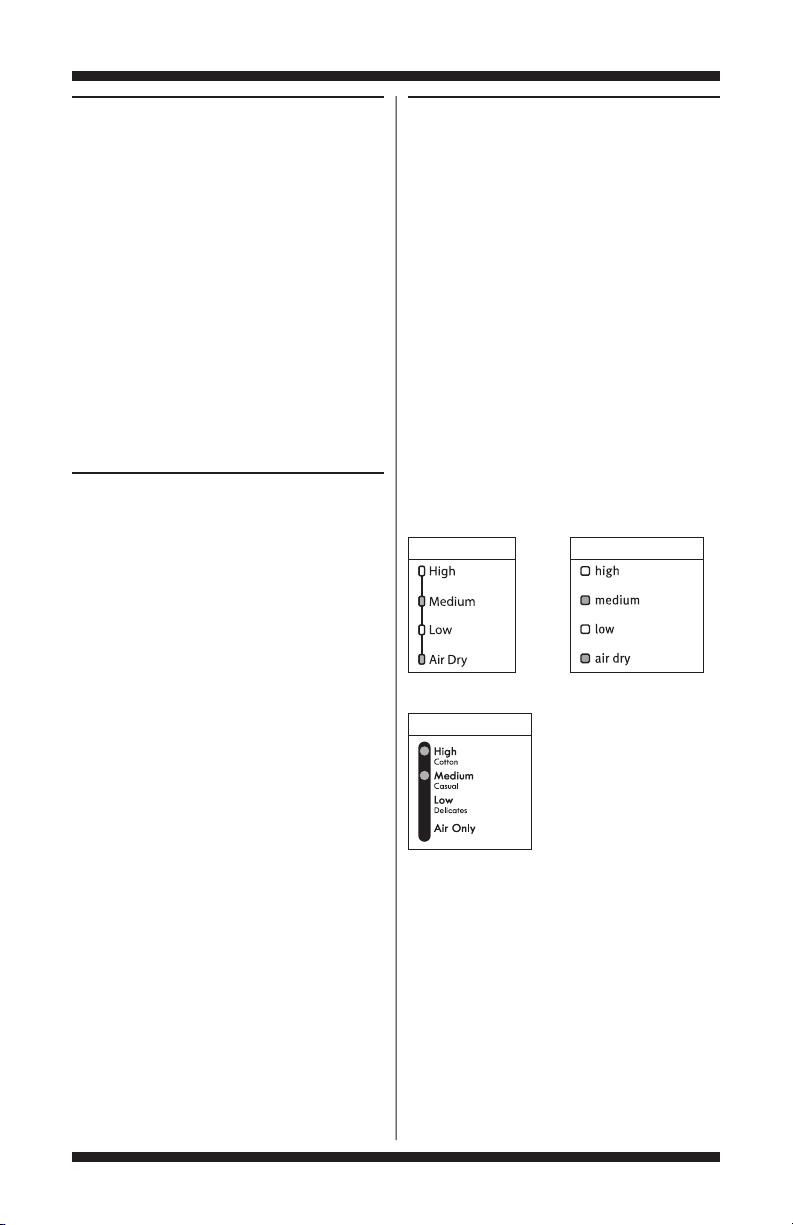
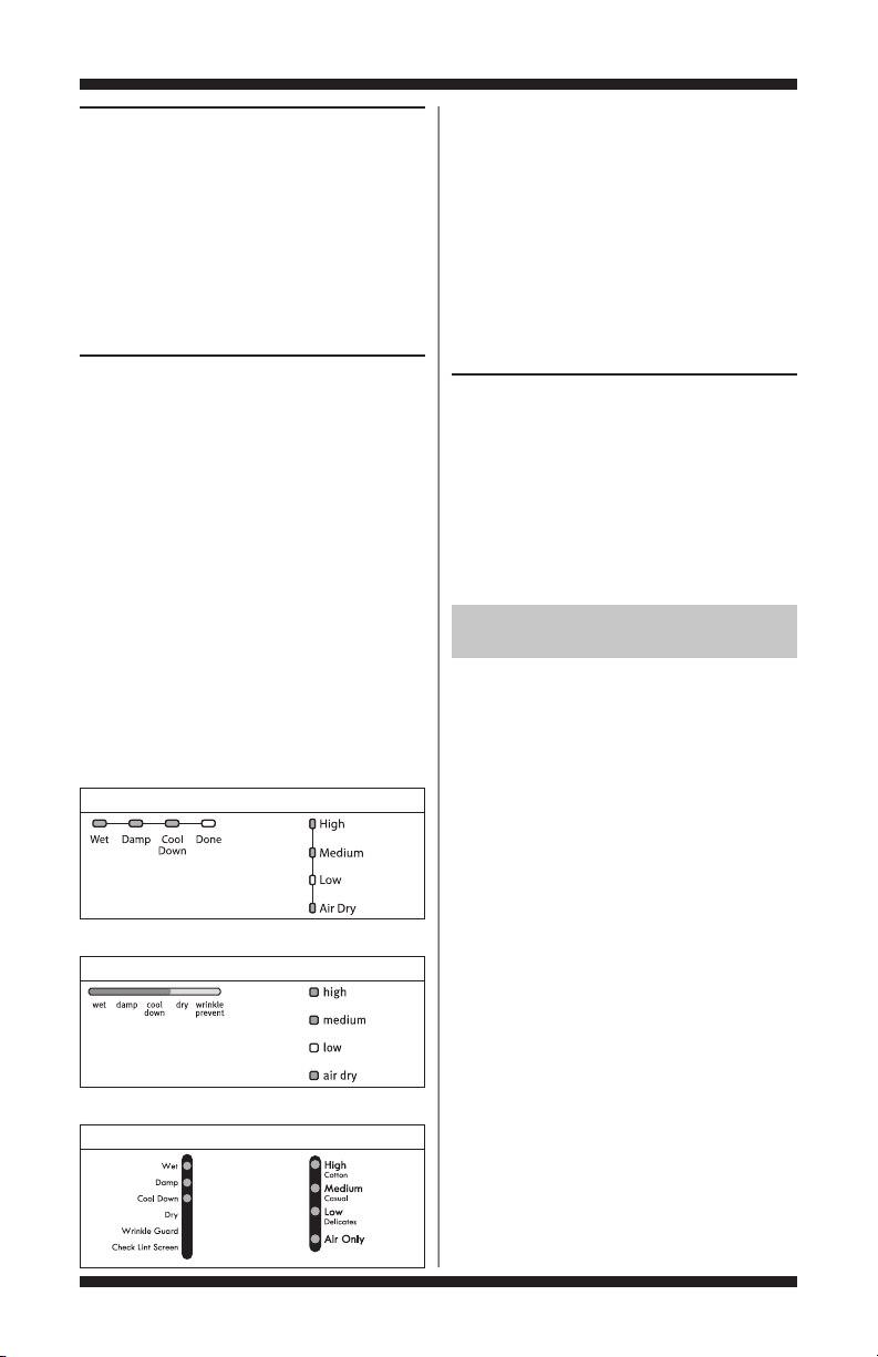
(models without seven segment display)
Whenthe dooris opened, for electric dryers,the
dryer will beep once and the WET statusindicator
will turn on.For gas dryers, the dryer will beep
twice and the DONE or DRY(depending on model)
status indicator will turn on.Withthe door open,
theTEMP,TEMP LEVEL,or DRY TEMP indicators
(depending on model) will be used to display the
Control Software ID.TheTEMP,TEMP LEVEL,or
DRYTEMP indicators will be “On”or“Off”
according to the table below.
Whirlpool Models
Temp Indicators Temp Level Indicators
Kenmore Models
DryTemp Indicators
Maytag Models
If opening the door fails to cause a beep(s),
Control Software ID,or fuel type to be indicated,
go toTEST #6,page 22.
PAGE 5
FOR SERVICE TECHNICIAN ONLY - DO NOT REMOVE OR DESTROY
Diagnostic Test: Moisture Sensor
Openthe doorand locate two metal strips on the
faceof the lintscreenhousing.Bridge thesestrips
witha wet cloth or a finger. If a beep is heard and
an alphanumeric number is displayedon the
console (on models with seven segment display)
or STATUS and/orTEMP,TEMP LEVEL,or DRY
TEMP indicatorschange (on models without
seven segment display), the sensor is OK. If not,
or if a beep tone is heard before bridging the
moisturestrips, go to TEST #4, page20.
Diagnostic Test: Console ID, Motor,
and Heater (models with seven
segment display)
Close the door. Press the STARTbutton.The dryer
will beep and the motorand heater will turn on,
and the display willshow the following Console
ID:7 (Whirlpool 5600 models), 8 (Whirlpool 5700
and 5810 models),2 (Whirlpool 5800 models),
4 (Maytag 600 models), 5 (Maytag700 models),
or a (Kenmoremodels).
(models without seven segment display)
Close the door. Press the STARTbutton.The dryer
will beep and the motorand heater will turn on.
The STATUS and TEMP, TEMP LEVEL, or DRY
TEMP indicatorswill displaythe console ID,and
the indicators shouldbe lit up as indicated in the
table below.
Console ID Indicator Status Table
Whirlpool Models
Status Indicators Temp Indicators
(all models)
While motoris running,pressing the START
button a second time will leave on the motor and
turnoff the heater. A third press of the START
button will turn off both the motor and the heater.
If the Console ID is not displayed,replace
the user interface assembly.See Accessing &
Removingthe Electronic Assemblies, page23.
If the motor does not turnon, go to TEST #2,
page16.
If no heatis detected,go to TEST #3,page 17.
DEACTIVATING TEST MODES
Deactivating the User Interface/
Control System Test
This mode can be exitedby either of the two
methods listedbelow:
1. Pressing thePOWER (POWER/CANCEL
on Maytag models) button twice.
2. Pressing andholding the 1st buttonused to
activatetheService Diagnosticmode for 5 seconds.
DEACTIVATING THE SERVICE
DIAGNOSTIC MODE
Press and hold the 1st button used to enterthe
Service Diagnostic mode for 5 seconds to exit
diagnostics.
Maytag Models
Status Indicators Temp Level Indicators
Kenmore Models
Status Indicators Dry TempIndicators
PAGE 6
FOR SERVICE TECHNICIAN ONLY - DO NOT REMOVE OR DESTROY
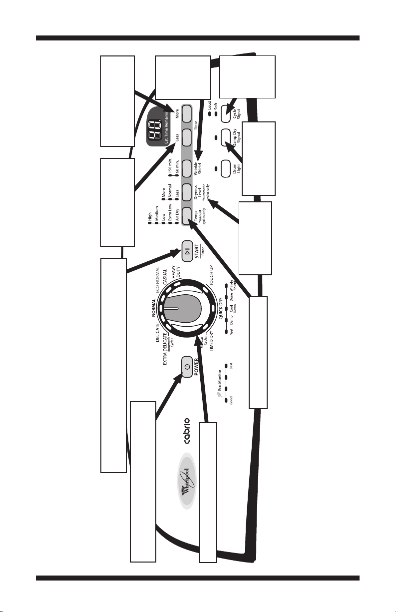
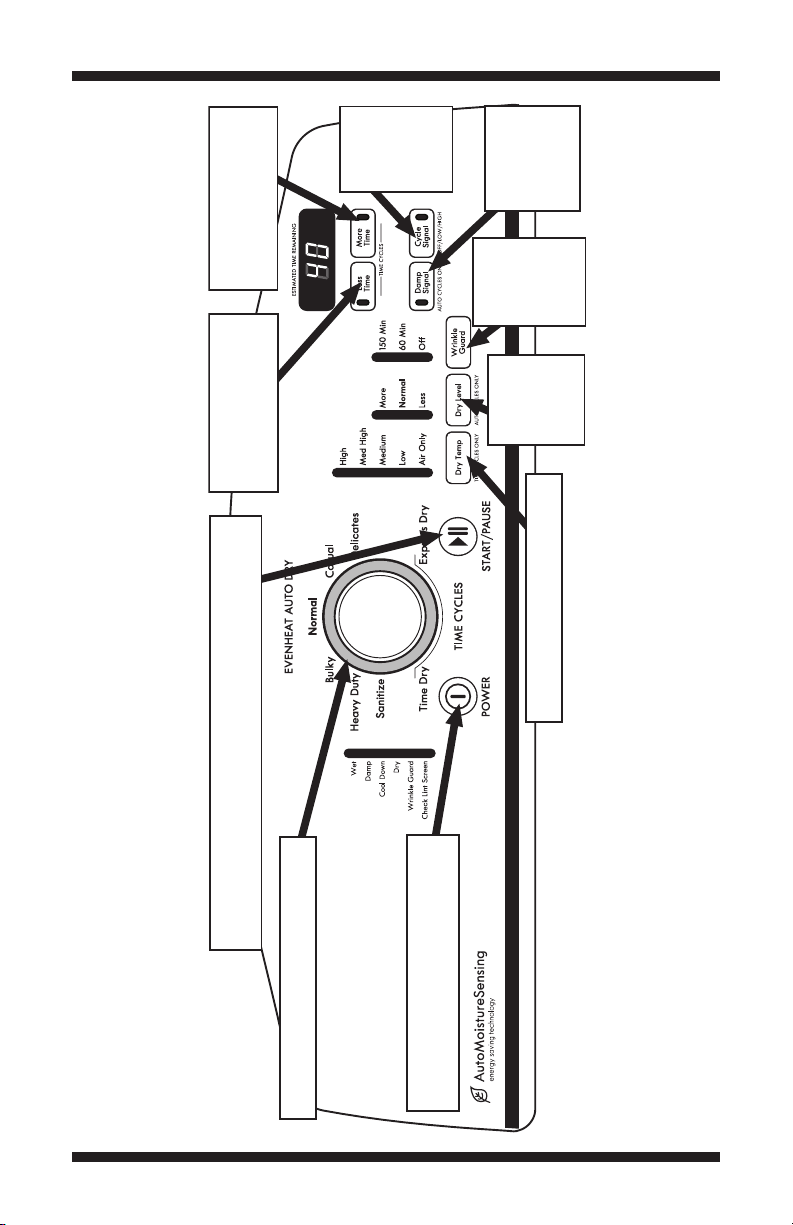
➔➔
Each press
toggles state
of Wrinkle
Shield
indicators.
On Off
or Off On.
➔
➔
Each press toggles the Start/Pause indicator. On Off or Off On.
Press 1 turns on the motor and heater. Press 2 leaves on the motor
and turns off the heater. Press 3 turns off the motor and heater.
➔➔
First press turns off the Status and Eco Monitor
indicators. Second press exits Service Diagnostic
mode and dryer returns to standby mode.
Rotating the encoder will turn indicators on
and off individually. On
➔ Off or Off ➔ On.
Each press toggles state of Temp
indicators. On
➔ Off or Off ➔ On.
Each press toggles
state of Dryness Level
indicators. On
➔ Off
or Off
➔ On.
Each press toggles
state of Damp Dry
Signal indicator.
On Off or Off On.
➔➔
Each press
toggles state
of Cycle
Signal
indicators.
On Off
or Off On.
➔
➔
Each press toggles state of
the right digit of the seven
segment display. On Off
or Off On.
➔
➔
Each press toggles state
of the left digit of the
seven segment display.
On Off or Off On.
➔ ➔
WHIRLPOOL CONTROL PANEL WITH SEVEN SEGMENT DISPLAY (features and appearance may vary)
Figure 1a. Console Diagnostics.
PAGE 7
FOR SERVICE TECHNICIAN ONLY - DO NOT REMOVE OR DESTROY
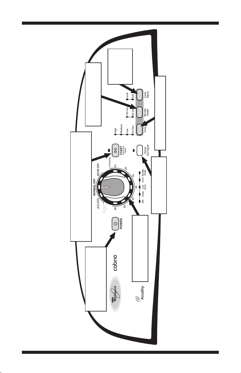
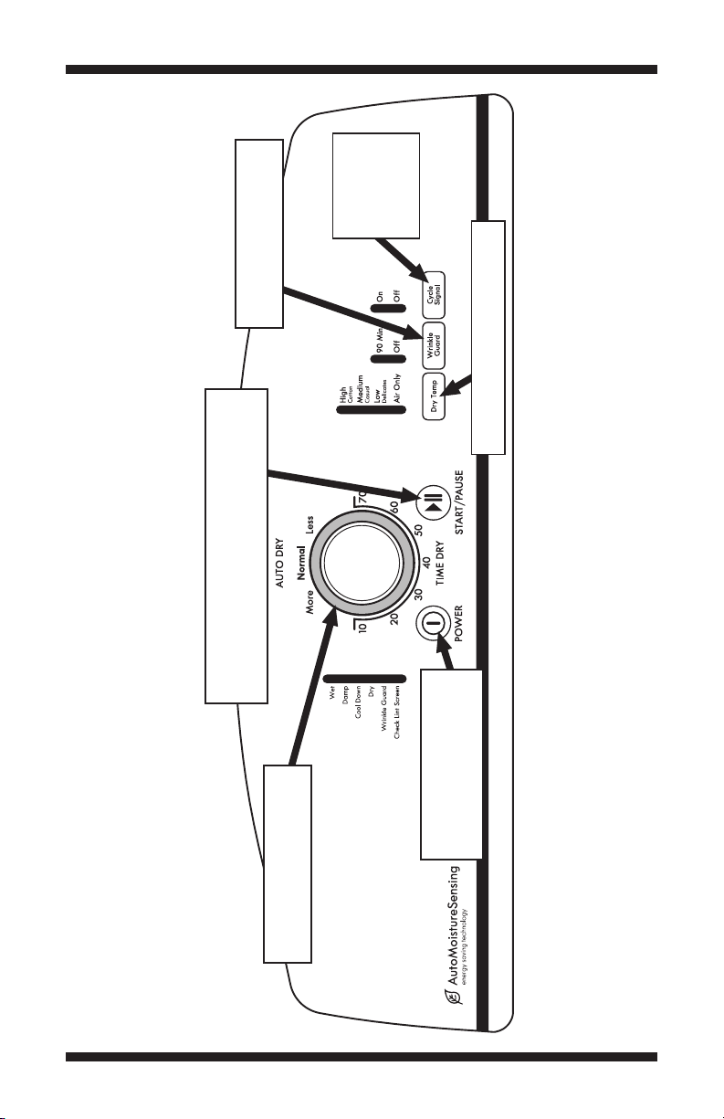
Toggles state of Wrinkle Shield
indicators with each press.
On Off or Off On.
➔➔
First press turns off the Status
indicators. Second press exits
Service Diagnostic mode and
dryer returns to standby mode.
Each press toggles the Start/Pause indicator. On Off
or Off On. Press 1 turns on the motor and heater.
Press 2 leaves on the motor and turns off the heater.
Press 3 turns off the motor and heater.
➔
➔
Rotating the encoder will turn
indicators on and off individually.
On Off or Off On.
➔➔
Toggles state of Damp Dry
indicator with each press.
On Off or Off On.
➔➔
Toggles state of Temp indicators with
each press. On Off or Off On.
➔➔
Toggles state of
Signal indicators
with each press.
On Off or
Off On.
➔
➔
WHIRLPOOL CONTROL PANEL WITHOUT SEVEN SEGMENT DISPLAY (features and appearance may vary)
Figure 1b. Console Diagnostics.
PAGE 8
FOR SERVICE TECHNICIAN ONLY - DO NOT REMOVE OR DESTROY
➔➔
Each press toggles the Start/Pause indicator. On Off or Off On.
Press 1 turns on the motor and heater. Press 2 leaves on the motor
and turns off the heater. Press 3 turns off the motor and heater.
➔➔
First press turns off the Status indicators. Second
press exits Service Diagnostic mode and dryer
returns to standby mode.
Rotating the encoder will turn indicators on
and off individually. On
➔ Off or Off ➔ On.
Each press toggles state of Temp Level
indicators. On
➔ Off or Off ➔ On.
Each press toggles
state of Dryness Level
indicators. On
➔ Off
or Off
➔ On.
Each press toggles
state of Wrinkle
Prevent indicators.
On Off or Off On.
➔➔
Each press
toggles state
of End Signal
indicator.
On Off
or Off On.
➔
➔
Each press toggles state of the
right digit of the seven segment
display. On Off or Off On.
➔ ➔
Each press toggles state of the
left digit of the seven segment
display. On Off or Off On.
➔ ➔
Each press toggles
state of Damp Dry
Signal indicators.
On Off
or Off On.
➔
➔
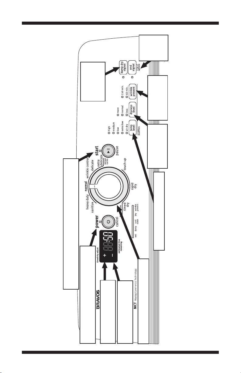
MAYTAG CONTROL PANEL WITH SEVEN SEGMENT DISPLAY (features and appearance may vary)
Figure 1c. Console Diagnostics.
PAGE 9

FOR SERVICE TECHNICIAN ONLY - DO NOT REMOVE OR DESTROY
Toggles state of Wrinkle Prevent
indicators with each press.
On Off or Off On.
➔➔
First press turns off the Status
indicators. Second press exits
Service Diagnostic mode and
dryer returns to standby mode.
Each press toggles the Start/Pause indicator. On Off
or Off On. Press 1 turns on the motor and heater.
Press 2 leaves on the motor and turns off the heater.
Press 3 turns off the motor and heater.
➔
➔
Rotating the encoder will turn
indicators on and off individually.
On Off or Off On.
➔➔
Toggles state of Damp Dry
Signal indicator with each press.
On Off or Off On.
➔➔
Toggles state of Temp Level indicators
with each press. On Off or Off On.
➔➔
Toggles state of
End Signal indicators
with each press.
On Off or Off On.
➔➔
MAYTAG CONTROL PANEL WITHOUT SEVEN SEGMENT DISPLAY (features and appearance may vary)
Figure 1d. Console Diagnostics.
PAGE 10
FOR SERVICE TECHNICIAN ONLY - DO NOT REMOVE OR DESTROY
➔
Each press toggles the Start/Pause indicator. On Off or Off On.
Press 1 turns on the motor and heater. Press 2 leaves on the motor
and turns off the heater. Press 3 turns off the motor and heater.
➔➔
First press turns off the Status indicators.
Second press exits Service Diagnostic
mode and dryer returns to standby mode.
Rotating the encoder will turn indicators on
and off individually. On
➔ Off or Off ➔ On.
Each press toggles state of Dry Temp
indicators. On
➔ Off or Off ➔ On.
Each press
toggles state
of Dry Level
indicators.
On
➔ Off
or Off
➔ On.
Each press
toggles state
of Damp Signal
indicator.
On Off or
Off On.
➔
➔
Each press
toggles state
of Cycle
Signal
indicator.
On Off
or Off On.
➔
➔
Each press toggles state of
the right digit of the seven
segment display. On Off
or Off On.
➔
➔
Each press toggles state
of the left digit of the
seven segment display.
On Off or Off On.
➔ ➔
Each press
toggles state
of Wrinkle
Guard
indicators.
On Off
or Off On.
➔
➔
KENMORE CONTROL PANEL WITH SEVEN SEGMENT DISPLAY (features and appearance may vary)
PAGE 11
Figure 1e. Console Diagnostics.
FOR SERVICE TECHNICIAN ONLY - DO NOT REMOVE OR DESTROY
Toggles state of Wrinkle Guard
indicators with each press.
On Off or Off On.
➔➔
First press turns off the Status
indicators. Second press exits
Service Diagnostic mode and
dryer returns to standby mode.
Each press toggles the Start/Pause indicator.
On Off or Off On. Press 1 turns on the motor
and heater. Press 2 leaves on the motor and turns
off the heater. Press 3 turns off the motor and heater.
➔➔
Rotating the encoder will turn
indicators on and off individually.
On Off or Off On.
➔➔
Toggles state of Dry Temp indicators
with each press. On Off or Off On.
➔➔
Toggles state
of Cycle Signal
indicators with
each press.
On Off or
Off On.
➔
➔
KENMORE CONTROL PANEL WITHOUT SEVEN SEGMENT DISPLAY (features and appearance may vary)
Figure 1f. Console Diagnostics.
PAGE 12

FOR SERVICE TECHNICIAN ONLY - DO NOT REMOVE OR DESTROY
TROUBLESHOOTING GUIDE Some tests will require accessing components.
Problem Possible Cause/Test
NOTE: Possible Cause/Tests MUST be performed
in the sequence shown for each problem.
Won’t power up. (No response 1. Supply connections. See TEST #1, page 14.
when buttons are pressed.)
Won’t start cycle when Start 1. If number display flashes, check to be sure the
button is pressed. door is completely shut, and press and hold down
Won’t shut off when expected. 1. Check START/PAUSE button. See TEST #5,
Control won’t accept selections. User interface and housing assembly.
Won’t heat. 1. Check installation.
Heats in air cycle. Heater. See TEST #3, page 17.
Shuts off before clothes are dry. 1. Check the dryness level (dry level on Kenmore
2. Unplug dryer or disconnect power. Check
harness connections.
3. User interface and housing assembly.
See TEST #5, page 22.
START for about 1 second.
2. See TEST #2, page 16.
3. See TEST #6, page 22.
page 22.
2. User interface and housing assembly.
See TEST #5, page 22.
3. Moisture sensor. See TEST #4, page 20.
See TEST #5, page 22.
2. Unplug dryer or disconnect power. Check
harness connections.
3. Heater. See TEST #3, page 17.
models) setting for auto cycles.
2. Check for full lint screen.
3. Check for clogged vent.
4. Moisture sensor. See TEST #4, page 20.
5. Dryness level (dry level on Kenmore models)
adjust. See TEST #4a, page 21.
PAGE 13
FOR SERVICE TECHNICIAN ONLY - DO NOT REMOVE OR DESTROY
COM
N
L1
If neither of the plug terminals havecontinuity
TROUBLESHOOTING TESTS
NOTE: These checks are done with the dryer
unplugged or disconnectedfrom power.
TEST #1 Supply Connections
This test assumes that proper voltage is present
at the outlet,and for U.S.installations, a visual
inspection indicates that the power cord is
securely fastened to the terminal block (electric
dryer) or wire harness connection (gas dryer).
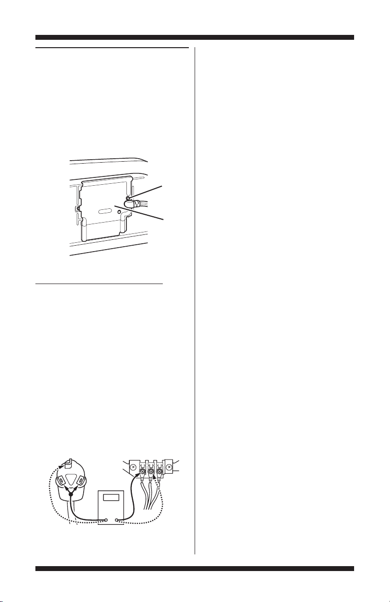
Remove
Screw
Cover
Plate
Figure 2. Remove the cover plate.
ELECTRIC DRYER (U.S. Installations):
1. Unplug dryer or disconnectpower.
2. Remove the cover plate from the back of the
console panel on the dryer. See figure 2.
3. With an ohmmeter, check for continuity
between the neutral (N) terminal of the plug and
the centercontact on the terminalblock. See
figure 3a.
If there is no continuity, replace the power
cordand testthe dryer.
If there is continuity, go to step 4.
4. In a similar way, check which terminal of the
plug is connected to the left-mostcontact on the
terminalblockand make a note of it.Thiswill be
L1(black wire) inthewiringdiagram.Seefigure3a.
Power Cord
Plug
Terminal Block
withthe left-most contact of the terminal block,
replace the power cord and test the dryer.
5. Access the machine control electronics
without disconnecting any wiringto the control
board.See Accessing & Removing the Electronic
Assemblies,page 23.
6. With an ohmmeter, check for continuity
between the L1 terminal of the plug (found in step
4) and P9-2 (black wire) on the machine control
board.See figure 13,page 24.
If there is continuity, go to step 7.
If there is no continuity, check that wires to the
terminalblockare mechanically secure. If so,
replace the main wire harness and test the dryer.
7. Checkfor continuity between the neutral (N)
terminalof the plugand P8-3 (whitewire) on the
machine control board.
If there is continuity, go to step 8.
If there is no continuity and themechanical
connections of the wire are secure, replace the
mainwire harness.
8. Visually check that the P5 connectoris
insertedall the way into the machine control
electronics.
9. Visually check that the user interface
assembly is properly inserted into theconsole.
10. If bothvisual checks pass,replace
the user interface assembly.
11. Reassemble all parts andpanels.
12. Plugin dryer or reconnect power.
13. Activate the Service Diagnostic mode per
procedure on page 2. Then activate the User
Interface/Control System test and verify the repair
by completing the Buttons and Indicators testper
procedures on page5.
14. If indicators still do not light, the machine
control electronics has failed:
Unplug dryer or disconnect power.
Replace the machine control electronics.
Reassemble all parts and panels.
Plugin dryer or reconnect power.
Activatethe Service Diagnostic mode per
procedure on page 2. Then activate the User
Interface/Control System test and verify the repair
Figure 3a. Plug-to-terminal connections
for electric dryer.
by completing the Buttons and Indicators testper
procedures on page5.
PAGE 14
FOR SERVICE TECHNICIAN ONLY - DO NOT REMOVE OR DESTROY
P9
1
5
1
P/N XXXXXX Rev X
DateCode YDDD-xx
XXXX-XXX
MADEIN COO
L1
COM
P8
L1
N
Neu
N
Neu
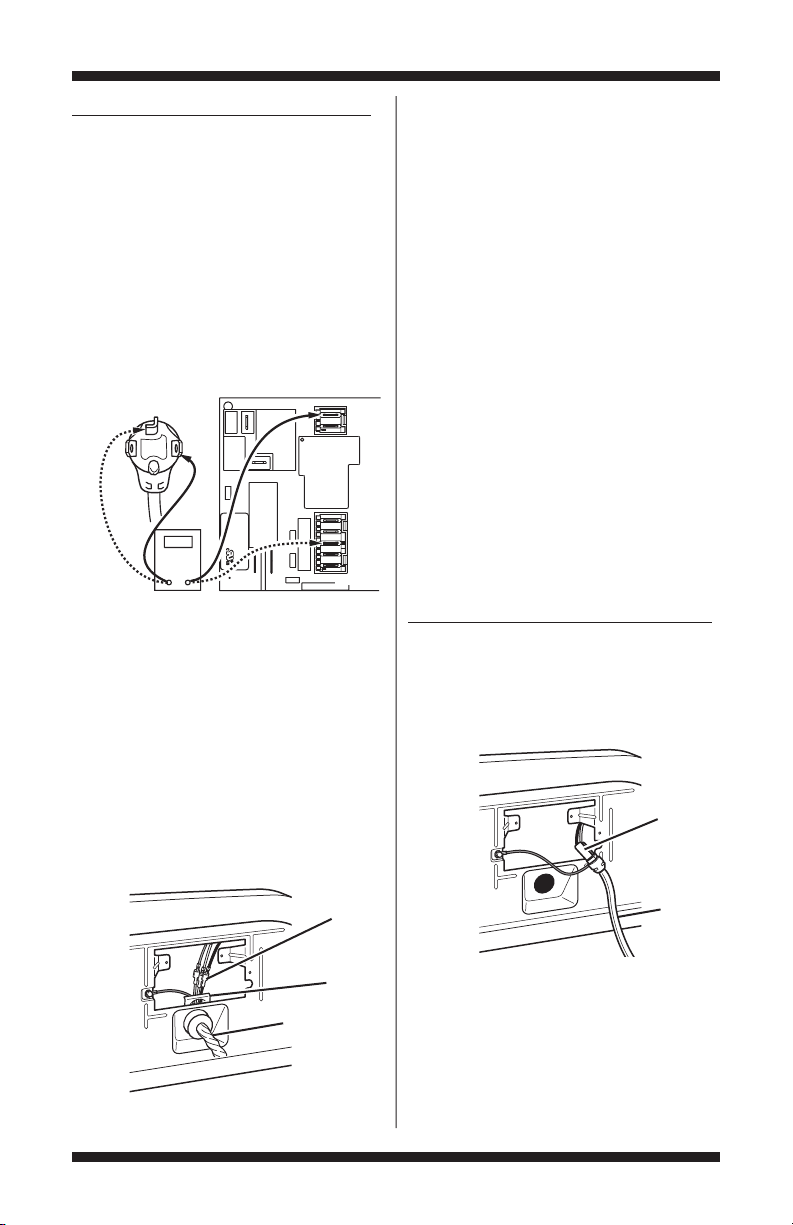
ELECTRIC DRYER (Canadian Installations):
1. Unplug dryer or disconnectpower.
2. Remove the cover plate from the backofthe
console panelonthedryer.Seefigure2,page14.
3. Access the machine control electronics
without disconnecting any wiringto the control
board.See Accessing & Removing the Electronic
Assemblies,page 23.
4. With an ohmmeter, check thecontinuity from
L1andN plugterminalsof the power cordto the
terminalsforL1andN onthemachinecontrol
electronics.Seefigure 3b.
Power Cord
Plug
Machine Control
Electronics
Figure 3b. Plug-to-terminal connections
for electric dryer.
If continuity exists for both connections,
go to step 6.
Ifan open circuit is found,checktheintegrity of
theconnectionsof the power cord to the harness
in the dryer; harnessto the machine control board;
andthe integrity of the power cord itself.
5. If it is necessary to replace the power cord,
remove the retaining clip that secures the cord
to the back panel. See figure 4. Disconnect the
cordfrom themain harness and the ground wire
fromthe rearpanel,thenpull outthe powercord.
6. Visually checkthatthe P5 connector is inserted
alltheway into the machine control electronics.
7. Visually checkthatthe user interface assembly
is properly inserted intothe console.
8. If both visual checks pass,replace
the user interface assembly.
9. Reassemble all parts and panels.
10. Plugin dryer or reconnect power.
11. Activate the Service Diagnostic mode per
procedure on page 2. Then activate the User
Interface/Control System test and verify the repair
by completing the Buttons and Indicators testper
procedures on page5.
12. If indicators still do not light, the machine
control electronics has failed:
Unplug dryer or disconnect power.
Replace the machine control electronics.
Reassemble all parts and panels.
Plugin dryer or reconnect power.
Activatethe Service Diagnostic mode per
procedure on page 2. Then activate the User
Interface/Control System test and verify the repair
by completing the Buttons and Indicators testper
procedures on page5.
GAS DRYER (U.S.and CanadianInstallations):
1. Unplug dryer or disconnectpower.
2. Remove the cover platefromtheback of the
console panel on the dryer. See figure 2, page14.
3. Checkthat the power cordis firmly connected
to the dryer’s wireharness.See figure 5.
Wire
Harness
Wire
Harness
Retaining
Clip
Power Cord
Figure 4. Remove the retaining clip.
PAGE 15
Figure 5. Power cord-to-wire harness
connection for gas dryer.
4. Access the machine control electronics
without disconnecting any wiringto the control
board.See figure 12,page 23.
5. With an ohmmeter, check for continuity
between the neutral (N) terminal of the plug and
P8-3(white wire)on the machine control board.
Power
Cord
FOR SERVICE TECHNICIAN ONLY - DO NOT REMOVE OR DESTROY
COM
Neu
G
L1
L1
Masse
N
Neu
N
G
Masse
The left-hand side of figure 6 shows the position
of the neutral terminal (N) on the powercord plug.
Alsosee figure 13,page 24.
If there is continuity, go to step 6.
If there is no continuity, disconnect the white
wireof the harness from the power cord at the
locationillustrated in figure 5, page 15.Test the
continuity of the power cord neutral wireas
illustrated in figure 6. If an opencircuit is found,
replace the power cord.Otherwise, go to step 6.
Power Cord Plug
Figure 6. Power cord terminals, gas dryer.
6. In a similar way, check the continuity between
the L1 terminal of the plug and P9-2 (black wire)
on the control board.
If there is continuity, go to step 8.
If there is no continuity, check the continuity of
the power cord in a similar way to that illustrated
in figure 6,but for power cord’s L1wire.
If an open circuit is found, replace the power
cord. Otherwise,go to step 7.
7. Replacethemainharness.
8. Visually checkthatthe P5 connector is inserted
all the way intothe machine control electronics.
9. Visually check that the user interface
assembly is properly inserted into theconsole.
10. If bothvisual checks pass,replace the
userinterfaceassembly.
11. Reassemble all parts andpanels.
12. Plugin dryer or reconnect power.
13. Activate the Service Diagnostic mode per
procedure on page 2. Then activate the User
Interface/Control System test and verify the repair
by completing the Buttons and Indicators testper
procedures on page5.
14. If indicators still do not light, the machine
control electronics has failed:
Unplug dryer or disconnect power.
Replace the machine control electronics.
Reassemble all parts and panels.
Plugin dryer or reconnect power.
Activatethe Service Diagnostic mode per
procedure on page 2. Then activate the User
Interface/Control System test and verify the repair
by completing the Buttons and Indicators testper
procedures on page5.
TEST #2 Motor Circuit
This test will checkthe wiring to the motor and
the motor itself.The followingitems are part of
thismotorsystem:
Part of Motor System Dryer Dryer
Harness/connection ✔✔
Thermal fuse ✔ no
Belt/belt switch ✔✔
Drive motor ✔✔
Centrifugal switch ✔✔
Doorswitch ✔✔
Machine control ✔✔
electronics. See ESD
information,page 1.
1. Unplug dryer or disconnectpower.
2. Access the machine control electronics and
measure the resistance across P8-4 and P9-1.
SeeAccessing & Removing the Electronic
Assemblies,page 23.
If resistance across P8-4 and P9-1is in the
range of 1 to 6 Ω, replace the machine control
electronics.
Otherwise,go to step 3.
3. Checkthe wiring and components in thepath
between these measurementpointsby referring
to the appropriatewiring diagram (gas or electric),
pages 25–32.
ELECTRIC DRYER ONLY:
fuse. See TEST#3b,page 20.
ALL DRYERS:
Continue with step 4 below to test
the remaining components in the motorcircuit.
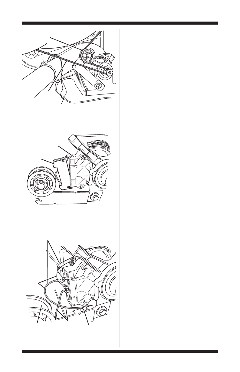
4. Checkthe belt switch and drivemotor. Access
the belt switch and drive motor by removing the
backpanelscrews(to loosen front panel/drum
assembly).Slowlyremove the drum belt fromthe
spring-loaded belt switchpulley, gently letting the
beltswitch pulley down.See figure 7,page 17.
PAGE 16
Electric Gas
Check the thermal
1
5
3
46
2
FOR SERVICE TECHNICIAN ONLY - DO NOT REMOVE OR DESTROY
1
5
3
4
6
2
Belt Switch Pulley
Drum
Belt
Figure 7. Slowly remove drum belt.
5. Remove the white connectorfrom the drive
motor switch. See figure 8.
Drive Motor
Switch
White
Connector
Figure 8. Remove white connector.
Main Winding:
Lt. Blue Wire in Back
and Bare Copper Wire
Start
Winding:
Lt. Blue
Wire in
Back
and Bare
Copper
Wire
Belt Switch
Pulley
Figure 9. Main and start winding measure points
andchecking the belt switch.
Lt. Blue
Wires
Belt Switch
6. Usingfigure9, check for the resistancevalues
of the motor’s Main and Start winding coils as
shown in the following table:
NOTE: Main and Start winding coils must be
checked at the motor.
Resistance Contact Points
Winding Ω of Measurement
3.0–4.0 back at pin 4 and
MAIN (2.5–3.0 bare copper wire
on Maytag) on pin5 of black
drive motorswitch
2.4–3.4 back at pin 4 and
START (2.0–2.5 bare copperwire
on Maytag) on pin3 of black
drive motorswitch
If the resistance at the motor is correct,there
is an open circuit between the motor and machine
control electronics. Checkfor failed belt switch.
If the Start windingis in question andthe
resistance is much greater than 4 Ω,replace
the motor.
7. Check the belt switch by measuring resistance
between the twolight bluewires,as shown in
figure9, while pushing up thebelt switch pulley.
If the resistancereading goes from infinity
to a few ohms as pulley arm closes the switch,
beltswitch is OK. If not, replace the beltswitch.
If belt switchis OK and there is stillan open
circuit, check and repair the wiringharness.
8. DoorSwitch problems can be uncovered by
following procedureunder DiagnosticTest:Door
Switch, page 5; however, if this was not done,
thefollowing can be done without applying power
to the dryer. Connectan ohmmeter across P8-3
(neutral,white wire) andP8-4 (door, tan wire).
With the door properly closed, the ohmmeter
shouldindicatea closed circuit(0–2 Ω).
If not,replace the doorswitch assembly.
TEST #3 Heater
This test is performed when eitherof the
following situations occur:
✔ Dryer doesnot heat
✔ Heat will not shut off
This test checks the componentsmaking up the
heating circuit.The following itemsare part of
thissystem:
PAGE 17
Lt.blue wire in
Lt.blue wire in
FOR SERVICE TECHNICIAN ONLY - DO NOT REMOVE OR DESTROY
Part of Heating System Dryer Dryer
Electric Gas
Harness/connection ✔✔
Heater relay ✔✔
Thermal cut-off ✔✔
Thermal fuse no ✔
Highlimitthermostat ✔✔
Heatelement assembly ✔ no
Gas burnerassembly no ✔
Centrifugal switch ✔✔
Exhaust thermistor ✔✔
Machine control ✔✔
electronics. See ESD
information,page 1.
Userinterfaceand ✔✔
housing assembly
Gas supply no ✔
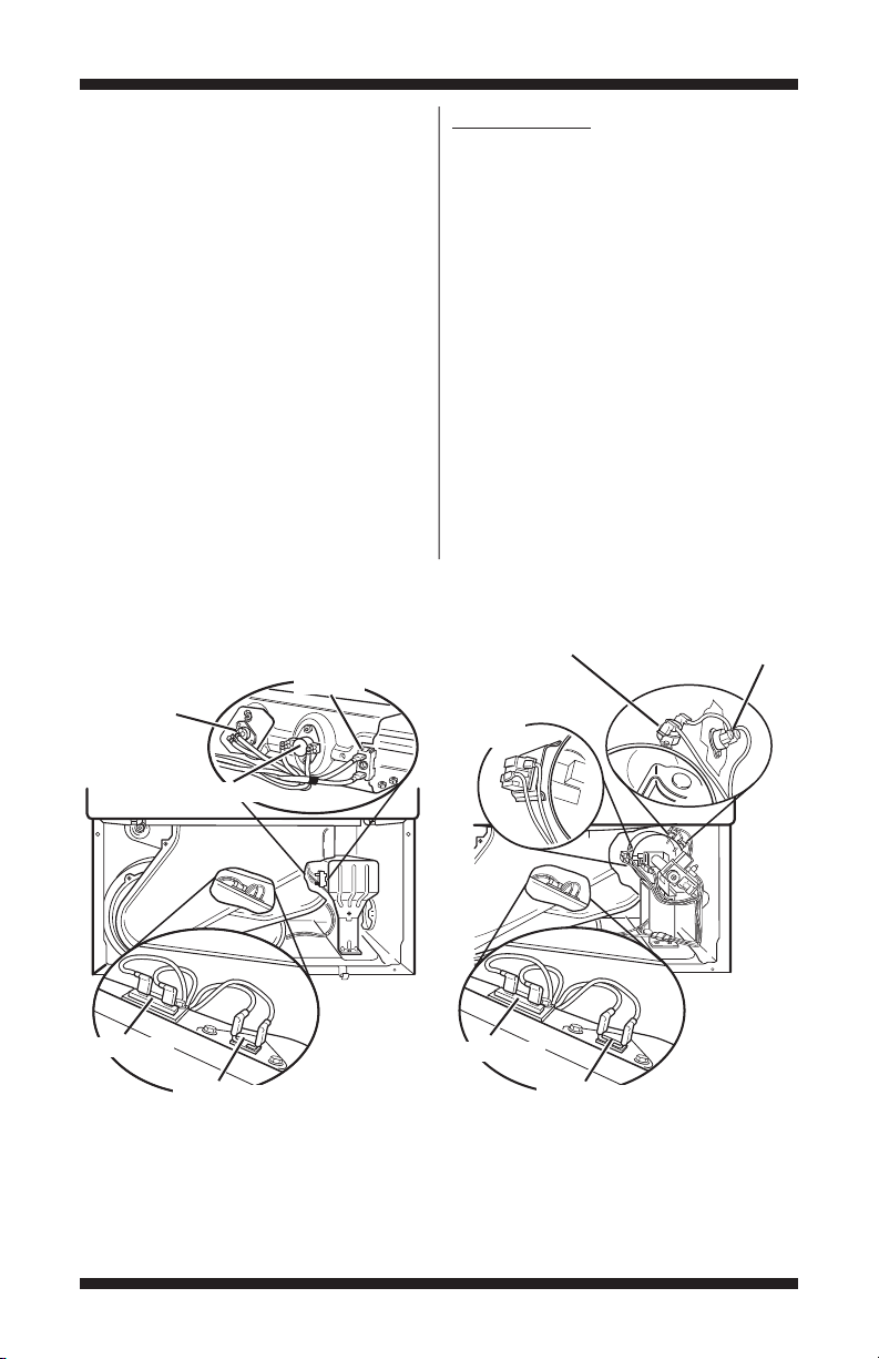
Dryer does not heat:
Locate the components using figure 10.
Heater
Element
Thermal
Cut-Off
ELECTRIC DRYER:
1. Unplug dryer or disconnectpower.
2. Remove the toe panel to access the thermal
components.
3. Usingan ohmmeter and referring to thewiring
diagram,measure the resistance from the red
wireterminal at the thermal cut-off to the red
wireterminal at the heater.
If the resistanceis about 10 Ω, go to step 5.
If an open circuit is detected, go to step4.
4. Visually check the wire connections to the
thermal cut-off, high limit thermostat, and heater.
If connections look good, check for continuity
across each of these components.
Replace the heaterif it is electrically open.
Replace both the thermalcut-off and high limit
thermostat if either oneis electrically open.
High Limit Thermostat
Flame
Sensor
Thermal
Cut-Off
High Limit Thermostat
Thermal Fuse
Exhaust Thermistor
Electric Dryer
Figure 10. Thermal Components, viewed from front.
PAGE 18
Thermal Fuse
Exhaust Thermistor
Gas Dryer

FOR SERVICE TECHNICIAN ONLY - DO NOT REMOVE OR DESTROY
5. If no open circuitis detected, remove the P14
connector, thenmeasure the resistance between
P14-3 (red-white wire) and P14-6(red-white wire)
at theconnector. See figure 13, page 24,for
connector location;andAccessing & Removing
theElectronicAssemblies,page 23.
If 5–15 kΩ are measured,replace the
machine control electronics.
If the resistance is less than 1 kΩ, replace
theexhaust thermistor.
GAS DRYER:
1. Unplug dryer or disconnectpower.
2. Remove the toe panel to access the thermal
components.
3. PerformTEST #3b, page20. If thethermal
fuseis OK, go to step 4.
4. PerformTEST #3c, page20. If thethermal
cut-off is OK, go to step 5.
5. Locatethe highlimit thermostat.See figure
10,page 18. Measure the continuity through it
by connecting the meter probes on the red wire
and blue wireterminals.
If there is an opencircuit,replace the high
limit thermostatand thethermal cut-off.
Otherwise,go to step 6.
6. PerformTEST #3d, page20. If this is OK,
replace the machine control electronics.
Heat will not shut off:
1. Unplug dryer or disconnectpower.
2. Access the machine control electronics.
Remove the P14 connector, then measure the
resistance between P14-3 (red-white wire) and
P14-6 (red-white wire) at the connector. See
figure 13,page 24 for connector location; and
Accessing & Removing theElectronicAssemblies,
page23.
If 5–15 kΩ are measured,replace the
machine control electronics.
If the resistance is greater than 20 kΩ,
replace the exhaust thermistor.
TEST #3a Exhaust Thermistor
The machine control electronics monitors
the exhaust temperature using the exhaust
thermistor,and cycles the heaterrelay on
and off to maintain the desired temperature.
Begin with an empty dryer and a clean
lint screen.
1. Plug in dryer or reconnect power.
2. Start the Timed Dry cycle.
3. If after60 seconds, f3 e1 or f3 e2 flashes
in the display (on models withsevensegment
display) or the WET indicator flashes F3E1 or
F3E2(on models without seven segment display)
and the dryer shuts off, the thermistor or wire
harness is eitheropen or shorted.
Unplugdryeror disconnect power.
Check wire connections at the machine control
electronics andthermistor.SeeAccessing &
Removing theElectronicAssemblies,page 23,and
forthermistor location,see figure 10,page 18.
If wire connections aregood,remove the two
wires fromthethermistorand replacethe thermistor.
Reassembleall parts and panels.
Plug in dryer or reconnect power.
4. If f3 e1 or f3 e2 does not flashin the display
(on modelswith seven segment display) or the
WET indicator does not flash F3E1 or F3E2 (on
models without seven segment display),the
connections to the thermistor are good.Therefore,
check the exhaust temperature value at any or
all of the temperature levels in question, using
theTimed Dry cycle,and the following process:
Holda glass bulb thermometer capable of
reading from 90° to 180°F (32° to 82°C)in the
center of the exhaust outlet.The correct exhaust
temperaturesare as follows:
EXHAUST TEMPERATURES
Temperature HeatTurns Off* Heat Turns On
Setting °F (°C) °F (°C)
High 155°±5° (68°±3°) 10–15°
Medium High150°±5° (66°±3°) (6–8°)
Medium 140°±5° (60°±3°) below
Low 125°±5° (52°±3°) the
Extra Low heat
(Whlpl& Mytg)115°±5° (46°±3°) turn off
(Kenmore) 105°±5° (41°±3°) temperature
* The measured overshoot using the glassbulb
thermometer in the exhaust outlet can be 30°F
(17°C) higher.
5. If the exhaust temperatureis not within
specified limits,unplug dryer or disconnect
power. Remove the P14 connector, then measure
the resistancebetween P14-3 (red-white wire)
and P14-6 (red-white wire) at the connector. See
figure 13,page 24 for connector location; and
Accessing & Removing theElectronicAssemblies,
page23.
NOTE: Allthermistorresistance measurements
mustbe made while dryeris unpluggedor
disconnected from power.
PAGE 19
FOR SERVICE TECHNICIAN ONLY - DO NOT REMOVE OR DESTROY
The following tablegivestemperatures and their
associated resistance values.
EXHAUST THERMISTOR RESISTANCE
Temp Range Temp Range
°F (°C) kΩ °F (°C) kΩ
50° (10°) 19.0–22.0 80° (27°) 8.5–10.5
60° (16°) 14.8–16.8 90° (32°) 6.8–8.8
70° (21°) 11.5–13.5 100° (38°) 5.0–7.0
If the thermistor resistance does not agree
with table,replace the exhaustthermistor.
If the thermistor resistance checks agree
with the measurementsin the table, replace
themachine control electronics.
Res. Res.
TEST #3b Thermal Fuse
ELECTRIC DRYER: The thermal fuseis wired
in series with the dryerdrive motor.
GAS DRYER:
withthe dryergas valve.
ALL DRYERS:
1. Unplug dryer or disconnectpower.
2. Access the thermal fuse by first removing
the toe panel. Forthermal fuse location,see
figure 10,page 18.
3. Usingan ohmmeter,check the continuity
acrossthethermalfuse.See figure 10 for location.
If the ohmmeter indicates an open circuit,
replace the failedthermal fuse.
The thermal fuse is wired in series
TEST #3c Thermal Cut-Off
If the dryer doesnot produce heat, check the
status of the thermal cut-off.
1. Unplug dryer or disconnectpower.
2. Access the thermal cut-offby firstremoving
the toe panel.
3. Usingan ohmmeter,check the continuity
across the thermal cut-off.See figure 10,page
18,for location.
If the ohmmeter indicates an open circuit,
replace the failedthermal cut-off andhighlimit
thermostat. In addition, check forblocked or
improper exhaust system,or failed heat element
(electric dryer).
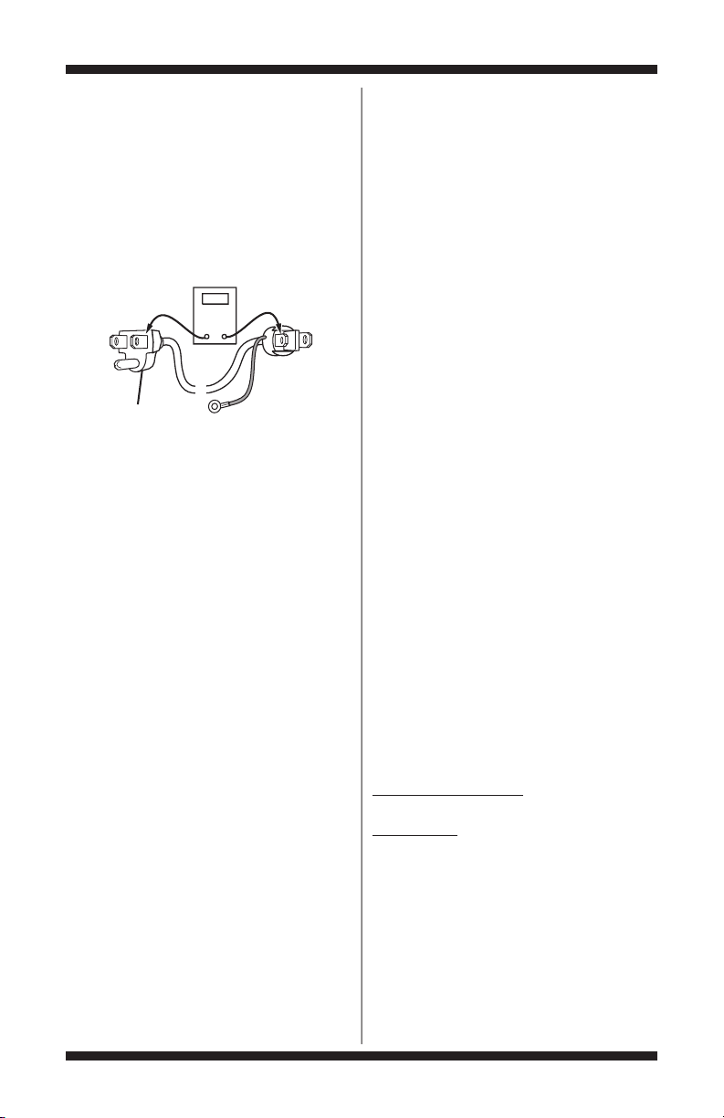
TEST #3d Gas Valve, Gas Dryer Only
1. Unplugdryer or disconnect power.
2. Accessthe gas valve by removingthe
toe panel.
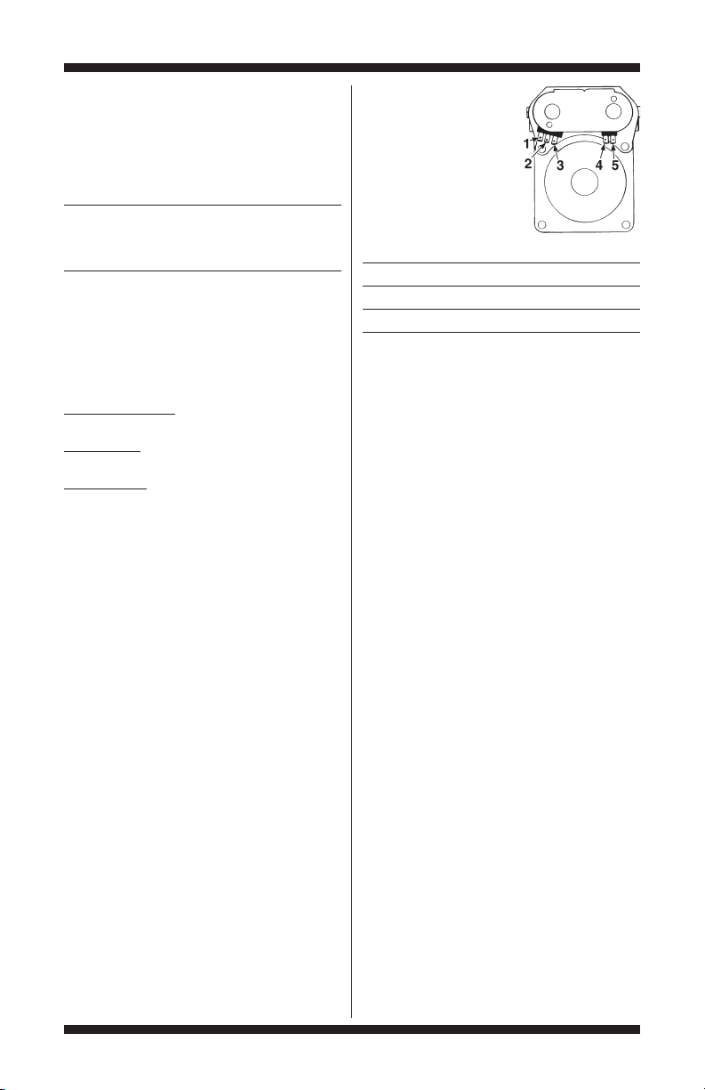
3. Use an ohmmeter to
determine if a gas valve
coilhas failed.Remove
harness plugs.Measure
resistance across terminals.
Readings should match
those shownin the
following chart. If not,
replace coil.
Terminals Resistance (Ω)
1 to 2 1365 ± 25
1 to 3 560 ± 25
4 to 5 1220 ± 50
IMPORTANT: Be sure all harness wiresare
looped back through the strain relief after
checking or replacing coils.
TEST #4 Moisture Sensor
NOTE: This test is started with the dryer
completely assembled.
This test is performed when an automatic cycle
stopstoo soon,or runsmuchlonger thanexpected.
NOTE: Dryer will shut down automatically
after 2-1/2hours.
The following items are part of this system:
Harness/connection
Metal sensor strips
Machine control electronics.
See ESD information,page 1.
1. Enter ServiceDiagnosticmode and selectthe
UserInterface/ControlSystemtest.See procedure
on page5.
2. Open the dryer door. Thedryer should
beepand an alphanumericnumber should be
displayed (on models with sevensegment
display) or the TEMP, TEMP LEVEL, or DRYTEMP
indicators should change (on modelswithout
seven segment display).
3. Locatethe two metal sensor strips on the
faceof the lintscreenhousing.Bridge thesestrips
witha wet cloth or finger.
If a beep tone is heard andan alphanumeric
numberis displayed on theconsole (on models
with seven segmentdisplay)or theTEMP,TEMP
LEVEL,or DRY TEMP and STATUSindicators change
(onmodels withoutseven segmentdisplay), the
sensorpassed the test.Go to step 9.
If a beep tone is notheard, or a continuous
beep toneis heard before bridging the moisture
strips, continue with step4.
PAGE 20
 Loading...