

Whirlpool BSZ 4007 IN, BSN 4006 IN, BSZ 4007 SW User manual
53862-gb.fm5 Page 39 Monday, March 19, 2001 10:25 AM
TABLE OF CONTENTS GB
INSTALLATION
ELECTRICAL CONNECTION
BEFORE USING THE OVEN
PROTECTING THE ENVIRONMENT
PRECAUTIONS AND GENERAL
RECOMMENDATIONS
OVEN ACCESSORIES
COOKING CHART
CLEANING THE OVEN AND ITS ACCESSORIES
TROUBLESHOOTING GUIDE
PAGE
PAGE
PAGE
PAGE
PAGE
PAGE
PAGE
PAGE
PAGE
40
41
42
42
42
43
44
45
46
AFTER-SALES SERVICE
DECLARATION OF CONFORMITY CE
PAGE
PAGE
47
47
39
53862-gb.fm5 Page 40 Monday, March 19, 2001 10:25 AM
INSTALLATION
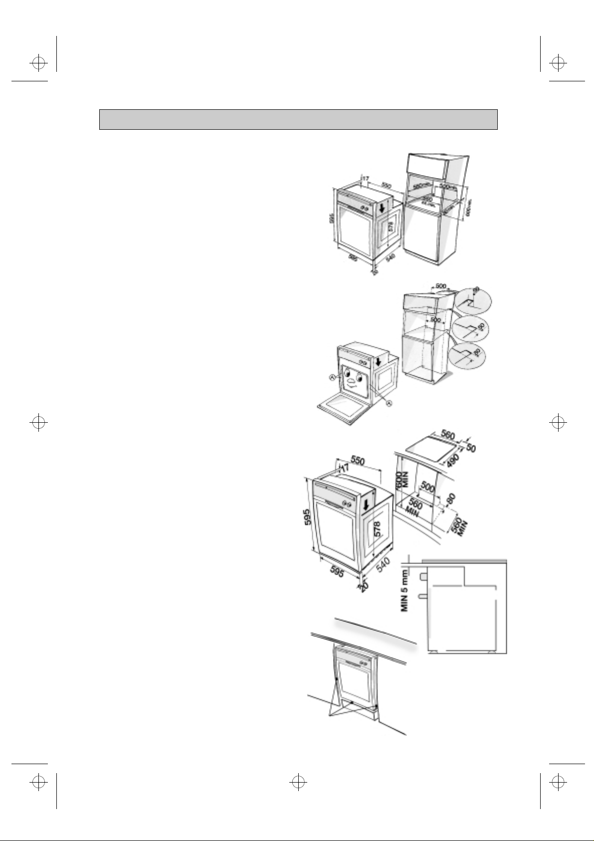
Technical information for the installer
•
After removing the oven from its packaging,
before making the connections place it on the
polystyrene foam base to protect it from
damage.
•
Do not attempt to lift the oven by the handle.
Lift at the sides as shown in the figure
(see arrow).
•
Check that the appliance has not been
damaged in transit.
•
Oven dimensions and kitchen unit
dimensions are shown in the opposite figure.
•
Kitchen units in contact with the oven must
be heat resistant (80° C min).
•
Install the oven in the housing, lifting it at the
sides, taking care not to trap the wires of the
electrical supply cable.
•
For correct ventilation, follow the ventilation
opening directions shown in the figure
(500 min x 80 mm and 500 min x 50 mm
inside the cabinet).
•
Secure the oven to the kitchen unit with
screws (A) as shown.
•
The oven has also been designed for
building-in under a cooktop.
NOTE:
To allow for proper ventilation, we
recommend that you left an opening of at least
500 x 80 mm or an equivalent area in the lower
section of the housing.
An additional opening of 5 mm is required
between the oven top rim and the cooktop lower
rim: this opening must not be closed by strips or
housing crosspieces.
During oven installation, care must be taken to
ensure that the sides are not touching the front
edges of the housing or adjacent drawers and
doors (see picture).
40
No contacts
53862-gb.fm5 Page 41 Monday, March 19, 2001 10:25 AM
ELECTRICAL CONNECTION
• Warning: Do not connect to the power
supply before you have finished
connecting the oven.
• Make sure the oven is installed and
connected to the electricity supply by a
qualified technician in accordance with
the manufacturer’s instructions and in
compliance with local regulations.
• The installer is responsible for the correct
electrical connection of the oven and the
observance of the relative safety
regulations.
• The oven must be connected to the
electricity supply by means of an all-pole
disconnect switch with minimum contact
gap of 3 mm.
• The oven must be earthed by law.
• Do not use multiple plug adapters or
extension leads.
• After the oven has been installed, the
electrical components must be
inaccessible.
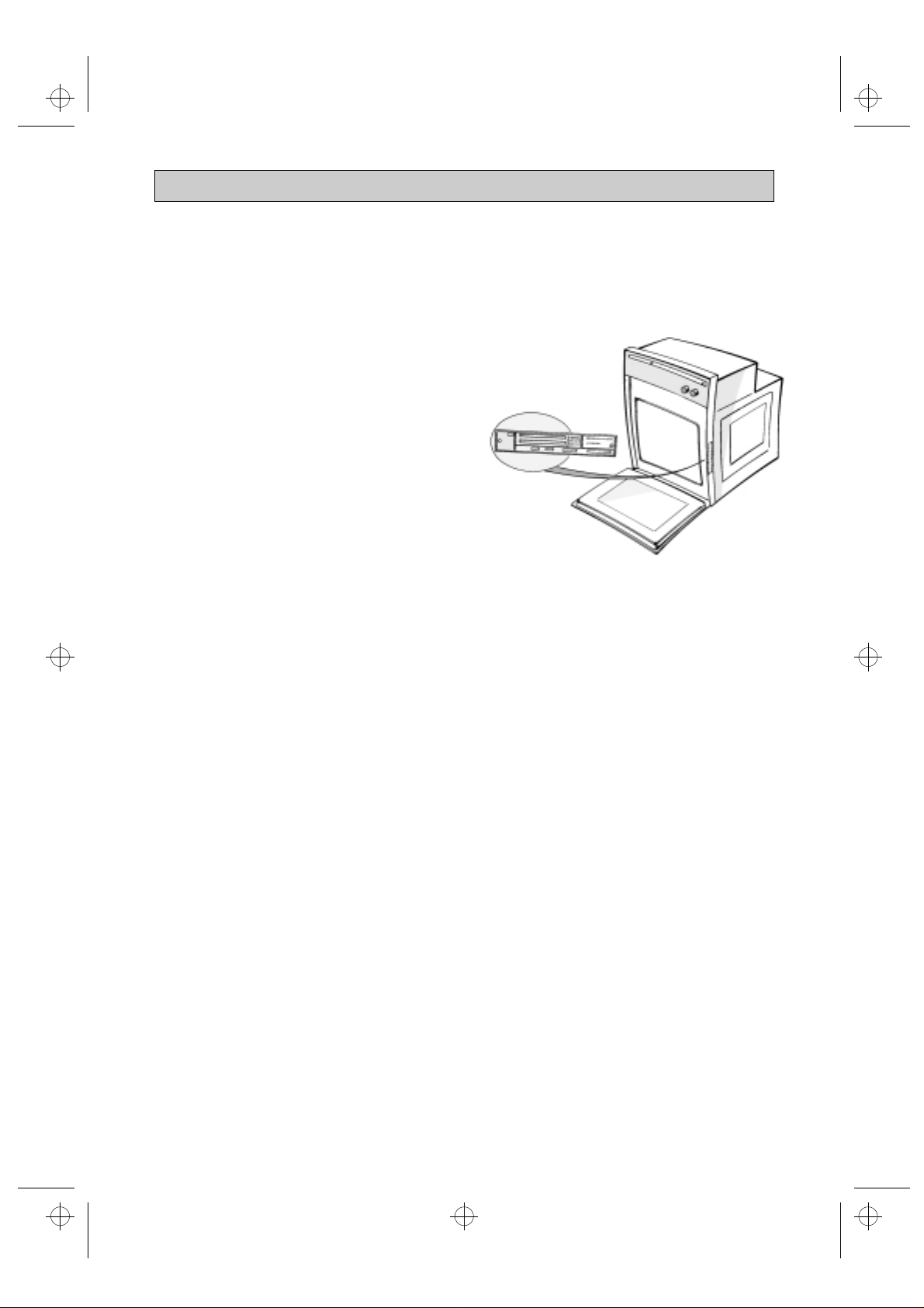
• Make sure that the voltage shown on the
rating plate is the same as the power
supply voltage in your home. The rating
plate is on the front edge of the oven
cavity (visible with oven door open).
41
 Loading...