


SERVICE
Model AVM 215 BL
Version 8538 215 12491 Page
Whirlpool Europe
Customer Services
AVM 215 BL
Service-Manual
Microwave oven
AVM 215 BL
Introduction safety 2
Technical data 3
Text/Legend 4
Spare part list 9
Exploded view 10
Circuit diagram 11
Wiring diagram 12
This documentation is only intended for qualified technicians who are aware of the respective safety regulations.
Date: 10.05.1995 Subject to modification
Document-No.: 4812 714 10519

10.05.1995 / Page 2 Whirlpool Europe
Doc. No: 4812 714 10519 Customer Service
SERVICE
Introduction safety
INTRODUCTION
Before leaving the factory each oven is carefully checked.
It must however, be installed and used correctly.
Despite all the steps taken to make the oven safe, the safety is dependent on the correct installation and the fact
the user understands how to use and maintain the oven.
The information in this section should be used as a reminder that the oven is safe and that anyone who uses it must
first read the instructions for use in order to be able to use the oven correctly and obtain best results.
SAFETY
To avoid injury to yourself and damage to the appliance always work to the following rules when servicing an oven.
Always disconnect the plug from the mains before starting work.
If there is no plug switch off the electric supply at the control box.
When you have finished servicing an oven before you reconnect it to the mains, make sure that:
- all the internal connections are correct
- the wires are insulated and not touching the door or the cabinet or anything sharp
- all the earth connections are electrically and mechanically sound
- do not modify or anyway interfere with the safety devices built-in to the oven
- make sure that each replacement part you use conforms to the manufacturer´s specifications
Do not start a repair if you have any doubt as to your ability to complete it.
CAUTION - MICROWAVE RADIATION
PERSONNEL SHOULD NOT BE EXPOSED TO THE MICROWAVE ENERGY WHICH MAY RADIATE FROM THE MAGNETRON,
WAVEGUIDE OR ANTENNA IF THEY ARE IMPROPERLY USED OR CONNECTED. ALL INPUT
AND OUTPUT MICROWAVE CONNECTIONS, WAVEGUIDES, FLANGES AND GASKETS MUST BE SECURE.
NEVER OPERATE THE DEVICE WITHOUT A MICROWAVE ENERGY ABSORBING LOAD ATTACHED.
NEVER LOOK INTO AN OPEN WAVEGUIDE OR ANTENNA WHILE THE DEVICE IS ENERGIZED.
NEVER OPERATE AN OVEN WITH CABINET OFF WITHOUT MEASURING THE MICROWAVE LEAKAGE
AROUND MAGNETRON AND VISIBLE MICROWAVE CONNECTIONS (WELDING JOINTS).
Do not operate the oven if the following conditions exist:
- the door does not close firmly against the door support because of the door being warped or the hinges damaged.
- The door trims or seals are damaged.
- If there is any visible damage to the oven.
- if the door does not close properly.
Avoid operating the oven if known components in the interlock system, oven door or microwave
generating assembly are known defective. They must be replaced.
WARNING - HIGH VOLTAGE
IT IS POSSIBLE TO COME IN CONTACT WITH LETHAL HIGH VOLTAGE WHEN WORKING WITH
HV TRANSFORMER, HV CAPACITOR AND MAGNETRON. THEREFORE NEVER TRY TO MEASURE
THE HIGH VOLTAGE. ALWAYS TAKE UTMOST CARE WHEN PERFORMING ELECTRIC
MEASUREMENTS INSIDE THE OVEN.

SERVICE
Technical data
Whirlpool Europe 10.05.1995 / Page 3
Customer Service Doc. No: 4812 714 10519
Dimensions of cabinet
Height 330 mm
Width 553 mm
Depth 477 mm
Dimensions of cavity
Height 227 mm
Width 372 mm
Depth 395 mm
Cavity volume 34 l
Turntable diameter 360 mm
Weight
Net 23 Kg
Packed 26 Kg
Power
Output power 950 +/- 60 W
Microwave frequency 2450 MHz
Grill
Quarzgrill 1200 W
Timer
Digital 90 min
Accessories
Grill grid, Spacer, Crisp plate
Electrical
Voltage 220-240 V
Frequency 50 Hz
Power consumption 2850 W
Power consump. CH/DK 2300 W
Power consump. 12,6 A
Power consump.CH/DK 10 A
Fuse Eu 16 A
Fuse CH/DK 10 A
UK 13 A
10.05.1995 / Page 4 Whirlpool Europe
Doc. No: 4812 714 10519 Customer Service
Text/Legend
Functional Description
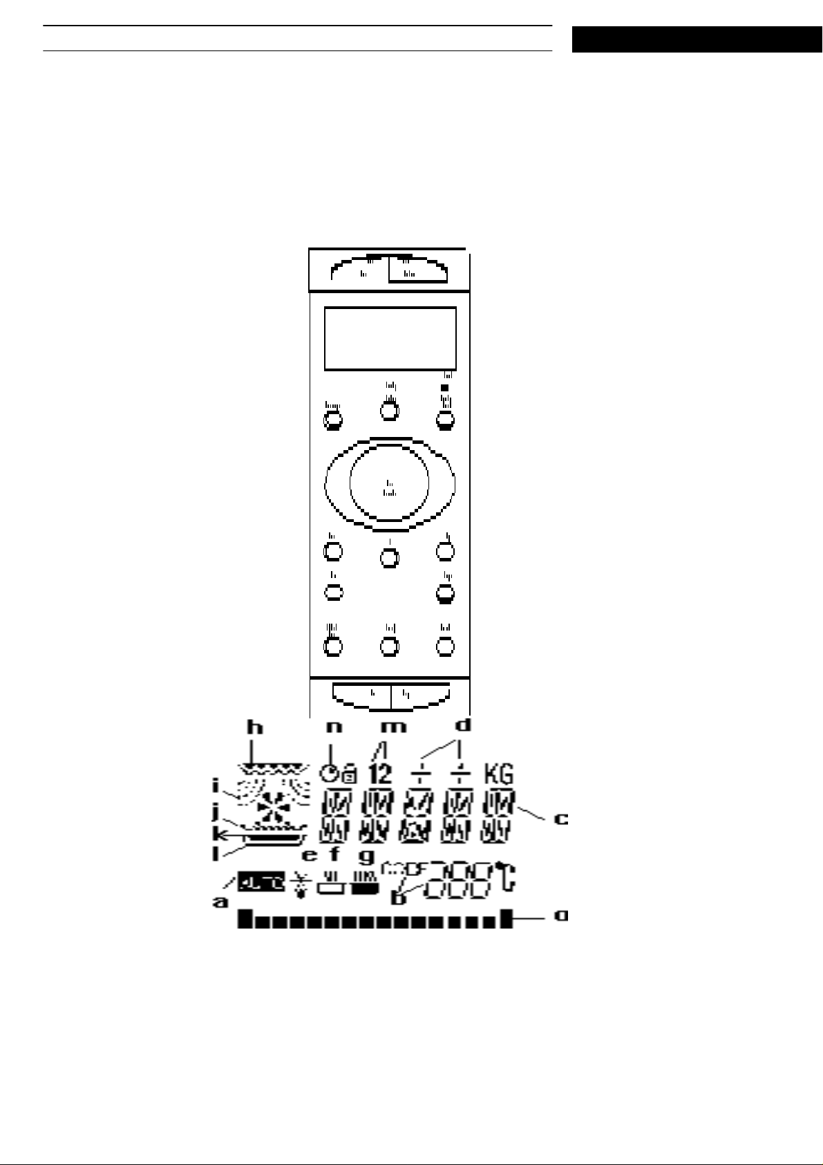
Control panel layout
SERVICE

Whirlpool Europe 10.05.1995 / Page 5
SERVICE
Customer Service Doc. No: 4812 714 10519
Display symbols description
a) "AUTO" is lit when auto defrost, auto reheat, beverage or auto crisp is selected.
b) "CODE", together with a number, is lit when auto crisp reheat or auto crisp cook is selected. The number
indicates food class.
c) "SENSE" is displayed when an auto function is started.
d) Personal preference for the auto functions is indicated by "--", "-","+", "++". When no personal preference is
choosen, all are turned off.
e) The defrost symbol is lit during manual or auto defrost.
f) The reheat symbol is lit when Auto Reheat or Auto Crisp Reheat is selected.
g) The cook symbol is lit when Auto Crisp Cook is selected.
h) The grill symbol is lit when a function using the grill element is selected. The lower part of the symbol
blinks during cooking.
i) The MW symbols are lit when a function using microwaves is selected.
j) The defrost grid symbol is lit when Auto Defrost is selected, indicating that the defrost grid must be used.
k) The pan symbol is lit when a crisp function is selected, indicating that the crisp pan must be used.
l) The plate symbol is lit when a cooking function is selected, indicating that the turn table must be used.
m)The stage indicators are lit during stage cooking.
n The timer symbol is lit when the independent timer is displayed. It blinks when the timer operates in the
background.
o) The process/power bar indicates how far the process has advanced when using the auto functions.
1000W MW is indicated by a rolling bar.
Calibration
Before the oven can be operated, a calibration must be performed. To start a calibration, make sure that
a cross and a glass turn-table are mounted in the oven. A weight of 200 g must be placed on the centre
of the turn-table. Enter test mode and press START. The cavity light will go on, the turn-table will start
rotating and "CAL" will be displayed. After approximately 30 seconds a number will be displayed. This is
the calibration factor.Checkthat the number is within specified limits. Press START to store the factor. If
STORE is displayed, the factor has been stored successfully. Otherwise "ERR 8" will be displayed
Calibration factors should be between 170 - 194.
Real time clock
Time is set by pressing the CLOCK button. Set the hours with the timer knob. Press the CLOCK button
again and set the minutes with the timer knob. Finally, press the CLOCK button again to clear the sec-
onds and start the clock.
Cooking time
The cooking time is set with the timer knob. The maximum cooking time that can be set is 99 minutes.
Microwave power
To adjust the microwave power, press the POWER button. The current power level is displayed in Watts
for 2 seconds. The power level is stepped with the POWERbutton, while the power level is displayed. If
POWER is pressed when the oven is in stand by, the power level is set to 750 W. The oven is st arted
with the START button.

10.05.1995 / Page 6 Whirlpool Europe
Doc. No: 4812 714 10519 Customer Service
JET
If the oven is in stand by and the START button is pressed, cooking is started immediately at full power.
If the oven is already cooking, the timer is incremented 30 seconds each time the button is pressed, but
the power setting is not affected.
Auto Defrost
Press the AUTO DEFROST button. Adjust doneness during the first 20 seconds with the timer knob.
After a while the display shows the estimated defrost time, which is decreased during operation. The
process bar indicates how far the process has advanced.
Auto Reheat
Press the AUTO REHEAT button. Adjust doneness during the first 20 seconds with the timer knob. After
a while the display shows the estimated reheat time, which is decreased during operation. The process
bar indicates how far the process has advanced.
SERVICE
Beverage
Press the BEVERAGE button. Adjust doneness during the first 20 seconds with the timer knob. After a
while the display shows the estimated reheat time, which is decreased during operation. The process
bar indicates how far the process has advanced.
Auto Crisp Reheat
Press the AUTO CRISP REHEAT button. Select food class by repeatedly pressing this button. Adjust
doneness with the timer knob. Start by pressing the START button After a while the display shows the
estimated reheat time, which is decreased during operation. The process bar indicates how far the process has advanced.
1 - Auto Crisp Reheat Potato Products
2 - Auto Crisp Reheat Pizza
3 - Auto Crisp Reheat Pie/Quiche
4 - Auto Crisp Reheat Chicken Parts
5 - Auto Crisp Reheat Refresh Bread
Auto Crisp Cook
Crisp
Press the AUTO CRISP COOK button. Select food class by repeatedly pressing this button. Adjust doneness with the timer knob. Start by pressing the START button After a while the display shows the estimated reheat time, which is decreased during operation. The process bar indicates how far the process
has advanced.
1 - Auto Crisp Cook Pizza
2 - Auto Crisp Cook Chicken Parts
Select crisp by pressing the CRISP button. Set the cooking time with timer knob and start with the
START button.

SERVICE
Grill
Use the GRILL button to select grill operation. Set the cooking time with timer knob and start with the
START button.
NOTE: - When the Crisp or Grill function is selected, grill indicator 1 is lit. When cooking is started, grill
Timer
The TIMER button starts the independent timer. The timer is initiated to 5 s, the timer symbol is dis-
played (not blinking). Display of the timer is toggled with the same button. (If the timer has been started
there is a display time out of 3 s). The timer is set with the timer knob and started with the START but-
ton. 3 seconds after the timer has been started, the function that was already activated is displayed, and
the timer symbol blinks. If the oven is in stand-by, the timer display continues (without blink). The possi-
ble time that can be set ranges from5sto9hours and 59 minutes. Eight fast beeps indicates that the
timer has counted down to zero. If the timer has been started, it can be turned off by turning the time to
zero, or by pressing the STOP button when the timer is displayed.
Whirlpool Europe 10.05.1995 / Page 7
Customer Service Doc. No: 4812 714 10519
indicator 2 blinks.
Stage
Two stages may be stored. The following functions are excluded:
- the Independent Timer
- Auto Defrost
- Auto Reheat
- Beverage
- Auto Defrost-Reheat
- Auto Crisp Reheat
- Auto Crisp Cook
Stage is used according to the following (starting from stand by):
a) Press STAGE. The "1" symbol is displayed. Initiate MW 750W, 5s.
b) Select function (if other than MW), power, time etc. for stage 1. (Grill selects grill mode, not combina-
tion)
c) Press STAGE. The setting above is stored in stage 1. The "2" symbol is displayed. Initiate MW 750W,
0s (shows clearly that a new stage is displayed).
d) Select function etc. for stage 2.
e) Press STAGE. Stage 2 is stored, and stage 1 is displayed. The "1" symbol is displayed. START may be
pressed directly instead.
Memories
Programming:
Select function, time, power etc. to be stored. Then press a memory button (2 s) until storage is confirmed by a beep. The timer may be stored if it has not been startedand no other function is active in the
background (stand-by).

10.05.1995 / Page 8 Whirlpool Europe
Doc. No: 4812 714 10519 Customer Service
Fetch from memory:
Press the desired memory button, and release it within 2 s. (If the oven is in stand by, the memory contents are displayed immediately when the button is pressed).
When the oven is in operation the memories are not available.
There are no limitations when storing auto functions.
Add a little bit more
The aim of this function is to "add a little bit more" at the end of, or after, a cooking session. Every time a
new cooking sessions started, the time for the process is being measured. (Changing between MW,
combination and grill does not reset this timer). A certain part of the measured time is added to the
remaining running time when ADD is pressed. The "Add" time is kept for 1 minute after the oven has
entered stand by. If ADD is pressed within this time, the "add" time and the function and power that was
last used is recalled. (For the auto functions, the corresponding manual function is used.). The minimum
add time is always 5 seconds, except for crisp, where it is 30 seconds (due to heating of the crisp plate).
SERVICE
Stop
The STOP button aborts any operation started, and returns the oven to stand-by.

Whirlpool Europe 10.05.1995 / Page 9
SERVICE
Customer Service Doc. No: 4812 714 10519
Spare part list
Model AVM 215 BL
Service No. 853821512491
Version 853821512491
Pos. No. 12NC Code Description
002 0 4819 442 38007 Cabinet BL
002 2 4819 462 79721 Cover upper
002 2 4819 462 79722 Cover lower
013 0 4819 462 79423 Foot
041 0 4819 417 19384 Hinge upper
041 1 4819 417 19379 Hinge,lower
100 0 4819 442 38245 Door cpl. BL
110 0 4819 498 69967 Grip WH
120 0 4819 442 38004 Door,inner
121 0 4819 459 48662 Frame,breaker inner
130 0 4819 276 38338 Unit,pushbutton
130 1 4819 466 89172 Clip
131 0 4819 535 98529 Door latch
141 0 4819 450 69884 Oven glass BL
143 0 4819 459 48664 Frame,breaker BL
234 0 4819 325 18056 Plate,protect.
244 0 4819 466 98789 Stand plastic
244 1 4819 458 58562 Grid defrost
245 0 4819 458 19981 Grid
246 0 4819 418 38353 Crisp plate
246 1 4819 498 69875 Grip crispplate
255 0 4819 466 78348 Turntable glass
264 0 4819 520 18029 Ring,set
264 1 4819 462 38767 Rail
301 0 4819 462 38751 Frame pushbuttons
Pos. No. 12NC Code Description
421 0 4819 121 18162 Filter,mains
426 0 4819 218 38039 Diode HV
442 0 4819 361 18361 Motor Blower
442 1 4819 462 58145 Cover fan
442 2 4819 462 58146 Container fan
442 3 4819 466 98922 Casing
443 0 4819 515 28224 Fan wheel
452 0 4819 259 98385 Heating element quarz
452 1 4819 404 78841 Holder quarz tube
452 2 4819 458 58522 Reflector quartz tube
452 3 4819 418 79082 Cover bar
452 4 4819 532 58263 Washer
452 5 4819 532 58262 Washer ceramic
452 6 4819 458 58527 Air guide grill
485 0 4819 321 18253 Cable,HT
490 0 4819 321 18231 Cable,mains cpl. with clamp
502 0 4819 214 78481 Control unit
502 1 4819 209 88046 Microprocessor
502 2 4819 113 88001 Resistor 100 Ohm
502 3 4819 101 48142 Potentiometer
502 4 4819 130 98002 Coupler,photo not shown
561 0 4819 282 48247 Thermostat magnetron 145 C
562 0 4819 282 48277 Thermostat 160C
564 0 4819 282 48275 Thermostat 165C
615 0 4819 280 68319 Relay
301 1 4819 276 38329 Unit,pushbutton BL
305 0 4819 404 78937 Holder
320 0 4819 453 49998 Control panel BL
332 0 4819 413 98011 Button,push
334 0 4819 412 58412 Knob BL
334 1 4819 413 38126 Clip Knob inner
352 0 4819 130 38076 Display
352 1 4819 450 69808 Pane for Display
355 0 4819 280 18019 Buzzer
404 0 4819 131 58019 Magnetron
404 1 4819 462 38742 Air guide magnetron
404 2 4819 325 18055 Plate,protect.
406 0 4819 361 18381 Motor
406 2 4819 532 68686 Gasket ring
411 0 4819 148 68081 Transformer
412 0 4819 145 78168 Transformer HT
412 1 4819 462 48431 Damper
420 0 4819 121 48016 Capacitor HT
420 1 4819 404 78839 Bracket capacitor
420 2 4819 492 68558 Clip,fix
617 0 4819 280 68323 Relay 24V
622 0 4819 276 18273 Switch
622 1 4819 276 58011 Switch 5-switch assy
633 0 4819 271 38145 Microswitch
651 0 4819 134 28029 Lamp cavity
691 0 4819 210 78076 Sensor
692 0 4819 210 78078 Sensor humi
693 0 4819 210 78077 Sensor weight electronics
693 1 4819 466 89228 Plate
693 2 4819 462 58153 Rail
693 3 4819 410 28735 Button,push
693 4 4819 360 48018 Membrane
743 0 4819 462 38749 Air guide
910 0 4819 502 18371 Screw
912 0 4812 502 18374 Screw not shown
912 1 4819 502 18376 Screw not shown
912 2 4819 502 18377 Screw not shown
915 0 4819 505 18248 Nut
971 0 4819 253 38019 Fuse T8 A
972 0 4819 253 38006 Fuse T100mA

10.05.1995 / Page 10 Whirlpool Europe
Doc. No: 4812 714 10519 Customer Service
Exploded view
SERVICE

SERVICE
Circuit diagram
Whirlpool Europe 10.05.1995 / Page 11
Customer Service Doc. No: 4812 714 10519


 Loading...