

Whirlpool ATE0752RPP0, ATR1245CPP0, ATR1545BPP0, ATR1555SPP0, ATR1555CPP0 Installation Guide
...
PACKAGEDTERMINALAIR CONDITIONER(PTAC)/
PACKAGEDTERMINAL PUMP(PTHP)AND
ACCESSORYINSTAILATIONINSTRUCTIONS
TableofContents
PTAC/PTHP AND ACCESSORY SAFETY .................................... 2
PLANNING THE INSTALLATION .................................................. 2
Typical Unit Components ............................................................ 2
Required Parts, Accessories and Options ................................... 3
INSTALLATION REQUIREMENTS ................................................ 4
Tools and Parts ............................................................................ 4
Location Requirements ................................................................ 5
Electrical Requirements ............................................................... 5
DRAIN KIT INSTALLATION INSTRUCTIONS .............................. 6
Location Requirements ................................................................ 6
Internal Drain Installation .............................................................. 7
External Drain Installation ............................................................. 7
WALL SLEEVE INSTALLATION INSTRUCTIONS ........................ 8
Wall Sleeve Requirements ........................................................... 8
Wall Sleeve Installation ................................................................ 9
WALL SLEEVE EXTENSION
INSTALLATION INSTRUCTIONS ................................................ 10
Location Requirements .............................................................. 10
Wall Sleeve Extension Installation ............................................. 10
STANDARD GRILLE INSTALLATION INSTRUCTIONS ............ 12
ARCHITECTURAL LOUVER
INSTALLATION INSTRUCTIONS ................................................ 13
WALL SLEEVE ADAPTER KIT
INSTALLATION INSTRUCTIONS ................................................ 14
CHASSIS INSTALLATION ............................................................ 14
Unpacking .................................................................................. 14
Install Chassis ............................................................................ 15
Make Electrical Connection ....................................................... 15
CONDUIT KIT/JUNCTION BOX
INSTALLATION INSTRUCTIONS ................................................ 17
Tools and Parts .......................................................................... 17
Location Requirements .............................................................. t 7
FRONT COVER SIDE MOUNT KIT
INSTALLATION INSTRUCTIONS ................................................ 20
CONTROLS ................................................................................... 21
LIMITING TEMPERATURE RANGE ........................................... 22
HEAT PUMP CHANGEOVER AND EMERGENCY HEAT
CONTROL ADJUSTMENT ........................................................... 22
Heat pumps and emergency heat operation ............................. 22
FAN CYCLE SWITCH ................................................................... 23
OUTSIDE AIR VENT CONTROL .................................................. 23
AIR DISCHARGE GRILLE ............................................................ 24
REMOTE WALL THERMOSTAT
INSTALLATION INSTRUCTIONS ................................................ 24
Installation Requirements ........................................................... 24
Location Requirements .............................................................. 24
Install the Remote Wall Thermostat ........................................... 24
Check Fan Operation ................................................................. 26
Check Thermostat Operation ..................................................... 26
Thermostat Operation ................................................................ 26
DISCONNECT SWITCH INSTALLATION INSTRUCTIONS .......27
Location Requirements .............................................................. 27
Disconnect Switch Installation ................................................... 27
SUBBASE KIT INSTALLATION INSTRUCTIONS ....................... 28
Installation Requirements ........................................................... 28
Make Electrical Connections ..................................................... 30
DESK CONTROL KIT INSTALLATION INSTRUCTIONS ........... 34
Make Electrical Connections 230/208 Volt Power Supply ........35
Make Electrical Connections 265 Volt Power Supply ............... 36
LATERAL DUCT ADAPTER/LATERAL DUCT
EXTENSION KIT INSTALLATION INSTRUCTIONS ................... 37
Location Requirements .............................................................. 37
PTAC/PTHP CARE ....................................................................... 40
Cleaning the Air Filters ............................................................... 40
Cleaning the Front Cover ........................................................... 40
Performing Maintenance ............................................................ 41
TROUBLESHOOTING .................................................................. 42
ASSISTANCE OR SERVICE ......................................................... 43
In the U.S.A................................................................................ 43
In Canada ................................................................................... 43
WAR RANTY .................................................................................. 44
92008711
11/03

PTAC/PTHPANDACCESSORYSAFETY
Your safety and the safety of others are very important.
We have provided many important safety messages in this manual and on your appliance. Always read and obey all
safety messages.
This symbol alerts you to potential hazards that can kill or hurt you and others.
All safety messages will follow the safety alert symbol and either the word "DANGER" or
This is the safety alert symbol.
"WARNING." These words mean:
You can be killed or seriously injured if you don't
immediately follow instructions.
You can be killed or seriously injured if you don't
follow instructions.
All safety messages will tell you what the potential hazard is, tell you how to reduce the chance of injury, and tell you
what can happen if the instructions are not followed.
PIANNING THEINSTALLATION
NOTE: The wall sleeve and outdoor grille are not provided.
1.Front cover
2. Chassis
3. Waft sleeve (not provided)
4. Outdoor grille (Louver) (not provided)
1

Part Number Description
4396585 Wall sleeve - G-90 zinc coated steel is prepared in an 11-step process, then
electrostatically coated with a polyester finish and cured in an oven for exceptional
durability. The wall sleeve is insulated for thermal efficiency. 16 in. high x 42 in. wide x
133Ain. deep (40.6 cmx 106.7 cm x 35 cm).
4396586 Standard grille - standard, stamped aluminum, anodized to resist chalking and oxidation.
Architectural Louvers - consist of heavy-gauge aluminum alloy:
4396591
4396595
• Clear, extruded aluminum
• Dark bronze acrylic enamel
4396587
4396594
4396592
4396597
Drain kit - attaches to the bottom of the wall sleeve for internal draining of condensate or
to the rear wall sleeve flange for external draining. Recommended on all PTAC/PTHPs to
remove excess condensate. Packaged in quantities of 10.
Wall sleeve extension - 4 in. (10.2 cm) deep anodized aluminum extension that attaches
to the outside of the wall sleeve when the wall is thicker than:
• 13 in. (33 cm) if no accessories are attached to the wall sleeve
• 123/4in. (32.4 cm) if a lateral duct is used
• 113/4in. (29.8 cm) if a subbase is used
Subbase - provides unit support for walls less than 6 in. (15.2 cm) thick or for any wall
structurally unable to support the chassis weight. Includes leveling legs, side filler panels
and mounting brackets for electrical accessories. Accepts power disconnect switch and
conduit kit.
Conduit kit with junction box - makes field wiring connections for direct wired 265 volt __
PTAC/PTHPs. Kit includes a means of quick disconnect for easy removal of the chassis. It
can be used with or without a subbase.
4396590
4396593
Desk control kit - allows the PTAC/PTHP to be turned on or off from a remote central
station via a 24 volt interface. All kits are field installed.
Remote wall thermostat - wall mounted remote thermostat.
Part Number Description
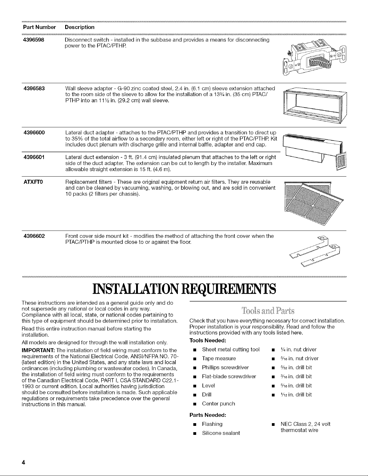
4396598 Disconnect switch - installed in the subbase and provides a means for disconnecting
power to the PTAC/PTHR
4396583
4396600 Lateral duct adapter - attaches to the PTAC/PTHP and provides a transition to direct up
4396601 Lateral duct extension - 3 ft. (91.4 cm) insulated plenum that attaches to the left or right
ATXFT0 Replacement filters - These are original equipment return air filters. They are reusable
4_6_2
Wall sleeve adapter - G-90 zinc coated steel, 2.4 in. (6.1 cm) sleeve extension attached
to the room side of the sleeve to allow for the installation of a 133/4in. (35 cm) PTAC/
PTHP into an 11_/2in. (29.2 cm) wall sleeve.
to 35% of the total airflow to a secondary room, either left or right of the PTAC/PTHR Kit
includes duct plenum with discharge grille and internal baffle, adapter and end cap.
side of the duct adapter. The extension can be cut to length by the installer. Maximum
allowable straight extension is 15 ft. (4.6 m).
and can be cleaned by vacuuming, washing, or blowing out, and are sold in convenient
10 packs (2 filters per chassis).
Front cover side mount kit - modifies the method of attaching the front cover when the
PTAC/PTHP is mounted close to or against the floor.
INSTALLATIONREQUIREMENTS
These instructions are intended as a general guide only and do
not supersede any national or local codes in any way.
Compliance with all local, state, or national codes pertaining to
this type of equipment should be determined prior to installation.
Read this entire instruction manual before starting the
installation.
All models are designed for through the wall installation only.
IMPORTANT: The installation of field wiring must conform to the
requirements of the National Electrical Code, ANSI/NFPA NO. 70-
(latest edition) in the United States, and any state laws and local
ordinances (including plumbing or wastewater codes). In Canada,
the installation of field wiring must conform to the requirements
of the Canadian Electrical Code, PART I, CSA STANDARD C22.1 -
1993 or current edition. Local authorities having jurisdiction
should be consulted before installation is made. Such applicable
regulations or requirements take precedence over the general
instructions in this manual.
Check that you have everything necessary for correct installation.
Proper installation is your responsibility. Read and follow the
instructions provided with any tools listed here.
Tools Needed:
• Sheet metal cutting tool
• Tape measure
• Phillips screwdriver
• Flat-blade screwdriver
• Level
• Drill
• Center punch
Parts Needed:
• Flashing • NEC Class 2, 24volt
• Silicone sealant
• V4in. nut driver
• %6in. nut driver
• %2in. drill bit
• 3/_6in. drill bit
• ¾ein. drill bit
• _/_in. drill bit
thermostat wire

ThisPTAC/PTHPisintendedtobeinstalledthroughan
exteriorwallofthebuildingwherethewallis6in.(15.2cm)to
13in.(33cm)thick.Forlocationswherethewallisadifferent
thickness,see"RequiredParts,Accessories,andOptions."
• This PTAC/PTHP is intended to be installed using a wall
sleeve in a wall opening.
• This PTAC/PTHP may be installed flush with the floor or at
different heights above the floor. See "Required Parts,
Accessories, and Options."
The location shall accommodate the drainage of condensate.
Condensate drainage options include drainage to the exterior
of the building, to the interior of the building or to the wall
interior.
The location shall accommodate the correct electrical
provisions based on the connection method (cord connected
up to 230 volt, direct wired for 265 volt). See "Required Parts,
Accessories, and Options."
IMPORTANT: The instructions indicate the order of installation of
each part or accessory at the point where the component should
be installed. If that accessory or part is not required or is already
installed, then proceed to the next step.
Accessory Kits
The PTAC/PTHP is intended for mounting through an exterior
wall. If the wall is thicker than 13 in. (33 cm), an extension to
the wall sleeve must be used. The PTAC/PTHP should be
installed level or pitched slightly to the outside. The exterior
of the sleeve must be caulked at the building interface.
Electrical
The PTAC/PTHP will have field wiring configurations based upon
the specific installation. Additional wiring options include:
• Disconnect switch kit installed in the subbase provides a
means for disconnecting power to the PTAC/PTHR
NOTE: See "Subbase Kit" previous.
• Desk control kit allows the PTAC/PTHP to be turned on or off
from a remote central station via a 24 volt interface.
• Conduit kit with junction box makes the field wiring
connections for direct wired 265 volt models and includes a
means of quick disconnect for easy removal of the chassis. It
can be used with or without the subbase.
NOTE: See "Subbase Kit" previous.
• Digital remote thermostat is a wall mounted remote
thermostat.
• A time delay fuse is provided with 265 volt PTAC/PTHPs.
Wall installation
• Drain kit attaches to the bottom of the wall sleeve for internal
draining of condensate or to the rear wall sleeve flange for
external draining. Recommended on all PTAC/PTHPs to
remove excess condensate. Packaged in quantities of 10.
Wall sleeve extension retrofit kit is a 2.4 in. (6.1 cm) sleeve
extension attached to the room side of the sleeve to allow for
the installation of a 133/4in. (35 cm) PTAC/PTHP into an
111/2in. (29.2 cm) wall sleeve.
• Front cover side mount kit modifies the method of attaching
the front cover.
• Subbase kit Includes leveling legs, side filler panels and
mounting brackets for electrical accessories. Accepts power
disconnect switch and conduit kit.
IMPORTANT: Subbase kit provides PTAC/PTHP support for
walls less than 6 in. (15.2 cm) thick or for any wall structurally
unable to support the chassis weight.
Standard grille (louver) is stamped aluminum, anodized to
resist chalking and oxidation. It consists of heavy-gauge
aluminum alloy in the following finishes: clear, extruded
aluminum and dark bronze acrylic enamel.
Architectural louver is a replacement for the standard louver.
It consists of heavy-gauge aluminum alloy in the following
finishes: clear, extruded aluminum and dark bronze acrylic
enamel.
Lateral duct adapter kit attaches to the PTAC/PTHP and
provides a transition to direct up to 35% of the total airflow to
a secondary room, either left or right of the PTAC/PTHR Kit
includes duct plenum with discharge grille and internal baffle,
adapter and end cap.
Lateral duct extension is a 3 ft (91.4 cm) insulated plenum
that attaches to the left or right side of the duct adapter. The
extension can be cut to length by the installer. Maximum
allowable straight extension is 15 ft (4.6 m).
Electrical Shock Hazard
Plug into a grounded 3 prong outlet.
Do not remove ground prong.
Do not use an adapter.
Do not use an extension cord.
Failure to follow these instructions can result in death,
fire, or electrical shock.
IMPORTANT: Connect PTAC/PTHP to a single-outlet circuit only.
230/208 Volt PTAC/PTHP
All 230/208 volt PTAC/PTHPs are equipped with power cords.
230/208 volt 250 volt Receptacles
PTAC/PTNP and Overcurrent Protection
AMPS 15 20 30
RECEPTACLE (_ @ (_
NEMA Type 6-15R 6-20R 6-30R
The field-supplied cutlet must match plug on service cord and
be within reach of service cord.
265 Volt PTAC/PTHP
All 265 volt PTAC/PTHPs are equipped with pigtail leads for field
wiring.
IMPORTANT:
• Use copper conductors only.
• Wire sizes are per NEC.
• Use on individual branch circuit only.
• Use overcurrent protection indicated on PTAC/PTHP's rating
plate.
• PTAC/PTHP must be grounded to branch circuit.
• Check local codes.
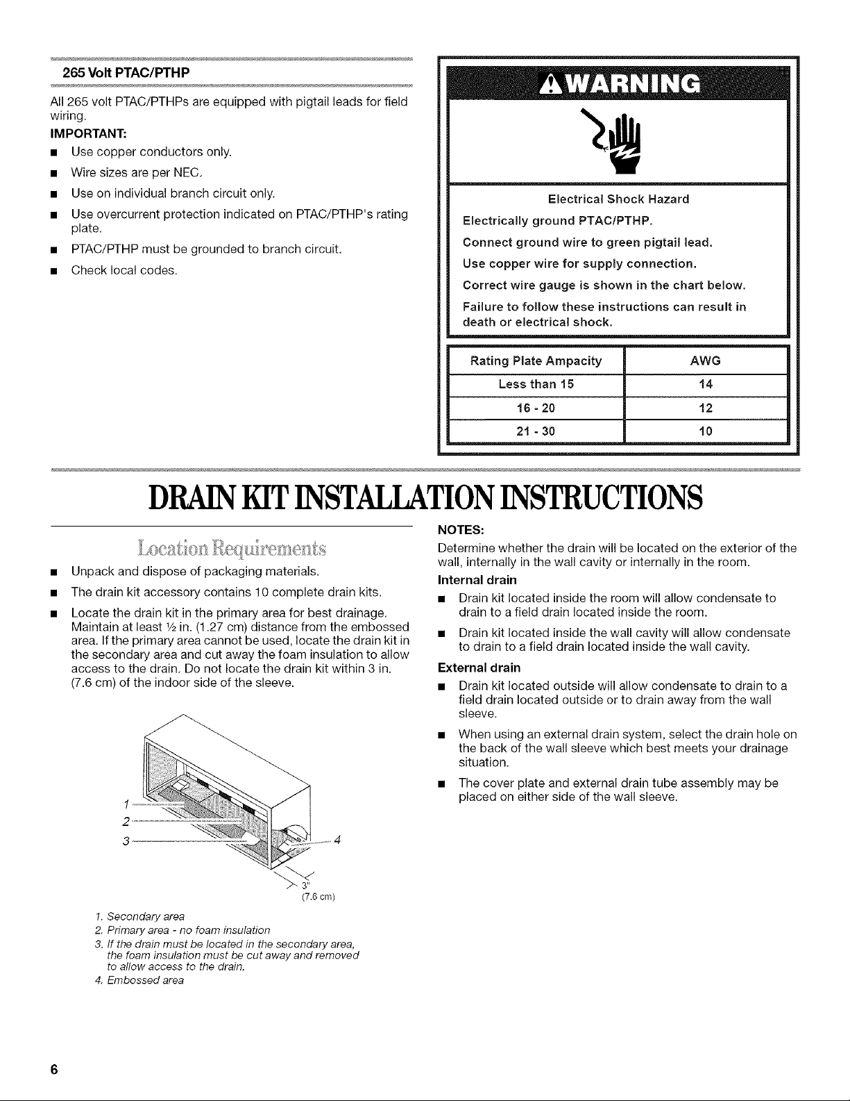
Electrical Shock Hazard
Electrically ground PTAC/PTHP.
Connect ground wire to green pigtail lead.
Use copper wire for supply connection.
Correct wire gauge is shown in the chart below.
Failure to fo!low these instructions can result in
death or electrical shock.
DRAINKITINSTALLATIONINSTRUCTIONS
Unpack and dispose of packaging materials.
The drain kit accessory contains 10 complete drain kits.
Locate the drain kit in the primary area for best drainage.
Maintain at least 1/2in. (1.27 cm) distance from the embossed
area. If the primary area cannot be used, locate the drain kit in
the secondary area and cut away the foam insulation to allow
access to the drain. Do not locate the drain kit within 3 in.
(7.6 cm) of the indoor side of the sleeve.
1
Rating Plate Ampacity
Less than 15
16 - 20
21 - 30
AWG
14
12
10
NOTES:
Determine whether the drain will be located on the exterior of the
wall, internally in the wall cavity or internally in the room.
Internal drain
• Drain kit located inside the room will allow condensate to
drain to a field drain located inside the room.
• Drain kit located inside the wall cavity will allow condensate
to drain to a field drain located inside the wall cavity.
External drain
• Drain kit located outside will allow condensate to drain to a
field drain located outside or to drain away from the wall
sleeve.
• When using an external drain system, select the drain hole on
the back of the wall sleeve which best meets your drainage
situation.
• The cover plate and external drain tube assembly may be
placed on either side of the wall sleeve.
(7.6 cm)
1.Secondary area
2. Primaryarea - no foam insulation
3. If the drain must be located in thesecondary area,
the foam insulation must be cut away and removed
to allow access to the drain.
4. Embossed area

NOTE: If installing an internal drain, install drain kit on the wall
sleeve before the wall sleeve is installed.
1. Using the mounting plate from the drain kit as a template,
mark and drill two 3/_6in. mounting holes and a _/2in. drain
hole at the location chosen above.
2. Remove the backing from the gasket and mount it on the flat
side of the mounting plate. Insert the drain tube through the
hole in the gasket and mounting plate so the tube flange will
be against the wall sleeve.
3
4
5
6
--7
J
1,
Peel the backing tape from the gaskets and mount them on
the curved side of one cover plate and one mounting plate.
2.
Place the drain tube through the gasket and the mounting
plate with the flange toward the wall sleeve.
3.
Using 2 - #10 x _/2in. sheet metal screws (provided), attach
the drain tube assembly to one of the 2 drain holes at the rear
of the wall sleeve.
Position the large flange at the bottom of the sleeve facing
toward the sleeve, and partially tighten the screws. Rotate the
drain tube to a horizontal position to allow for the wall sleeve
to be installed into the wall. Once the wall sleeve is installed,
position the drain tube to the desired angle. Before tightening
the screws, check to be sure the tube's position will allow the
wall sleeve to fit through the wall. Tighten screws.
1.Screw
2. Wallsleeve
3. Gasket
4. Mounting plate
5. Nut
6. Drain tube
7.Optional 4 in. (10.2cm)
straight drain tube
3. Position the assembly beneath the drilled holes and secure it
with #10 - 24 x _/2in. machine screws and Iocknuts (provided).
Seal the tops of the screws with silicone sealant.
4. Connect the drain tube to the drain system in the building.
IMPORTANT: Follow all local building codes when making
this connection.
5,
Attach the 2 cover plates and gaskets over the drain holes at
the rear of the wall sleeve with #10 sheet metal screws
(provided).
NOTE: Check that the 4 overflow slots at the rear of the wall
sleeve are not blocked.
1
--3
4
5
3
4
1. Drain holes
2. Overflow slots
3. Foam gasket
4. Mounting plate
5. #10 x ½in. sheet metal screws
6. ½ in. O.D. tube
7. Optional 4 in. (10.2 cm) straight drain tube
8. Cover plate (no center hole)
4. Using 2 - #10 x _/2in. sheet metal screws (provided), attach
the cover plate to the remaining drain hole. Check that the
large flange on the plate is positioned at the bottom of the
sleeve.
NOTE: Check that the 4 overflow slots at the rear of the wall
sleeve are not blocked.
5. Discard any unused kit parts.
1. Drain holes
2. Overflow slots
3. Gasket
4. Cever plate
5. #10 sheet metal screws

WALLSLEEVEINSTALLATIONINSTRUCTIONS
Wall Opening Requirements
IMPORTANT: The wall sleeve is designed for walls that are 13 in.
(33 cm) in depth or less. For deeper walls, an accessory wall
sleeve extension is required.
• Provide a support lintel if the wall sleeve is installed in a
concrete or masonry wall.
• An accessory drain kit is required for the elimination of PTAC/
PTHP condensate.
When installing a drain kit, it is recommended that the
installation of the drain kit be completed before installing the
wall sleeve. See "Required Parts, Accessories and Options"
and "Drain Kit Installation Instructions."
• Unpack and dispose of packaging materials.
NOTE: Do not remove weatherboard and center support from
wall sleeve until ready to install chassis and outdoor grille.
IMPORTANT:
• If additional support for the wall sleeve is required, or the wall
sleeve projects more than 8 in. (20.3 cm) into the room, an
accessory subbase must be used. See "Subbase Installation
Instructions."
• If a hole is to be cut into an existing wall to install the sleeve,
disconnect power to all wires within the wall.
Refer to the following illustration for proper dimensions and
location of wall opening and the placement of the electrical
outlet.
Wall opening with lintel
1. Main studs 4. Mounting screw holes
2. Jack studs 5. No holes in bottom of wall
3. Lintel sleeve unless drain kit is used
Typical wall sleeve installation
1. Lintel to support masonry walls
2. Electrical outlet
3. Wall opening
NOTE: Construct wall opening to comply with all applicable
building codes.
4. Wall sleeve
5. Insulation
6. Smooth side of screw clip
facing into room

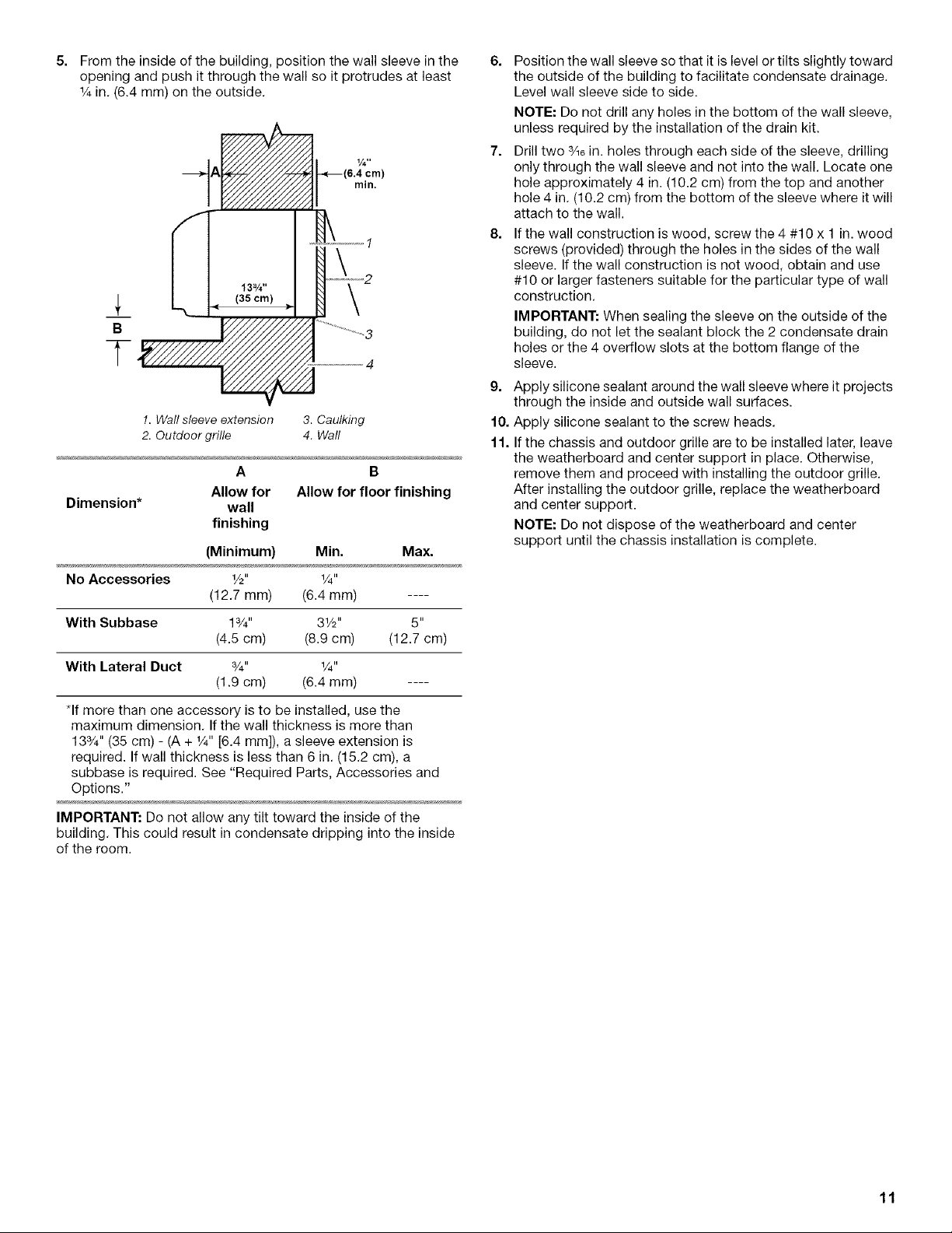
1. Fromtheinsideofthebuilding,positionthewallsleeveinthe
openingandpushitthroughthewallsoitprotrudesatleast
1/4in.(6.4mm)ontheoutside.
±
B
1. Outdoor grille 3. Caulking
2. Wall sleeve 4. Wall
A B
Allow for Allow for floor finishing
Dimension* wall
finishing
(Minimum) Min. Max.
No Accessories 1/2" 1/4"
(12.7 mm) (6.4 mm) ....
With Subbase 13/4" 31/2'' 5"
(4.5 cm) (8.9 cm) (12.7 cm)
With Lateral Duct 3/4" 1/4"
(1.9 cm) (6.4 mm) ....
*If more than one accessory is to be installed, use the
maximum dimension. If the wall thickness is more than
133/4'' (35 cm) - (A + 1/4"[6.4 mm]), a sleeve extension is
required. If wall thickness is less than 6 in. (15.2 cm), a
subbase is required. See "Required Parts, Accessories and
Options."
2=
Position the wall sleeve so that it is level or tilts slightly toward
the outside of the building to facilitate condensate drainage.
Level wall sleeve side to side.
NOTE: Do not drill any holes in the bottom of the wall sleeve,
unless required by the installation of the drain kit.
3=
Drill two 3/16in. holes through each side of the sleeve, drilling
only through the wall sleeve and not into the wall. Locate one
hole approximately 4 in. (10.2 cm) from the top and another
hole 4 in. (10.2 cm) from the bottom of the sleeve where it will
attach to the wall.
4.
If the wall construction is wood, screw the 4 #10 x 1 in. wood
screws (provided) through the holes in the sides of the wall
sleeve. If the wall construction is not wood, obtain and use
#10 or larger fasteners suitable for the particular type of wall
construction.
IMPORTANT: When sealing the sleeve on the outside of the
building, do not let the sealant block the 2 condensate drain
holes or the 4 overflow slots at the bottom flange of the
sleeve.
5=
Apply silicone sealant around the wall sleeve where it projects
through the inside and outside wall surfaces.
6.
Apply silicone sealant to the screw heads.
7.
If the chassis and outdoor grille are to be installed later, leave
the weatherboard and center support in place. Otherwise,
remove them and proceed with installing the outdoor grille.
After installing the outdoor grille, replace the weatherboard
and center support.
NOTE: Do not dispose of the weatherboard and center
support until the chassis installation is complete.
IMPORTANT: Do not allow any tilt toward the inside of the
building. This could result in condensate dripping into the inside
of the room.

WALLSLEEVEEXTENSION
INSTAUATION INSTRUCTIONS
The PTAC/PTHP is intended for mounting through an exterior
wall. If the wall is thicker than 13 in. (33 cm), an extension to
the wall sleeve must be used. The PTAC/PTHP should be
installed level or pitched slightly to the outside. The exterior
of the sleeve must be caulked at the building interface.
• Unpack and dispose of packaging materials.
NOTE: Do not remove weatherboard and center support from
wall sleeve until ready to install chassis and outdoor grille.
Construct and install flashing into wall cutout, as shown.
2,
Run a bead of silicone sealant along the perimeter of the
flashing.
3.
Attach wall sleeve extension to the wall sleeve using 4 sheet
metal screws (provided).
NOTE: Do not overtighten the screws. The wall sleeve
extension is aluminum, and overtightening will strip out the
holes.
8
mlmf Jy
1.Front edge 6. Wall
2. Flashing 7.Drip edge must extend
3. 2 in. (5.03 cm) minimum below wall opening
4. Depth of wall 8. Outsideedge
5. Silicone sealantaround perimeter
_5
Wallsleeveextensions--maximum of 3 may be used.
4,
7
Run a bead of silicone sealant along the bottom mating
surfaces of the wall sleeve and the wall sleeve extension. Run
this bead at least 3 in. (7.6 cm) up the side seams.
2
1. Seal up this edge at least 3 in. (7.6 cm) on
both sides.
2. Seal this entire surface.
IMPORTANT: If using a wall sleeve extension and internal drain
kit, after installing the flashing, run a bead of silicone sealant
between the flashing and the wall sleeve and extension assembly
where the hole was drilled for the drain tube.
10
5. From the inside of the building, position the wall sleeve in the
opening and push it through the wall so it protrudes at least
1/4in. (6.4 mm) on the outside.
1/4"
cm)
min.
B
1. Wall sleeve extension 3. Caulking
2. Outdoor grllle 4. Wall
A B
Allow for Allow for floor finishing
Dimension* wall
finishing
(Minimum) Min. Max.
No Accessories 1/2" 1/4"
(12.7 mm) (6.4 mm) ....
With Subbase 13/4" 31/2'' 5"
(4.5 cm) (8.9 cm) (12.7 cm)
With Lateral Duct 3/4" 1/4"
(1.9 cm) (6.4 mm) ....
6=
Position the wall sleeve so that it is level or tilts slightly toward
the outside of the building to facilitate condensate drainage.
Level wall sleeve side to side.
NOTE: Do not drill any holes in the bottom of the wall sleeve,
unless required by the installation of the drain kit.
7.
Drill two 3/16in. holes through each side of the sleeve, drilling
only through the wall sleeve and not into the wall. Locate one
hole approximately 4 in. (10.2 cm) from the top and another
hole 4 in. (10.2 cm) from the bottom of the sleeve where it will
attach to the wall.
8=
If the wall construction is wood, screw the 4 #10 x 1 in. wood
screws (provided) through the holes in the sides of the wall
sleeve. If the wall construction is not wood, obtain and use
#10 or larger fasteners suitable for the particular type of wall
construction.
IMPORTANT: When sealing the sleeve on the outside of the
building, do not let the sealant block the 2 condensate drain
holes or the 4 overflow slots at the bottom flange of the
sleeve.
g=
Apply silicone sealant around the wall sleeve where it projects
through the inside and outside wall surfaces.
10.
Apply silicone sealant to the screw heads.
11.
If the chassis and outdoor grille are to be installed later, leave
the weatherboard and center support in place. Otherwise,
remove them and proceed with installing the outdoor grille.
After installing the outdoor grille, replace the weatherboard
and center support.
NOTE: Do not dispose of the weatherboard and center
support until the chassis installation is complete.
*If more than one accessory is to be installed, use the
maximum dimension. If the wall thickness is more than
133/4'' (35 cm) - (A + 1/4"[6.4 mm]), a sleeve extension is
required. If wall thickness is less than 6 in. (15.2 cm), a
subbase is required. See "Required Parts, Accessories and
Options."
IMPORTANT: Do not allow any tilt toward the inside of the
building. This could result in condensate dripping into the inside
of the room.
11

STANDARDGRILLEINSTALLATIONINSTRUCTIONS
NOTE: Unpack and dispose of packaging materials.
1. Remove the center support and weatherboard, if still installed
in the wall sleeve.
!. Wall sleeve
2. Weatherboard
3. Center support
2,
Insert 6 plastic grommets into the outdoor grille openings
from the outside of the grille.
4.
Grasp the grille by the attached plastic handles. Position it
with the condensate drain knockouts facing down. From the
inside of the building, maneuver the grille through the wall
sleeve and pull toward you until the screw heads are inserted
into the keyhole slots at the top of the wall sleeve. Tighten the
2 screws.
2 ¸
1. Plastic handles
2. Plastic grommets
3. Condensate drain knockouts
3,
Insert 2 - #8 x % in. sheet metal screws (provided) in the top
2 outside edge plastic grommets. Tighten the screws halfway
into the grommets.
!. Plastic handles
2. Plastic grommets
3. Condensate drain knockouts
5,
Insert the remaining screws into the remaining holes and into
the grommets and tighten all screws.
12
ARCHITECTURALLOUVER
INSTAilATION INSTRUCTIONS
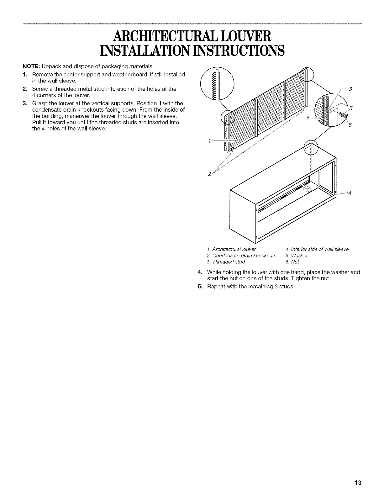
NOTE: Unpack and dispose of packaging materials.
1. Remove the center support and weatherboard, if still installed
in the wall sleeve.
2. Screw a threaded metal stud into each of the holes at the
4 corners of the louver.
3. Grasp the louver at the vertical supports. Position it with the
condensate drain knockouts facing down. From the inside of
the building, maneuver the louver through the wall sleeve.
Pull it toward you until the threaded studs are inserted into
the 4 holes of the wall sleeve.
!. Architectural louver 4. Interior side of wall sleeve
2. Condensate drainknockouts 5. Washer
3. Threaded stud 6. Nut
4.
While holding the louver with one hand, place the washer and
start the nut on one of the studs. Tighten the nut.
5.
Repeat with the remaining 3 studs.
13
WAILSLEEVEADAPTERKIT
INSTALLATIONINSTRUCTIONS
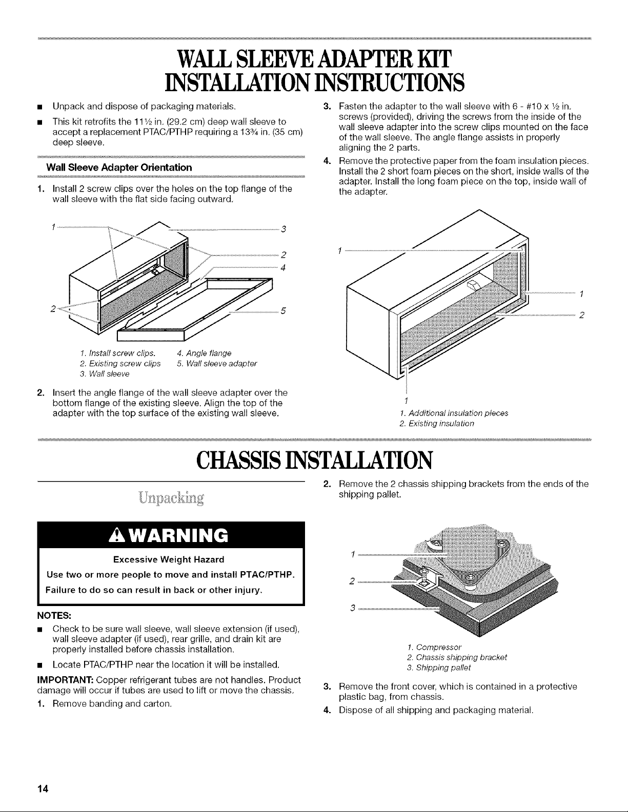
• Unpack and dispose of packaging materials.
• This kit retrofits the 111/2in. (29.2 cm) deep wall sleeve to
accept a replacement PTAC/PTHP requiring a 133/4in. (35 cm)
deep sleeve.
Wall Sleeve Adapter Orientation
1. Install 2 screw clips over the holes on the top flange of the
wall sleeve with the flat side facing outward.
1
1. Install screw clips. 4. Angle flange
2. Existing screw clips 5. Wall sleeve adapter
3. Wall sleeve
2=
Insert the angle flange of the wall sleeve adapter over the
bottom flange of the existing sleeve. Align the top of the
adapter with the top surface of the existing wall sleeve.
3
2
4
3. Fasten the adapter to the wall sleeve with 6 - #10 x 1/2in.
screws (provided), driving the screws from the inside of the
wall sleeve adapter into the screw clips mounted on the face
of the wall sleeve. The angle flange assists in properly
aligning the 2 parts.
4. Remove the protective paper from the foam insulation pieces.
Install the 2 short foam pieces on the short, inside walls of the
adapter. Install the long foam piece on the top, inside wall of
the adapter.
1
2
1.Additional insulation pieces
2. Existing insulation
CHASSISINSTALLATION
NOTES:
• Check to be sure wall sleeve, wall sleeve extension (if used),
wall sleeve adapter (if used), rear grille, and drain kit are
properly installed before chassis installation.
• Locate PTAC/PTHP near the location it will be installed.
IMPORTANT: Copper refrigerant tubes are not handles. Product
damage will occur if tubes are used to lift or move the chassis.
1. Remove banding and carton.
2. Remove the 2 chassis shipping brackets from the ends of the
shipping pallet.
!. Compressor
2. Chassis shipping bracket
3. Shipping pallet
3. Remove the front cover, which is contained in a protective
plastic bag, from chassis.
4. Dispose of all shipping and packaging material.
14
 Loading...