

Page 1
CONSUMER SERVICES TECHNICAL
EDUCATION GROUP PRESENTS
PACKAGED
TERMINAL
AIR
CONDITIONERS
R-99
Models: ATE0743SPP, ATE0943SPP, ATE1243SPP, ATE1545SPP,
ATR0743SPP, ATR0943SPP, ATR1243SPP, ATR1545SPP
ATE0953SPP, ATE1253SPP,ATE1555SPP,
ATR0953SPP, ATR1253SPP,ATR1555SPP,
ATE0743RPP, ATE0943RPP, ATE1243RPP, ATE1545RPP,
ATR0743RPP, ATR0943RPP, ATR1243RPP, ATR1545RPP
JOB AID
Part No. 8178315
Page 2

FORWARD
This Whirlpool Job Aid, “Packaged Terminal Air Conditioners” (Part No. 8178315), provides the
technician with information on the installation, operation, and service of the Packaged Terminal Air
Conditioners . It is to be used as a training Job Aid and Service Manual. For specific information
on the model being serviced, refer to the “Use and Care Guide,” or “Tech Sheet” provided with the
air conditioner.
The Wiring Diagrams and Strip Circuits used in this Job Aid are typical and should be used for
training purposes only. Always use the Wiring Diagram supplied with the product when servicing
the unit.
GOALS AND OBJECTIVES
The goal of this Job Aid is to provide detailed information that will enable the service technician to
properly diagnose malfunctions and repair the Packaged Terminal Air Conditioners.
The objectives of this Job Aid are to:
• Understand and follow proper safety precautions.
• Successfully troubleshoot and diagnose malfunctions.
• Successfully perform necessary repairs.
• Successfully return the air conditioner to its proper operational status.
WHIRLPOOL CORPORATION assumes no responsibility for any repairs made
on our products by anyone other than Authorized Service Technicians.
Copyright © 2004, Whirlpool Corporation, Benton Harbor, MI 49022
- ii -
Page 3

TABLE OF CONTENTS
Page
GENERAL............................................................................................................................... 1-1
Whirlpool Model & Serial Number Designations ................................................................ 1-1
Model & Serial Number Label & Wiring Diagram Locations .............................................. 1-2
Specifications..................................................................................................................... 1-3
Whirlpool Packaged Terminal Air Conditioner (PTAC) And
Packaged Terminal Heat Pump (PTHP) Warranty ......................................................... 1-4
INSTALLATION INFORMATION ........................................................................................... 2-1
Electrical Requirements ..................................................................................................... 2-1
Drain Kit Installation ........................................................................................................... 2-2
Chassis Installation ............................................................................................................ 2-5
Remote Wall Thermostat Installation ................................................................................. 2-9
PRODUCT OPERATION ........................................................................................................ 3-1
Theory Of Operation .......................................................................................................... 3-1
Refrigeration Operation .................................................................................................. 3-1
Heat Pump Operation .................................................................................................... 3-3
Reversing Valve Operation ............................................................................................ 3-4
Remote Thermostat Operation....................................................................................... 3-5
Heat Pump Function ...................................................................................................... 3-7
Operating The Controls ..................................................................................................... 3-8
COMPONENT ACCESS ......................................................................................................... 4-1
Component Locations ........................................................................................................ 4-1
Removing The Indoor Thermostat, Mode (System) Switch, And Heat Anticipator ............ 4-2
Removing The Power Supply Cord ................................................................................... 4-4
Removing The Defrost Thermostat.................................................................................... 4-5
Removing The Hot Start Relay And Hot Start Sensor ....................................................... 4-6
Removing The Capacitor & Fan Cycle Switch ................................................................... 4-7
Removing The Remote Control Unit Fan Switch ............................................................... 4-8
Removing The Heater & Limit Switch ................................................................................ 4-9
Removing The Fan Motor ................................................................................................ 4-10
Removing The Condensate Valve Bellows...................................................................... 4-13
Removing The Overload Protector And The Compressor ............................................... 4-14
Removing The Evaporator ............................................................................................... 4-16
Removing The Condenser ............................................................................................... 4-18
Removing The Solenoid Coil & Reversing Valve............................................................. 4-20
- iii -
Page 4

COMPONENT TESTING ........................................................................................................ 5-1
Indoor Thermostat ............................................................................................................. 5-1
Mode (System) Switch ....................................................................................................... 5-2
Heat Anticipator ................................................................................................................. 5-2
Defrost Thermostat (Emergency Heat Switch) .................................................................. 5-3
Hot Start Relay .................................................................................................................. 5-4
Hot Start Sensor ................................................................................................................ 5-4
Capacitor ........................................................................................................................... 5-5
Fan Cycle Switch & Remote Control Unit Fan Switch ....................................................... 5-5
Heater & Limit Switch ........................................................................................................ 5-6
Fan Motor ......................................................................................................................... 5-6
Overload Protector............................................................................................................. 5-7
Compressor ....................................................................................................................... 5-7
Solenoid Coil...................................................................................................................... 5-8
DIAGNOSIS & TROUBLESHOOTING ................................................................................... 6-1
Diagnosing The Sealed System ........................................................................................ 6-1
Troubleshooting Charts ..................................................................................................... 6-7
WIRING DIAGRAMS & STRIP CIRCUITS ............................................................................. 7-1
Wiring Diagrams ................................................................................................................ 7-5
Strip Circuits .................................................................................................................... 7-10
TECH TIPS ............................................................................................................................. 8-1
Routine Maintenance ......................................................................................................... 8-1
Accessories ....................................................................................................................... 8-2
Optional Desk Control Unit ................................................................................................ 8-4
General Troubleshooting ................................................................................................... 8-5
- iv -
Page 5
GENERAL
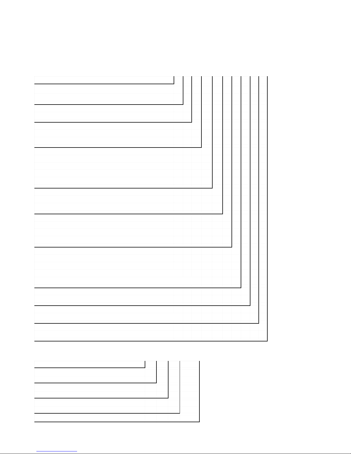
WHIRLPOOL MODEL & SERIAL NUMBER DESIGNATIONS
MODEL NUMBER
MODEL NUMBER A T R 12 4 3 S P P 0
PRODUCT GROUP
A = AIR CONDITIONER
PRODUCT IDENTIFICATION
T = PTAC, WHIRLPOOL
MODEL TYPE
R = HEAT PUMP W/AUXILIARY HEAT
E = COOLING W/ELECTRIC HEAT
NOMINAL COOLING CAPACITY
07 = 7,000 BTU/HR
09 = 9,000 BTU/HR
12 = 12,000 BTU/HR
15 = 15,000 BTU/HR
ELECTRICAL CODE
4 = 208V-230V, 1 PHASE, 60 HZ
5 = 265V, 1 PHASE, 60 HZ
HEATER
2 = 2.5 KW
3 = 3.4 KW
5 = 5.0 KW
FEATURE CODE OPTIONS
S = STANDARD ELECTROMECHANICAL
R = REMOTE WALL-MOUNTED THERMOSTAT
C = SEACOAST PROTECTION / STD. CONTROLS
B = REMOTE THERMOSTAT / SEACOAST PROTECTION
MANUFACTURING LOCATION
P = PURCHASED PRODUCT
YEAR OF INTRODUCTION
M = 2003, P = 2004, R = 2005, S = 2006, T = 2007
ENGINEERING CHANGE
0, 1, 2, ETC.
SERIAL NUMBER
SERIAL NUMBER QR P 05 21234
MANUFACTURING RESPONSIBILITY
QR = FRIEDRICH MANUFACTURING CO.
YEAR OF PRODUCTION
P = 2003, R = 2004
WEEK OF PRODUCTION
5TH WEEK
PRODUCT SEQUENCE NUMBER
1-1
Page 6
MODEL & SERIAL NUMBER LABEL &
WIRING DIAGRAM LOCATIONS
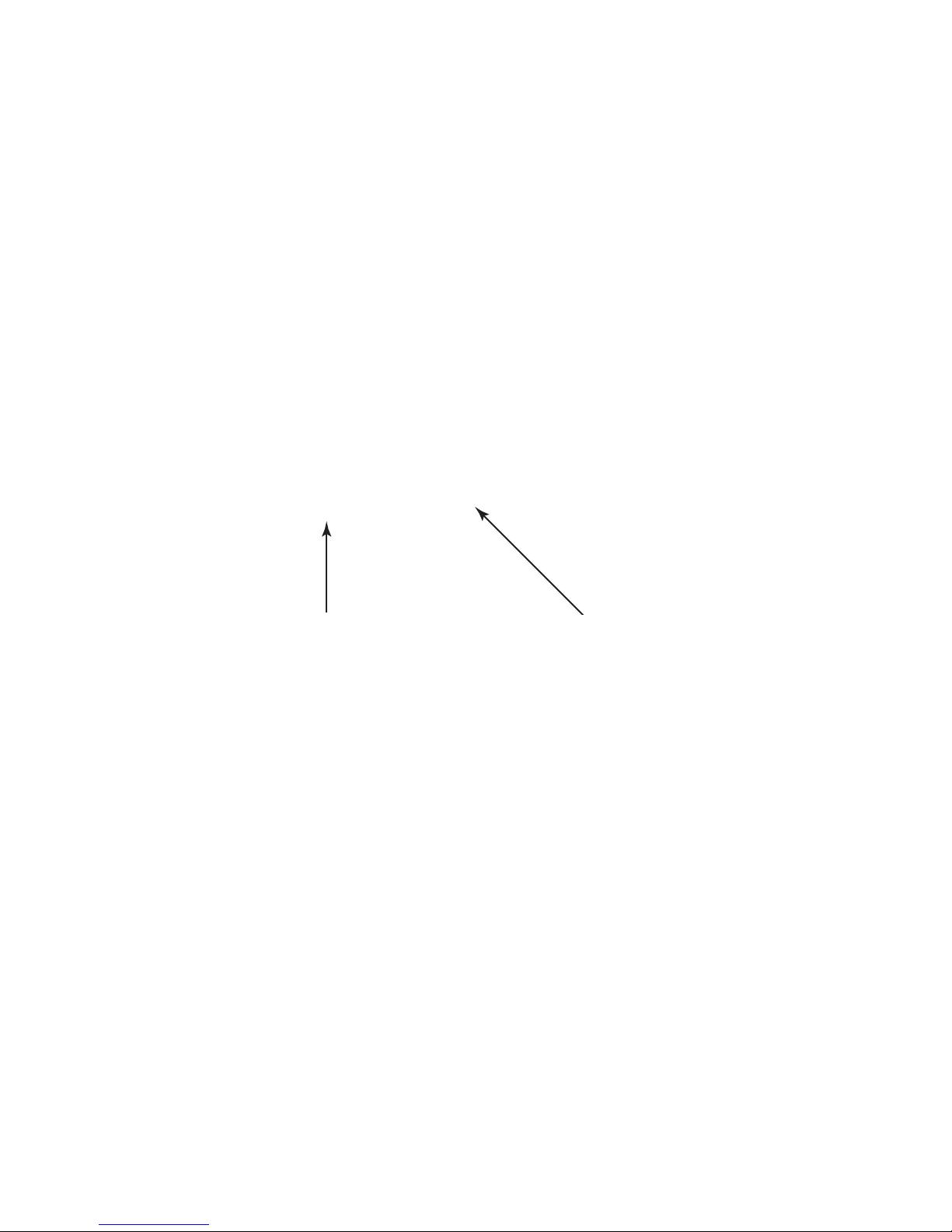
The Model/Serial Number label and Wiring Diagram locations are shown below.
Wiring Diagram Location
(Front Cover Removed)
Model & Serial
Number Location
1-2
Page 7
SPECIFICATIONS
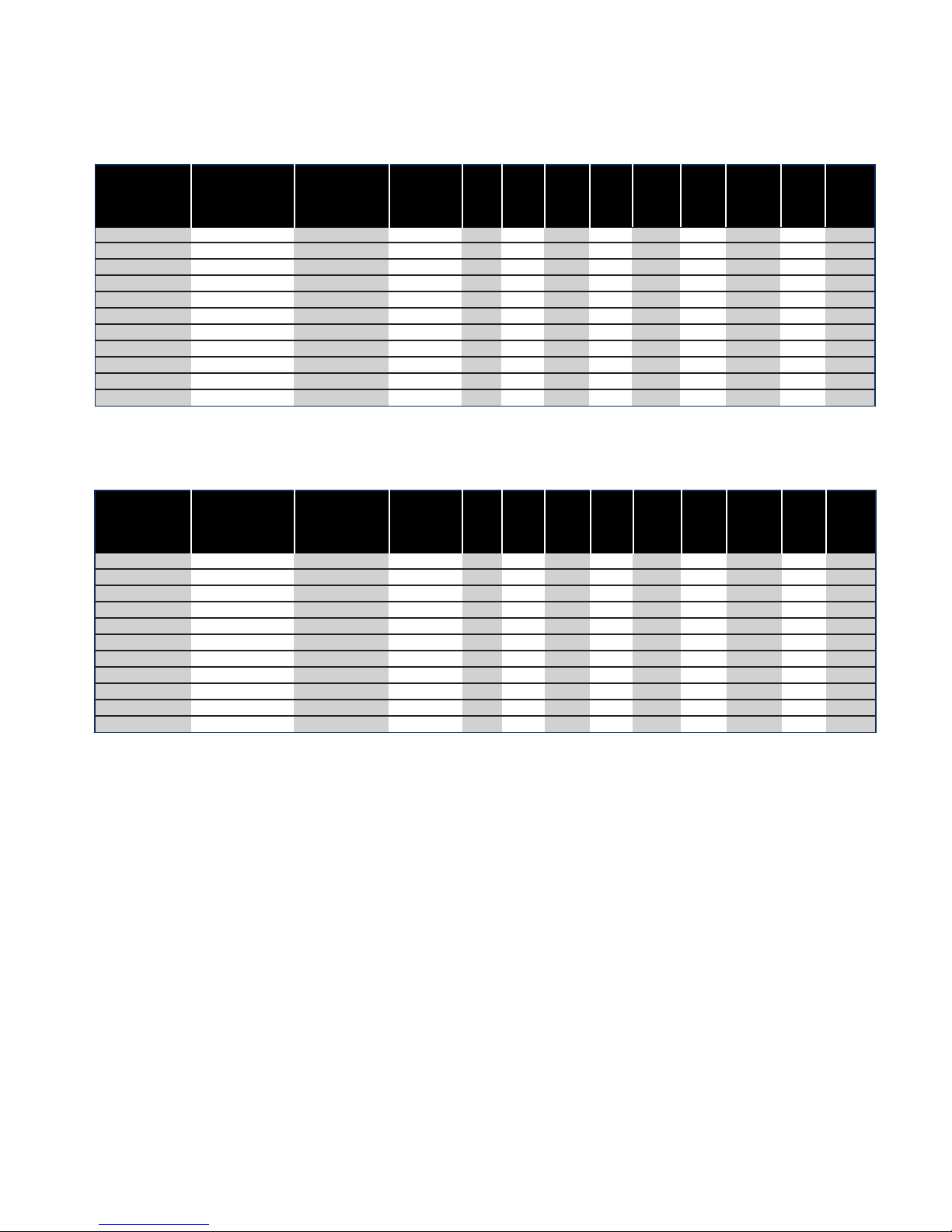
ATE-SERIES PTAC W/ELECTRIC HEAT — COOLING PERFORMANCE
Whirlpool Model
ATE0743SPP Standard 7500/7000 11600 230 3.4 12.2 20 6-20 20 Amp 2.1 250 NA
ATE0943SPP Standard 9200/9000 11600 230 3.4 11.3 20 6-20 20 Amp 2.7 300 NA
ATE1243SPP Standard 12000/12000 11600 230 3.4 10.7 20 6-20 20 Amp 3.8 325 NA
ATE1545SPP Standard 15000-15000 17000 230 5.0 9.5 30 6-30 30 Amp 5.5 350 NA
ATE0953SPP Standard 9200/9000 11600 265 3.4 11.3 20 6-20 20 Amp 2.7 300 NA
ATE1253SPP Standard 12000/12000 11600 265 3.4 10.7 20 6-20 20 Amp 3.8 325 NA
ATE1555SPP Remote 15000/15000 17000 265 5.0 9.5 30 6-20 30 Amp 3.5 350 NA
ATE0743RPP Remote 7500/75000 11600 230 3.4 12.2 20 6-20 20 Amp 2.1 250 NA
ATE0943RPP Remote 9200/9000 11600 230 3.4 11.3 20 6-20 20 Amp 2.7 300 NA
ATE1243RPP Remote 12000/12000 11600 230 3.4 10.7 20 6-20 20 Amp 3.8 325 NA
ATE1545RPP Remote 15000-15000 17000 230 5.0 9.5 30 6-30 30 Amp 5.5 350 NA
Control
Type
Cooling BTU
230/208v
Heating
BTU
Electric
Volts
Heater
KW
EER
Breaker
Amps-
NEMA
Plug
Type*
Plug
Dehum-
Pts/Hr
CFM COP
ATR-SERIES PTHP W/HEATING — COOLING PERFORMANCE
Whirlpool Model
ATR0743SPP Standard 7200/7000 11600 230 3.4 12.1 20 6-20 20 Amp 2.1 250 3.3
ATR0943SPP Standard 9100/9000 11600 230 3.4 10.5 20 6-20 20 Amp 2.1 250 3.3
ATR1243SPP Standard 12000/12000 11600 230 3.4 10.5 20 6-20 20 Amp 2.1 250 3.3
ATR1545SPP Standard 15000/14700 17000 230 5.0 9.3 30 6-30 30 Amp 5.5 350 2.8
ATR0953SPP Standard 9100/9000 11600 265 3.4 11.3 20 6-20 20 Amp 3.8 325 3.1
ATR1253SPP Standard 12000/12000 11600 265 3.4 10.5 20 6-20 20 Amp 3.8 325 3.1
ATR1555SPP Standard 15000/14700 17000 265 5.0 9.3 30 6-30 30 Amp 5.5 350 2.8
ATR0743RPP Remote 7200/7200 11600 230 3.4 12.1 20 6-20 20 Amp 2.1 250 3.3
ATR0943RPP Remote 9100/9000 11600 230 3.4 11.3 20 6-20 20 Amp 2.1 250 3.3
ATR1243RPP Remote 12000/12000 11600 230 3.4 10.5 20 6-20 20 Amp 3.8 325 3.1
ATR1545RPP Remote 15000/14700 17000 230 5.0 9.3 30 6-30 30 Amp 5.5 350 2.8
Control
Type
Cooling BTU
230/208v
Heating
BTU
Electric
Volts
Heater
KW
EER
Breaker
Amps-
NEMA
Plug
Type*
Plug
Dehum-
Pts/Hr
CFM COP
* 15 Amps available on special order models
CFM = Cubic Feet per Minute
COP = Coefficient Of Performance (applies to PTHP only)
1-3
Page 8
WHIRLPOOL PACKAGED TERMINAL
AIR CONDITIONER (PTAC) AND PACKAGED
TERMINAL HEAT PUMP (PTHP) WARRANTY
LENGTH OF WARRANTY:
ONE YEAR FULL WARRANTY
FIVE YEAR FULL WARRANTY
SECOND THROUGH FIFTH YEAR
LIMITED WARRANTY
WHIRLPOOL WILL PAY FOR:
For one year from the date of installation, if this PTAC/PTHP fails
when operated and maintained according to instructions attached
to or furnished with the product, Whirlpool Corporation will pay for
replacement parts and repair labor to correct defects in materials
or workmanship. Service must be provided by a Whirlpool designated service company.
For five years from the date of purchase, if this PTAC/PTHP fails
when operated and maintained according to instructions attached
to or furnished with the product, Whirlpool Corporation will pay for
replacement parts and repair labor to correct defects in materials
or workmanship in the sealed refrigeration system, including the
compressor, evaporator, condenser, reversing valve and connecting tubing. Service must be provided by a Whirlpool designated
service company.
For the second through fifth year from the date of purchase, if this
PTAC/PTHP fails when operated and maintained according to instructions attached to or furnished with the product, Whirlpool Corporation will pay for replacement parts to correct defects in materials or workmanship in the electrical or air flow systems including
the fan motor, capacitor, fan, blower wheel, switches, thermostat,
relays, frost controls, heat control, heater, heater protectors, compressor overload, solenoids, auxiliary controls, and transformer.
This is a limited parts-only warranty and does not include labor or
transportation to and from the service shop. Service must be provided by a Whirlpool designated service company.
WHIRLPOOL WILL NOT PAY FOR:
1. Service calls to correct the installation of the PTAC/PTHP, instruct you how to use the PTAC/PTHP, to replace
fuses, correct wiring, reset circuit breakers, or to clean or replace owner accessible air filters.
2. Damage resulting from accident, alteration, misuse, abuse, fire, floods, acts of God, improper installation not
in accordance with local electrical and plumbing codes, or use of products not approved by Whirlpool
Corporation, or Whirlpool Canada, Inc.
3. Replacement parts or repair labor costs for units operated outside the United States or Canada.
4. Pickup and delivery, or any transportation and reinstallation charges that may be required.
5. The removal and reinstallation of the PTAC/PTHP.
6. Repairs to parts or systems resulting from unauthorized modifications made to the PTAC/PTHP.
WHIRLPOOL CORPORATION AND WHIRLPOOL CANADA, INC. SHALL NOT BE LIABLE FOR INCIDENTAL
OR CONSEQUENTIAL DAMAGES.
Some states and provinces do not allow the exclusion or limitation of incidental or consequential damages, so this
exclusion or limitation may not apply to you. This warranty gives you specific legal rights and you may also have other
rights which vary from state to state or province to province.
Outside the United States and Canada, a different warranty may apply. For details, please contact your
Whirlpool authorized dealer.
If you need service, first see "Troubleshooting" section of the Installation/Operation Manual. After checking
“Troubleshooting,” additional help can be found by checking the “Assistance or Service” section, or by calling the
Whirlpool Corporation Customer Interaction Center at 1-800-253-1301 (toll-free), from anywhere in the United
States. In Canada, please call 1-800-807-6777.
1-4
Page 9
INSTALLATION INFORMATION
ELECTRICAL REQUIREMENTS
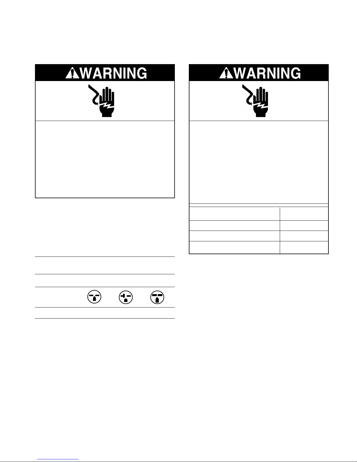
Electrical Shock Hazard
Plug into a grounded 3 prong outlet.
Do not remove ground prong.
Do not use an adapter.
Do not use an extension cord.
Failure to follow these instructions can
result in death, fire, or electrical shock.
IMPORTANT: Connect PTAC/PTHP to a
single-outlet circuit only.
230/208 VOLT PTAC/PTHP
All 230/208 volt PTAC/PTHPs are equipped
with power cords.
230/208 volt 250 volt Receptacles and
PTAC/PTHP Overcurrent Protection
AMPS 15 20 30
RECEPTACLE
Electrical Shock Hazard
Electrically ground PTAC/PTHP.
Connect ground wire to green pigtail lead.
Use copper wire for supply connection.
Correct wire gauge is shown in the chart
below.
Failure to follow these instructions can
result in death or electrical shock.
Rating Plate Ampacity AWG
Less than 15 14
16 - 20 12
21 - 30 10
265 VOLT PTAC/PTHP
All 265 volt PTAC/PTHPs are equipped with
pigtail leads for field wiring.
IMPORTANT:
NEMA Type 6-15R 6-20R 6-30R
The field-supplied outlet must match plug on
service cord and be within reach of service
cord.
• Use copper conductors only.
• Wire sizes are per NEC.
• Use on individual branch circuit only.
• Use overcurrent protection indicated on
PTAC/PTHP’s rating plate.
• PTAC/PTHP must be grounded to branch
circuit.
• Check local codes.
2-1
Page 10
DRAIN KIT INSTALLATION
LOCATION REQUIREMENTS
• Unpack and dispose of packaging materials.
• The drain kit accessory contains 10 complete drain kits.
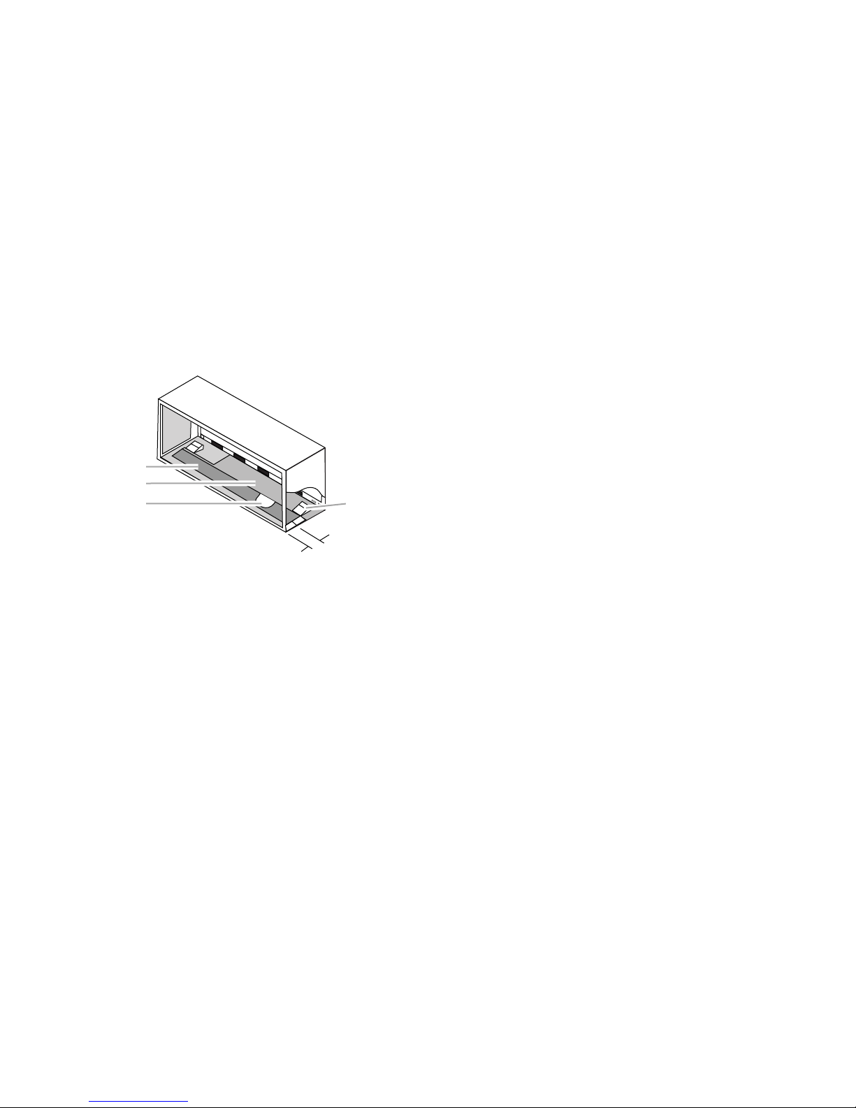
• Locate the drain kit in the primary area for
best drainage. Maintain at least 1/2″ (1.27
cm) distance from the embossed area. If the
primary area cannot be used, locate the
drain kit in the secondary area and cut away
the foam insulation to allow access to the
drain. Do not locate the drain kit within 3″ (7.6
cm) of the indoor side of the sleeve.
1
2
3
1. Secondary area
2. Primary area - no foam insulation
3. If the drain must be located in the secondary area,
the foam insulation must be cut away and removed
to allow access to the drain.
4. Embossed area
4
3"
(7.6 cm)
NOTES:
Determine whether the drain will be located
on the exterior of the wall, internally in the wall
cavity or internally in the room.
Internal Drain
• Drain kit located inside the room will allow
condensate to drain to a field drain located
inside the room.
• Drain kit located inside the wall cavity will
allow condensate to drain to a field drain
located inside the wall cavity.
External Drain
• Drain kit located outside will allow condensate to drain to a field drain located outside
or to drain away from the wall sleeve.
• When using an external drain system, select
the drain hole on the back of the wall sleeve
which best meets your drainage situation.
• The cover plate and external drain tube
assembly may be placed on either side of the
wall sleeve.
2-2
Page 11

INTERNAL DRAIN INSTALLATION
(Located Inside The Wall Cavity Or
In The Interior Of The Room)
NOTE: If installing an internal drain, install drain
kit on the wall sleeve before the wall sleeve is
installed.
1. Using the mounting plate from the drain kit
as a template, mark and drill two 3/16″
mounting holes and a 1/2″ drain hole at the
location chosen above.
2. Remove the backing from the gasket and
mount it on the flat side of the mounting
plate. Insert the drain tube through the
hole in the gasket and mounting plate so
the tube flange will be against the wall
sleeve.
1
2
3
4
5
6
3. Position the assembly beneath the drilled
holes and secure it with #10 - 24 x 1/2″
machine screws and locknuts (provided).
Seal the tops of the screws with silicone
sealant.
4. Connect the drain tube to the drain system
in the building.
IMPORTANT: Follow all local building
codes when making this connection.
5. Attach the 2 cover plates and gaskets over
the drain holes at the rear of the wall
sleeve with #10 sheet metal screws (provided).
NOTE: Check that the 4 overflow slots at
the rear of the wall sleeve are not blocked.
1
3
4
5
1. Screw
2. Wall sleeve
3. Gasket
4. Mounting p late
5. Nut
6. Drain tube
7. Optional 4 in. (10.2 cm)
straight drain tube
1
2
1. Drain holes
2. Overflow slots
3. Gasket
4. Cover plate
5. #10 sheet metal screws
2-3
Page 12
EXTERNAL DRAIN INSTALLATION
(Located On The Exterior
Of The Wall)
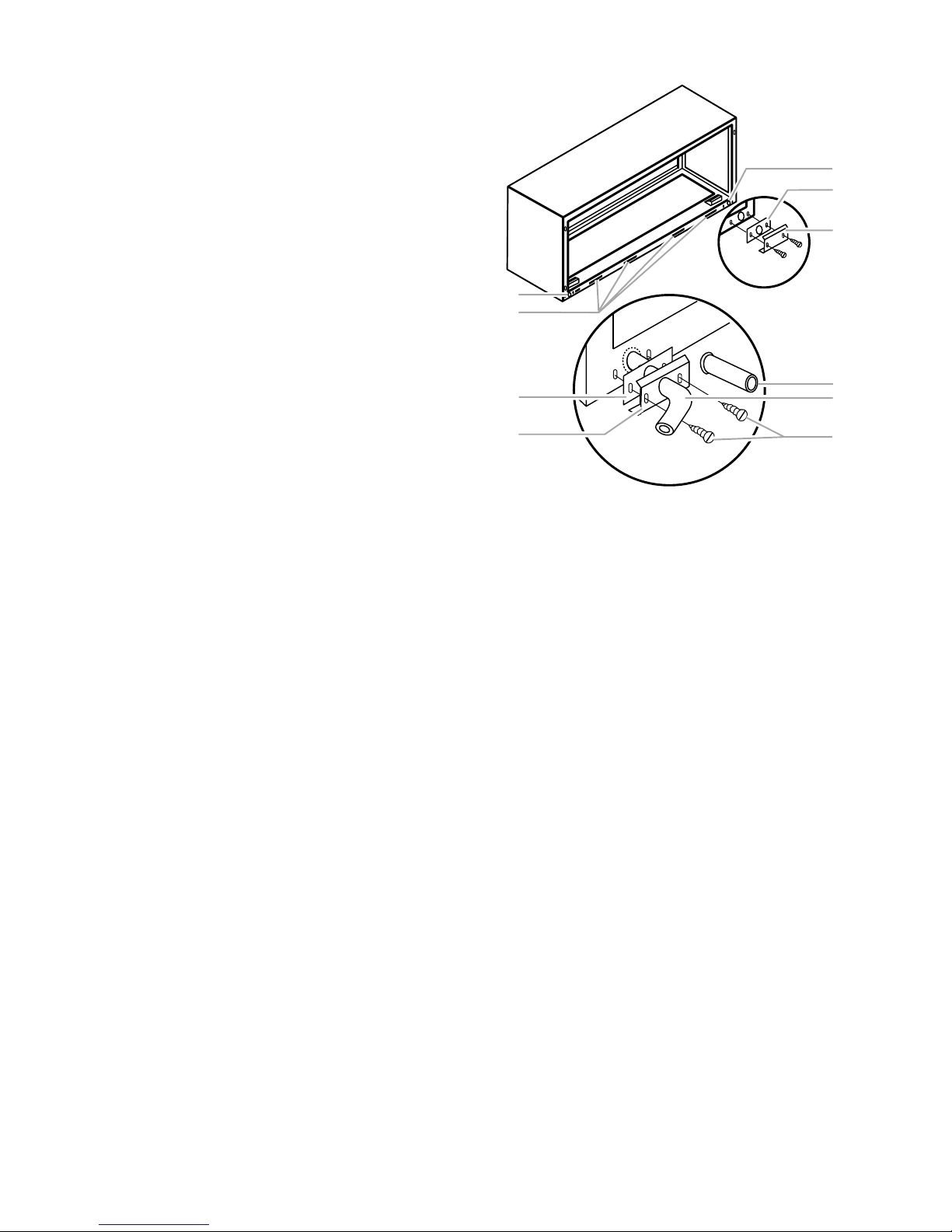
1. Peel the backing tape from the gaskets
and mount them on the curved side of one
cover plate and one mounting plate.
2. Place the drain tube through the gasket
and the mounting plate with the flange
toward the wall sleeve.
3. Using 2 - #10 x 1/2″ sheet metal screws
(provided), attach the drain tube assembly
to one of the 2 drain holes at the rear of the
wall sleeve.
Position the large flange at the bottom of
the sleeve facing toward the sleeve, and
partially tighten the screws. Rotate the
drain tube to a horizontal position to allow
for the wall sleeve to be installed into the
wall. Once the wall sleeve is installed,
position the drain tube to the desired angle.
Before tightening the screws, check to be
sure the tube’s position will allow the wall
sleeve to fit through the wall. Tighten screws.
1
3
8
1
2
3
4
1. Drain holes
2. Overflow slots
3. Foam gasket
4. Mounting plate
5. #10 x 1/2 in. sheet metal screws
6. 1/2 in. O.D. tube
7.
Optional 4 in. (10.2 cm) straight drain tube
Cover plate (no center hole)
8.
7
6
5
4. Using 2 - #10 x 1/2″ sheet metal screws
(provided), attach the cover plate to the
remaining drain hole. Check that the large
flange on the plate is positioned at the
bottom of the sleeve.
NOTE: Check that the 4 overflow slots at
the rear of the wall
5. Discard any unused kit parts.
2-4
Page 13
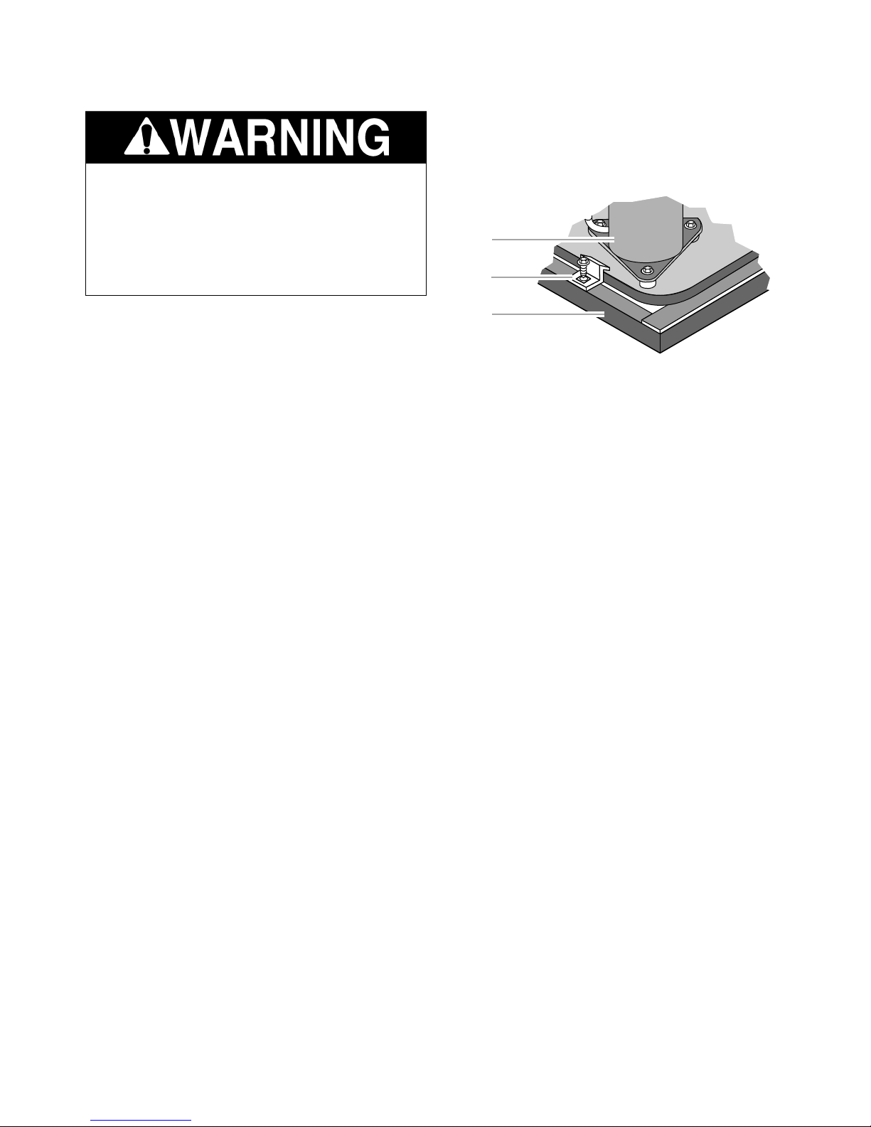
CHASSIS INSTALLATION
Excessive Weight Hazard
Use two or more people to move and
install PTAC/PTHP.
Failure to do so can result in back or other
injury.
1. Remove banding and carton.
2. Remove the 2 chassis shipping brackets
from the ends of the shipping pallet.
1
2
NOTES:
• Check to be sure wall sleeve, wall sleeve
extension (if used), wall sleeve adapter (if
used), rear grille, and drain kit are properly
installed before chassis installation.
• Locate PTAC/PTHP near the location it will
be installed.
IMPORTANT: Copper refrigerant tubes are not
handles. Product damage will occur if tubes
are used to lift or move the chassis.
3
1. Compressor
2. Chassis shipping bracket
3. Shipping pallet
3. Remove the front cover, which is contained in a protective plastic bag, from
chassis.
4. Dispose of all shipping and packaging material.
2-5
Page 14
INSTALL THE CHASSIS
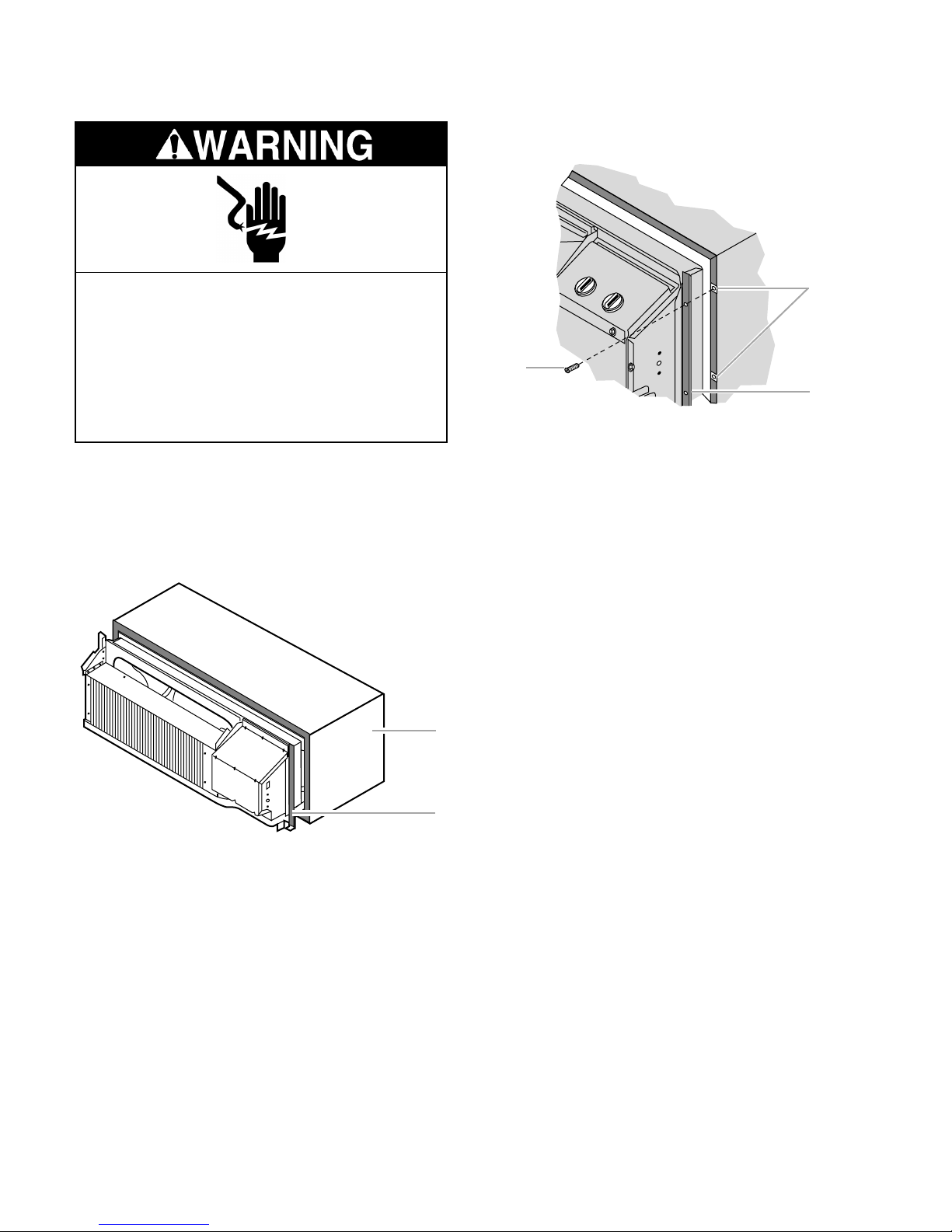
3. Locate the 4 - #10 x 1″ chassis mounting
screws (provided). Tighten the screws into
the wall sleeve screw clips.
Electrical Shock Hazard
Disconnect power before servicing.
Replace all parts and panels before
operating.
Failure to do so can result in death or
electrical shock.
1. Disconnect power.
2. Center the chassis in the installed sleeve
and carefully push the chassis until the
chassis flange and gasket contact the
sleeve flange.
2
1
3
1. Chassis mounting screw
2. Screw clips
3. Chassis flange
4. Install the front cover by placing the top of
the front cover onto the metal flange at the
top of the chassis. Rotate the front cover
into place. Insert the thumbscrews (provided) into the slots located at the bottom
back corners of the front cover. Tighten to
secure the cover.
NOTE: If the unit has been placed in such
a way that there is no room to insert the
thumbscrews from the bottom, a side
mounting kit may be used.
1
MAKE ELECTRICAL CONNECTIONS
1. Wall sleeve
2. Chassis flange and gasket
2
IMPORTANT: The installation of field wiring
must conform to the requirements of the National Electrical Code, ANSI/NFPA NO. 70 (latest edition) in the United States, and any state
laws and local ordinances (including plumbing
or wastewater codes). In Canada, field wiring
must conform to the Canadian electrical code
PART I, CSA STANDARD C22.1-1993 or current edition. Local authorities having jurisdiction should be consulted before installation is
made. Such applicable regulations or requirements take precedence over the general instructions in this Job Aid.
2-6
Page 15
Cord Connected Models
Electrical Shock Hazard
Plug into a grounded 3 prong outlet.
Do not remove ground prong.
FIELD WIRING CONNECTIONS
1. Disconnect power.
2. Remove the PTAC/PTHP front cover using the thumbscrews.
3. Route the incoming power supply through
suitable conduit to the PTAC/PTHP control box.
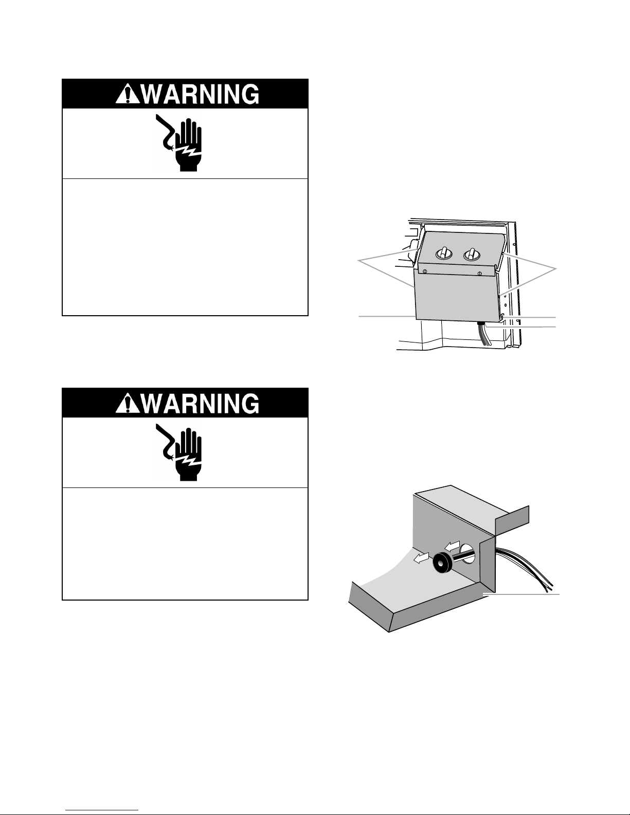
4. Remove the 4 screws holding the control
box.
Do not use an adapter.
Do not use an extension cord.
Failure to follow these instructions can
result in death, fire, or electrical shock.
1. Plug into a grounded 3 prong outlet.
2. Reconnect power.
Direct Wired Models
Electrical Shock Hazard
Disconnect power before servicing.
Replace all parts and panels before
operating.
Failure to do so can result in death or
electrical shock.
1
2
1. Remove these screws.
2. Do not remove these screws.
3. Bushing
1
2
3
5. Pivot the control box down, pull the chassis pigtail wires into the control box, and
remove the bushing from the hole. The
field-supplied wires will be routed through
this hole.
1
2
Field wiring connections for direct-wired models can be done in one of 2 ways:
• Using field-supplied conduit and wires.
• Using the Conduit with Junction Box Kit
accessory.
1. Bushing
2. Control box
2-7
Page 16
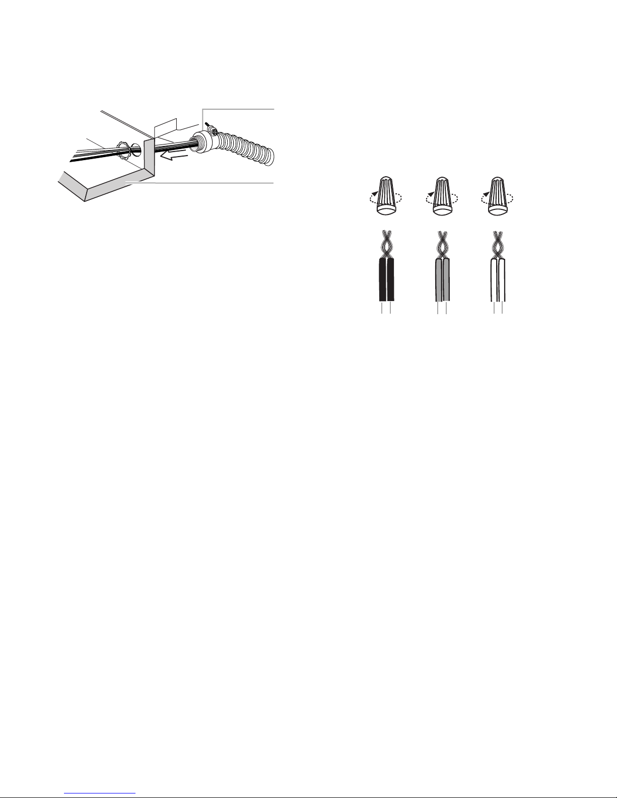
6. Install field-supplied conduit into the same
)
hole as the original bushing for the chassis
pigtail wires on the control box.
1
2
1. Field-supplied co nduit
2. Control box
7. Connect the chassis pigtail wires to the
incoming power supply wires using the UL
listed wire nuts (provided). Connect the
black wire to the incoming L1 (black) wire.
Connect the white wire to the incoming
neutral (white) wire. Connect the green
wire to the incoming ground (green or
bare) wire.
12 3
1. Black wire
2. Incoming L1 wire (black wire)
3. Green wire
4
4. Ground wire (green or bare wire
5. White wire
6. Neutral wire (white wire)
56
8. Reattach the PTAC/PTHP control panel
using the 4 screws removed earlier.
9. Reattach the PTAC/PTHP front cover using the thumbscrews removed earlier.
10. Reconnect power.
2-8
Page 17

REMOTE WALL THERMOSTAT INSTALLATION
INSTALLATION REQUIREMENTS
• Unpack and dispose of packaging materials.
• This thermostat is a wall mounted, low-voltage thermostat that maintains room temperature by controlling the operation of the
PTAC/PTHP. Batteries are not required—
temperature and mode settings are preserved with the power off.
• This is not a 2-stage heat pump thermostat
with emergency heat selection. The PTAC/
PTHP turns on the electric heat automatically based on the outdoor coil temperature,
which is influenced by the outdoor temperature and humidity conditions.
• Chassis must be installed before installing
remote thermostat.
IMPORTANT: Improper wiring or installation
may cause the thermostat not to function. Wiring must conform to local and national electrical codes.
LOCATION REQUIREMENTS
For best performance, thermostat should be
mounted:
• Approximately 5 ft (152.4 cm) from floor.
• Close to or in the room with the PTAC/PTHP,
preferably on an inside partitioning wall.
• On a section of wall without pipes or duct
work.
For best performance, do not mount thermostat:
• Close to a window, on an outside wall, or
next to a door leading to the outside.
• Exposed to direct light and heat from a lamp,
the sun, a fireplace, or other heat source.
This may cause a false reading.
• Close to or in direct airflow from the PTAC/
PTHP.
• In areas with poor air circulation (behind a
door or in an alcove).
Wall Thermostat Terminal Designation
Terminal Letter Operation Contact Made
Y Cooling During call for
cooling.
W Heating During call for heat-
ing.
G Fan Continuous if the
slider is in the “Fan”
position; otherwise,
on call for cooling or
heating.
C (common) Common Constant
Terminal
R 24 V to the Constant (directly
thermostat from the transformer)
B (Heat Pump Reversing Made continuously
units Only) Valve when the mode
switch is in heating.
INSTALL THE REMOTE WALL
THERMOSTAT
Replacing Existing Thermostat
1. Disconnect power to avoid product dam-
age during removal of existing thermostat.
2. Disconnect wires from existing thermo-
stat, one at a time. Do not allow wires to fall
back into the wall.
3. As each wire is disconnected, record wire
color and terminal marking.
4. Remove existing thermostat from wall.
5. See “Installing The New Thermostat.”
IMPORTANT: Mercury is a hazardous waste
and must be disposed of properly. Contact the
Thermostat Recycling Corporation at
www.nema.org/trc for further information, or
contact your local waste management authorities.
2-9
Page 18
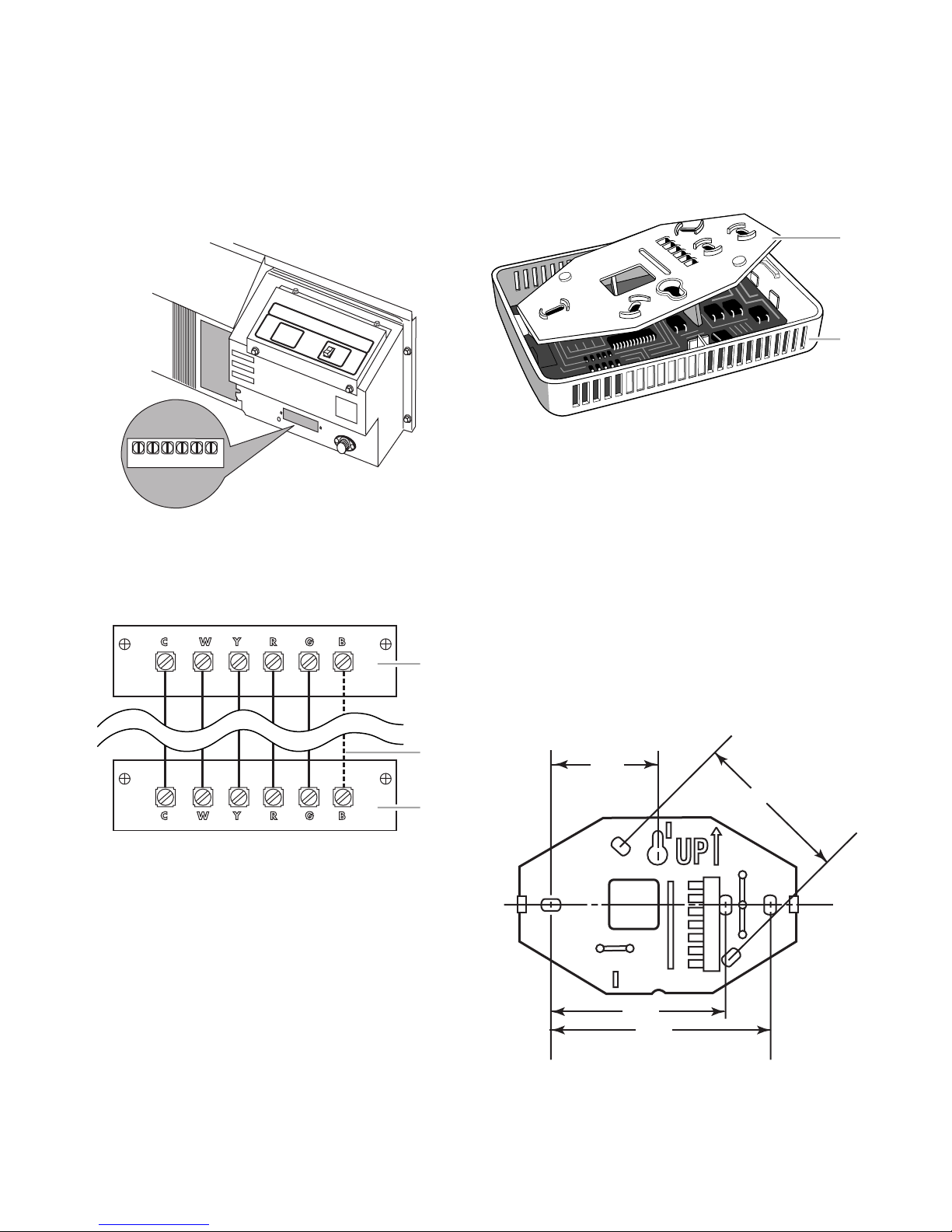
Installing The New Thermostat
1.587
2.375
2.625
3.275
1. Disconnect power to avoid product damage during installation of new thermostat.
2. Remove the PTAC/PTHP front cover.
3. Locate the terminal strip on the front of the
control box.
Remote Control UnitRemote Control Unit
5. Route the 24 volt thermostat wire alongside the conduit or service cord to the
location chosen for the thermostat.
6. Separate the front housing and back plate
of the thermostat.
1
OFF
ON
CWY RG B
4. Connect the field supplied 5 or 6 conductor, NEC Class 2, 24 volt thermostat wire
to the terminals in accordance with the
wiring diagram.
1
2
2
1. Back plate
2. Front housing
7. Route thermostat wires through hole in
back plate. Level back plate against wall
(for aesthetic value only—thermostat need
not be leveled for proper operation) and
mark wall through any 2 of the 6 available
mounting holes.
8. Drill two 3/18″ mounting holes in wall where
marked.
Optional Mounting Method: Mounting holes
on thermostat are designed to fit on a
horizontally-mounted junction box.
1. Typical PTAC/PTHP unit
2. Used for PTHP only
3. Wall thermostat
3
2-10
Page 19
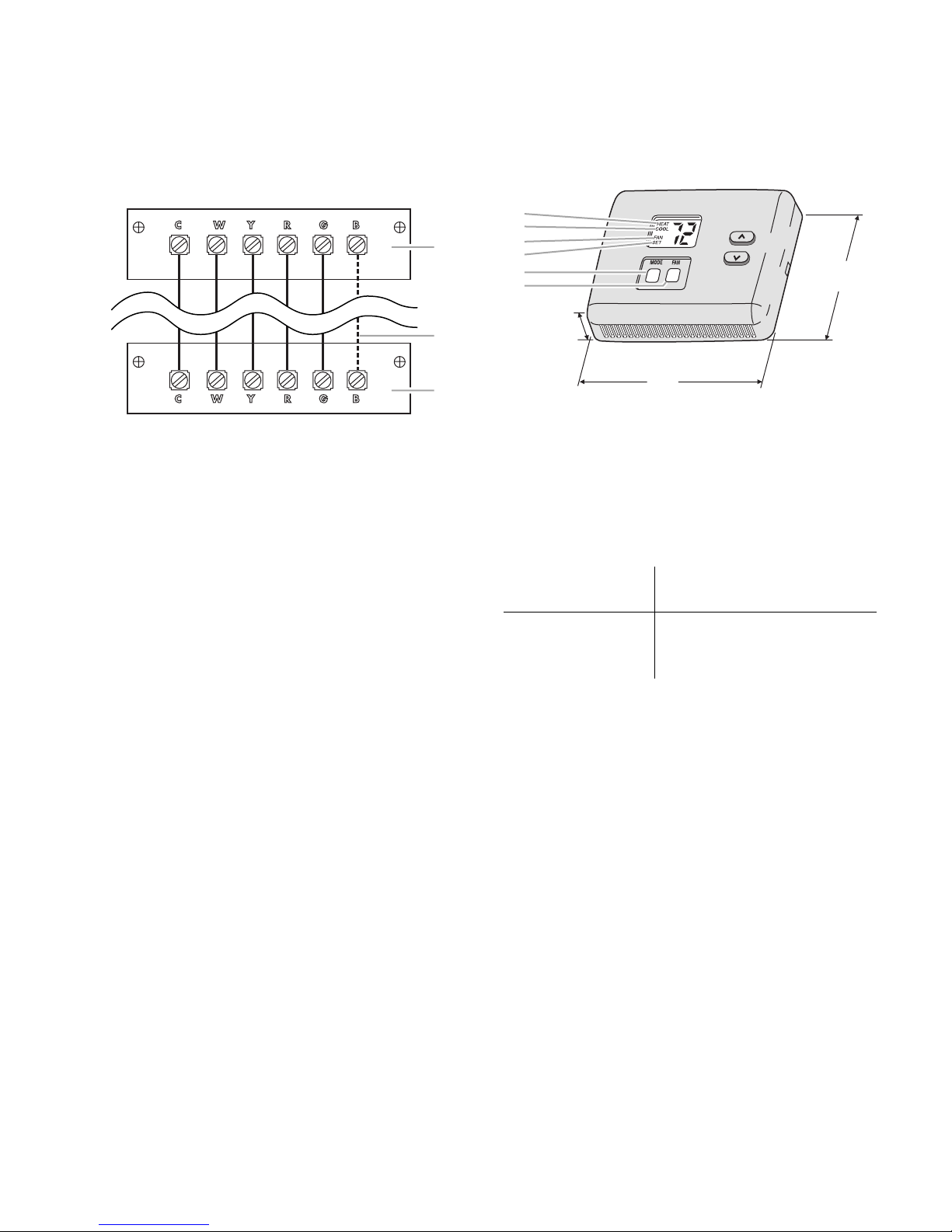
9. Secure back plate to wall with 2 anchors
and screws (provided) making sure all
wires extend through hole in back plate.
10. Connect wires to proper terminals of the
thermostat connector block.
1
2
14. Reconnect power.
NOTE: On power up, the LCD readout will display “oP” momentarily, and then the room temperature.
1
2
3
4
5
6
(20.3 mm)
0.8"
3.30"
(83.8 mm)
3
1. Typical PTAC/PTHP unit
2. Used for PTHP only
3. Wall thermostat
11. Push any excess wire back into wall. Excess wire inside the thermostat housing
can interfere with proper airflow across
the temperature sensor. Seal hole in wall
to prevent air leaks. Air leaks can affect
operation.
12. Install thermostat housing on back plate.
13. Reattach the PTAC/PTHP front cover.
4.55"
(115.6 mm)
1. Heat display
2. Cool display
3. Fan display
4. Set display
5. Mode button
6. Fan button
WHIRLPOOL DIGITAL
THERMOSTAT OPERATION
Error Messages
E4 Internal memory failure.
Replace thermostat.
- - (two dashes) Cannot read room temperature. Replace
thermostat.
Random Restart Feature
After a power outage, the Whirlpool digital thermostat will wait between 3 and 5 minutes before allowing the unit to restart. This is to keep
multiple units from restarting at the same time
when power is restored, thus preventing a circuit overload.
2-11
Page 20

— NOTES —
2-12
Page 21

PRODUCT OPERATION
THEORY OF OPERATION
Refrigeration Operation
The refrigeration system uses the following
four basic principles in its operation:
1. Heat always flows from a warmer body to
a cooler body.
2. Heat must be added to or removed from a
substance before a change in state can
occur.
3. Flow is always from a higher pressure
area to a lower pressure area.
4. The temperature at which a liquid or gas
changes state is dependent upon the pressure.
The refrigeration cycle begins at the compressor. Starting the compressor creates a low
pressure in the suction line which draws refrigerant gas (vapor) into the compressor. The
compressor then “compresses” this refrigerant, raising its pressure, and its temperature.
The refrigerant leaves the compressor through
the discharge line as a hot, high pressure gas.
The refrigerant enters the condenser coil where
it gives up some of its heat. The condenser fan
moves air across the finned surface of the
condenser coil, and facilitates the transfer of
heat from the refrigerant to the relatively cooler
outdoor air.
When a sufficient quantity of heat has been
removed from the refrigerant gas, the refrigerant will “condense” (change to a liquid). Once
the refrigerant has been condensed to a liquid,
it is further cooled by the air flowing across the
condenser coil.
The Packaged Terminal Air Conditioner (PTAC)
design determines at exactly what point (in the
condenser) the change of state (gas to liquid)
takes place. In all cases, however, the refrigerant must be totally evaporated (changed to a
gas) before leaving the evaporator coil.
Suction Line
Evaporator Coil
Capillary Tube
(Metering)
Refrigerant
Strainer
Discharge Line
Condenser Coil
Compressor
Liquid Line
Filter/Drier
3-1
Page 22
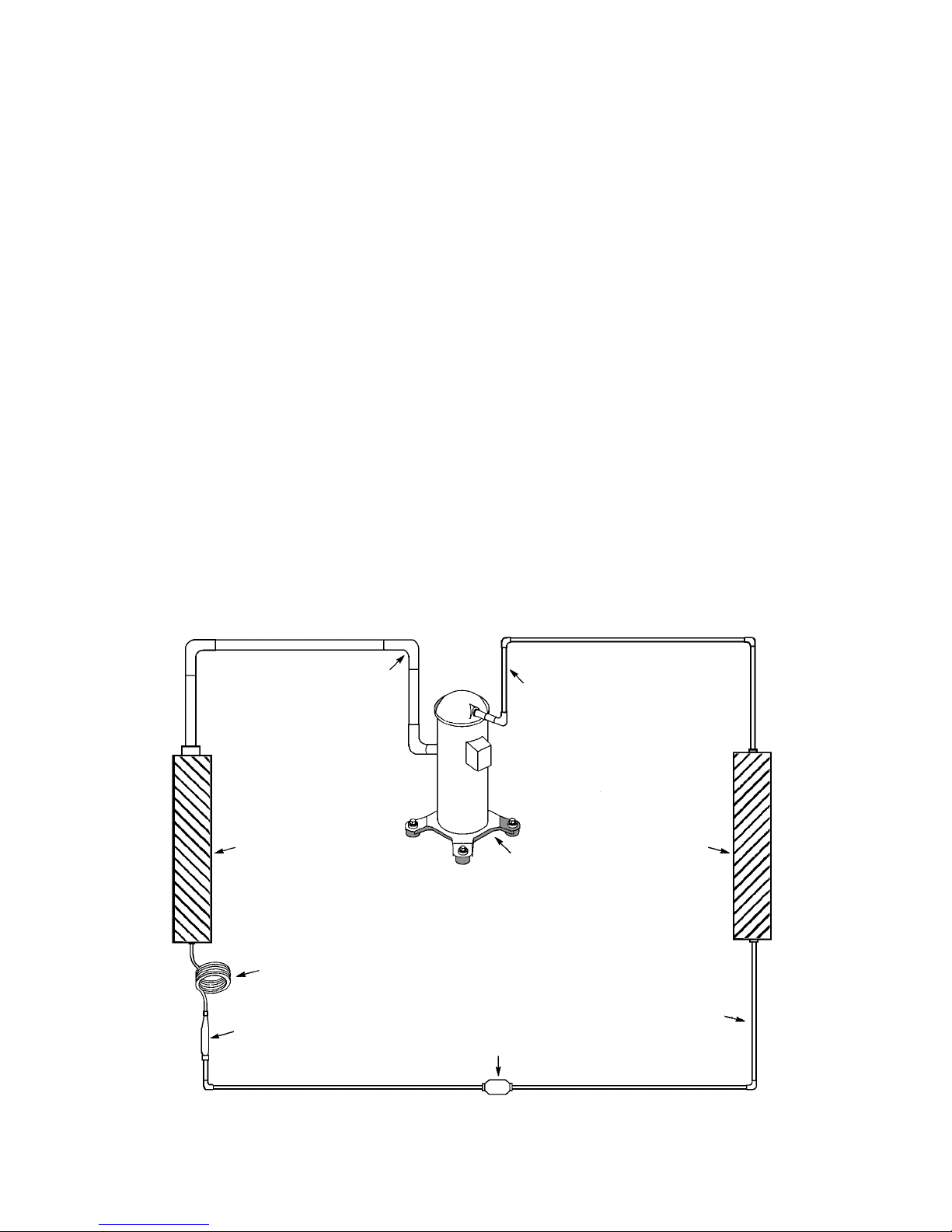
The refrigerant leaves the condenser coil as a
warm high pressure liquid. It then passes
through the filter/drier (if so equipped). It is the
function of the filter/drier to trap any moisture,
contaminants, and large particulate matter
present in the sealed system.
The liquid refrigerant next enters a metering
device called a “capillary tube” whose purpose
is to “meter” (control or measure) the quantity
of refrigerant entering the evaporator coil.
Since the blower is moving indoor air across
the finned surface of the evaporator coil, the
expanding refrigerant absorbs some of the
heat. This results in a lowering of the indoor air
temperature, hence the “cooling” effect.
The expansion and absorption of heat causes
the liquid refrigerant to evaporate, and change
back to a gas. Once the refrigerant has been
evaporated, it is further heated by the air that
continues to flow across the evaporator coil.
In the capillary tube, this is accomplished
through its size and length, and the pressure
difference present across the device.
Since the evaporator coil is under a lower
pressure than the liquid line, (due to the suction
created by the compressor), the liquid refrigerant leaves the capillary tube, and enters the
evaporator coil.
As the liquid enters the evaporator coil, the
larger area and lower pressure allows the
refrigerant to expand, and lower its temperature. This expansion is often referred to as
“boiling.”
Suction Line
The particular system design determines at
exactly what point the change of state, from a
liquid to a gas, takes place in the evaporator. In
all cases, however, the refrigerant must be
totally evaporated (changed to a gas) before
leaving the evaporator coil.
The low pressure (suction) created by the
compressor causes the refrigerant to leave the
evaporator through the suction line as a cool,
low pressure vapor. The refrigerant then returns to the compressor, where the cycle is
repeated.
Discharge Line
Evaporator Coil
Capillary Tube
(Metering)
Refrigerant
Strainer
Compressor
Condenser Coil
Liquid Line
Filter/Drier
3-2
Page 23
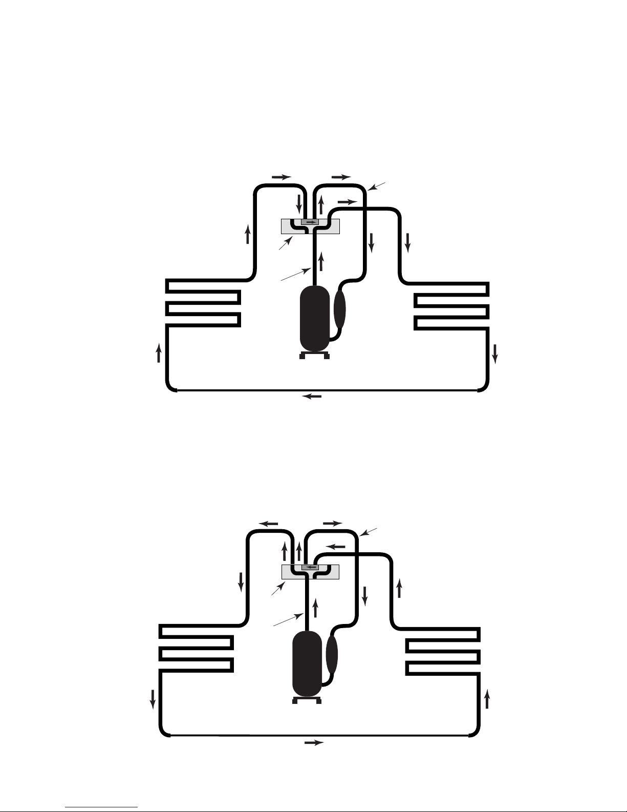
COOLING
Heat Pump Operation
All air conditioners are basically heat pumps.
They move, or “pump,” heat from inside a room
to the outdoors. A heat pump air conditioner
adds a component called a “reversing valve.” It
REVERSING
INSIDE COIL
VALV E
DISCHARGE
LINE
COMPRESSOR
allows heat to be transferred from the outdoors
into the room. When the reversing valve is not
energized, the system operates in the cooling
mode.
SUCTION LINE
OUTSIDE COIL
ACCUMULATOR
HEATING
When the reversing valve is energized, the
normal direction of refrigerant flow is diverted
at the valve. The outdoor coil now becomes the
low-pressure side of the system, and the inside
REVERSING
INSIDE COIL
VALV E
DISCHARGE
LINE
COMPRESSOR
coil becomes the high-pressure side. The flow
of all refrigerant past the reversing valve
changes direction, and now brings heat into the
room from the outdoors.
SUCTION LINE
OUTSIDE COIL
ACCUMULATOR
3-3
Page 24
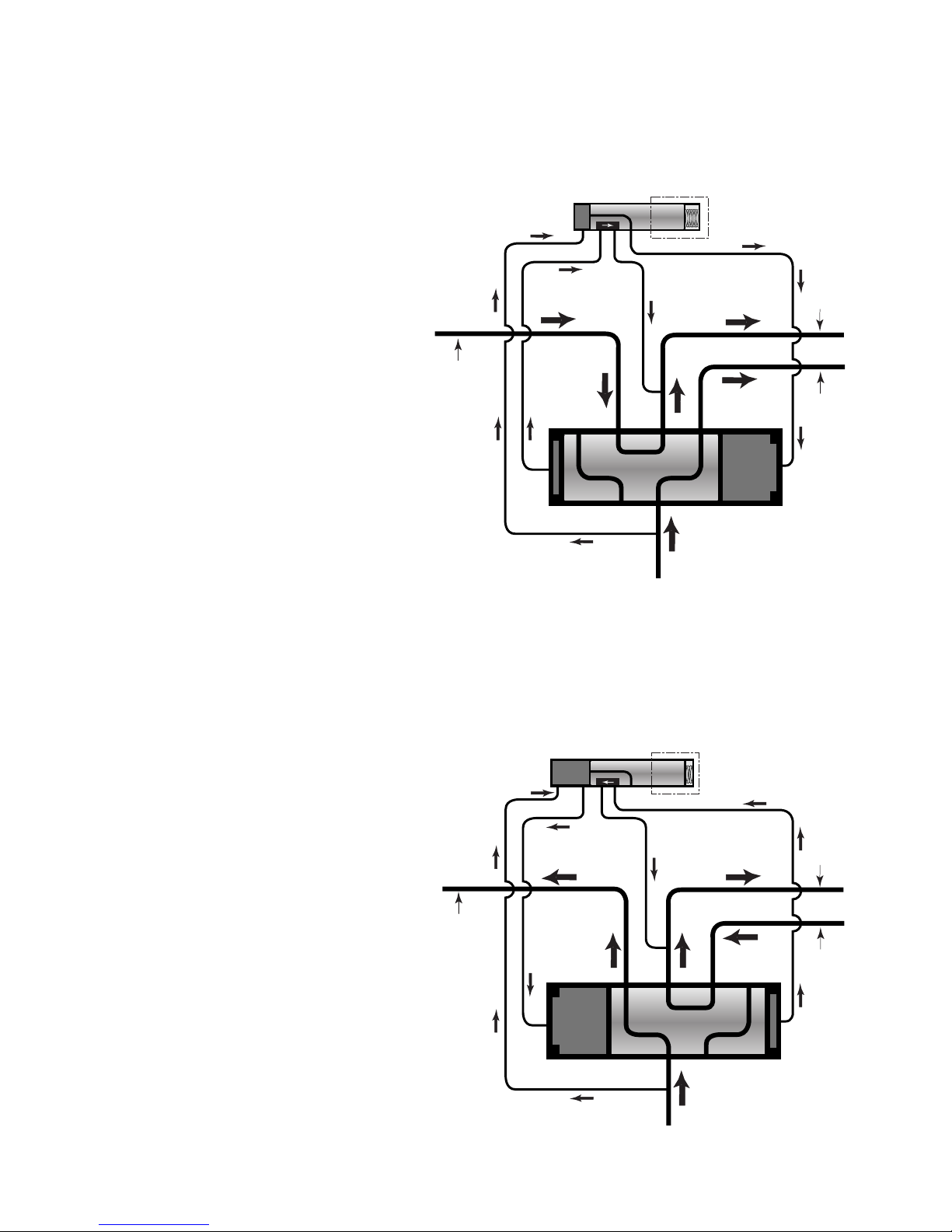
Reversing Valve Operation
PILOT VALVE SOLENOID
DE-ENERGIZED (COOLING)
The operation of the reversing valve is governed by the pilot solenoid coil. There are two
small lines going to the pilot valve, and two
lines going from the pilot valve to the main
valve body. With the solenoid de-energized,
the direction of flow is as shown, and the valve
is in the cooling mode.
TO EVAPORATOR
PILOT VALVE
(SOLENOID DE-ENERGIZED)
SUCTION LINE
TO CONDENSER
PILOT VALVE SOLENOID
ENERGIZED (HEATING)
When the solenoid is energized, refrigerant
flow from the suction and discharge lines is
redirected (reversed) through the pilot valve to
opposite ends of the main valve body. This
reverse in flow (pressure) causes the main
slide in the valve body to shift to the opposite
end, and reverses the flow of the entire system.
This reversed direction of refrigerant flow is
maintained as long as the pilot solenoid is
energized.
TO EVAPORATOR
DISCHARGE LINE
PILOT VALVE
(SOLENOID ENERGIZED)
SUCTION LINE
TO CONDENSER
DISCHARGE LINE
3-4
Page 25
Remote Thermostat Operation
ROOM THERMOSTATS
Room thermostats are controlled by the use of
a remote thermostat that will cycle the air
conditioner to maintain the desired room temperature.
The fan speed switch controls the high and low
fan speed operation. The switch is located on
the control panel, and is independent of the
thermostat.
Room thermostats range from the simple bimetallic type, to the more complex electronic
setback type. No matter how simple or complex, they are simply a switch (or series of
switches) designed to turn equipment on or off
under the desired conditions.
An improperly operating, or poorly located room
thermostat, can be the source of perceived
equipment problems. A careful check of the
thermostat and wiring must be made then to
insure that it is not the source of problems.
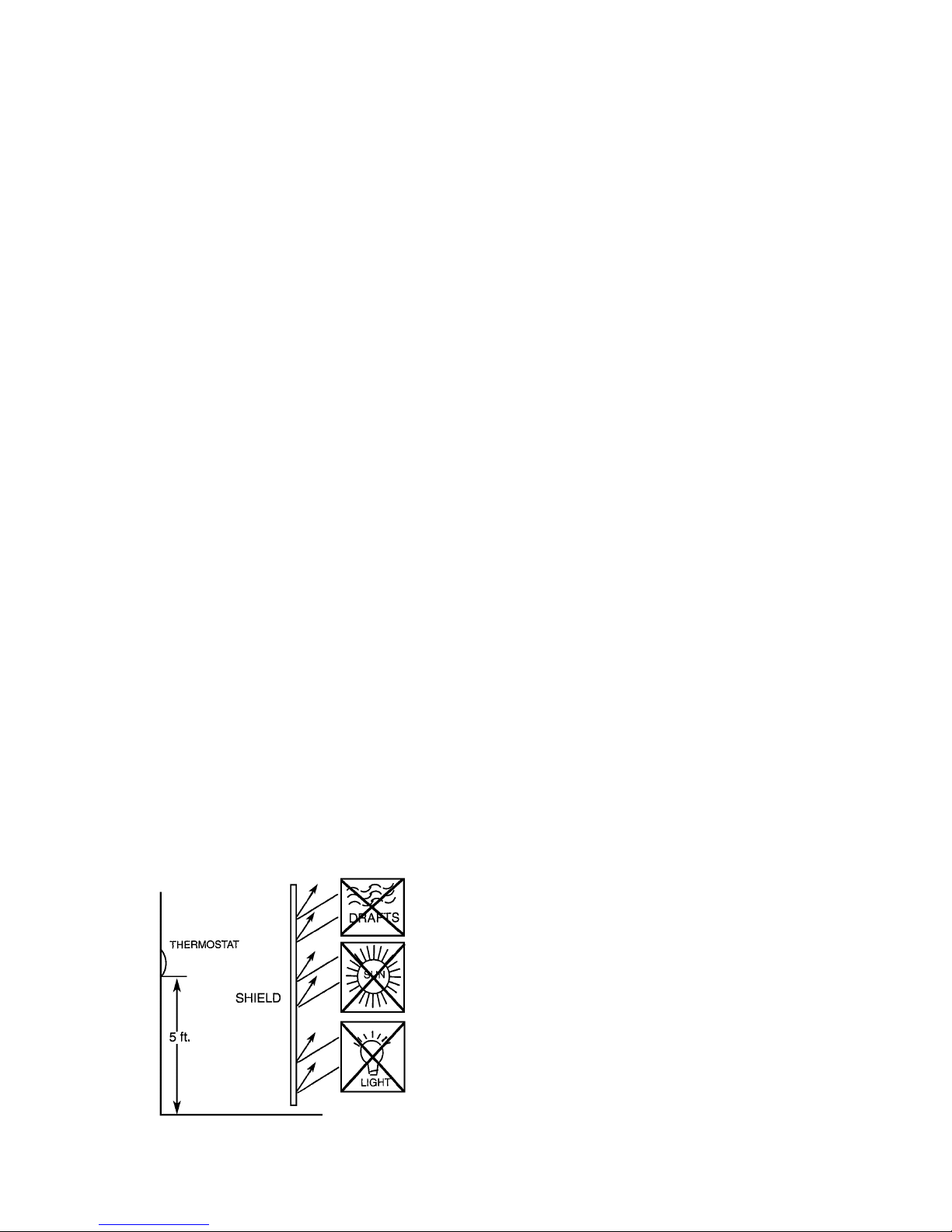
THERMOSTAT LOCATION
Thermostats should not be mounted where
they may be affected by drafts, discharge air
from registers, (hot or cold), or heat radiated
from the sun or appliances.
HEAT ANTICIPATORS
Heat anticipators are small resistance heaters
that are built into most electromechanical thermostats (wired in series with the control “W”
circuit). Their purpose is to prevent wide swings
in room temperature during system operation
in the “heating” mode. Since anticipators are
wired in series, the “W” section of the circuit will
open if one burns out, preventing the “heat”
operation.
The heat anticipator provides a small amount
of heat to the thermostat causing it to turn off
the heat source just prior to reaching the setpoint of the thermostat. This prevents exceeding the set point.
To accomplish this, the heat output from the
anticipator must be the same regardless of the
current flowing through it. Consequently, some
thermostats have an adjustment to compensate for varying current draw in the thermostat
circuits.
Electronic thermostats do not use a resistance-type anticipator. These thermostats use
a microprocessor that determines a cycle rate
based on a program loaded into it at the factory.
The thermostat should be located about 5′
above the floor, in an area of average temperature, with good air circulation. Close proximity
to the return air grille is the best choice.
Mercury bulb type thermostats must be level to
control temperature accurately to the desired
set-point.
3-5
Page 26

CALCULATING THE
APPROXIMATE CFM
The approximate CFM actually being delivered
can be calculated by using the following formula:
Kilowatts x 3413
Temperature Rise x 1.08
Do not use the kilowatt rating of the heater, as
this will result in an incorrect airflow calculation.
Kilowatts can be calculated by multiplying the
measured voltage to the unit, times the measured current draw of all the heaters that are in
operation to obtain the wattage (watts). Kilowatts are then obtained by dividing the watts by
1000.
EXAMPLE: The measured voltage to the unit is
230 volts. The measured current draw of the
heaters is 11.0 amps.
230 x 11.0 = 2530
2530 ÷ 1000 = 2.53 Kilowatts
2.53 x 3413 = 8635
Supply Air 95°F
Return Air 75°F
Temperature Rise 20°F
20 X 1.08 = 21.6
= CFM
8635
= 400 CFM
21.6
3-6
Page 27
Heat Pump Function
THE HOT START SENSOR
Under cold room conditions, (50°F, or below),
the Hot Start Sensor turns on the heater strips
with a call for heat to distribute warm air at the
beginning of the “Heat” cycle. Once the return
air has warmed sufficiently, (above 65°F), the
heat pump mode will begin.
THE HEAT PUMP
The heat pump uses backup electric resistance heating coils. At extremely low outdoor
ambient temperatures, the heat pump is automatically disabled, and the unit operates solely
on electric resistance heat.
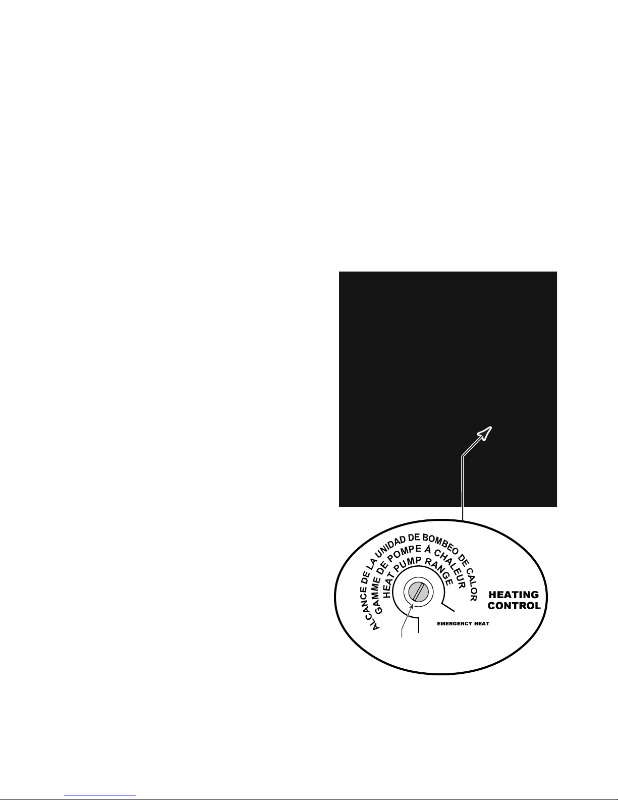
The heating control (defrost thermostat) is located behind the decorative front cover, and is
found on the right side panel of the chassis. Its
function is to allow the temperature range in
which the heat pump operates to be manually
adjusted.
Emergency Heat Operation Only: In the event
of a compressor malfunction in the “heat pump”
mode, turn the adjustment screw to the extreme counterclockwise “emergency heat” position. The heater will then cycle using electric
resistance heat only. Note that in the emergency heat position, the compressor is locked
out, disabling both the heat pump, and the
cooling operations. IMPORTANT: Do not forget to return the control to its original position
after repairs have been made. Otherwise, the
compressor will remain locked out, and will not
turn on during the “cooling” mode.
The heating control switches the unit’s heat
operation between the heat pump, and electric
resistance heat, based on the outdoor ambient
temperature. These change-over temperatures
are based on the settings of the control. The
factory set-point is at the one o’clock position.
If you wish to change the factory set-point,
insert a flat-bladed screwdriver into the slot and
turn counterclockwise to increase the changeover set-point, or clockwise to decrease it.
NOTE: Use the factory set-point for optimum
performance.
Adjustment
Screw
3-7
Page 28
OPERATING THE CONTROLS
TEMPERATURE CONTROL
The temperature control is a full range thermostat that maintains room temperature at the
desired setting for both heating and cooling.
Turn the knob counterclockwise for a warmer
temperature, and clockwise for a cooler temperature.
NOTE: Always rotate the temperature control
in small increments in the warmer or cooler
direction. Moving the control more than 1/4″ at
a time may overcompensate, and result in an
extreme hot or cold condition.
MODE (SYSTEM) SWITCH
Low and High Cool
This setting operates the unit in the “cooling”
mode. Cooling will not begin if the room temperature is below 60°F (15.5°C).
Low and High Heat
This setting operates the unit in the “heating”
mode.
Fan Only
This setting operates the fan continuously at
high fan speed to circulate air within the room.
No heating or cooling functions are active in
this mode.
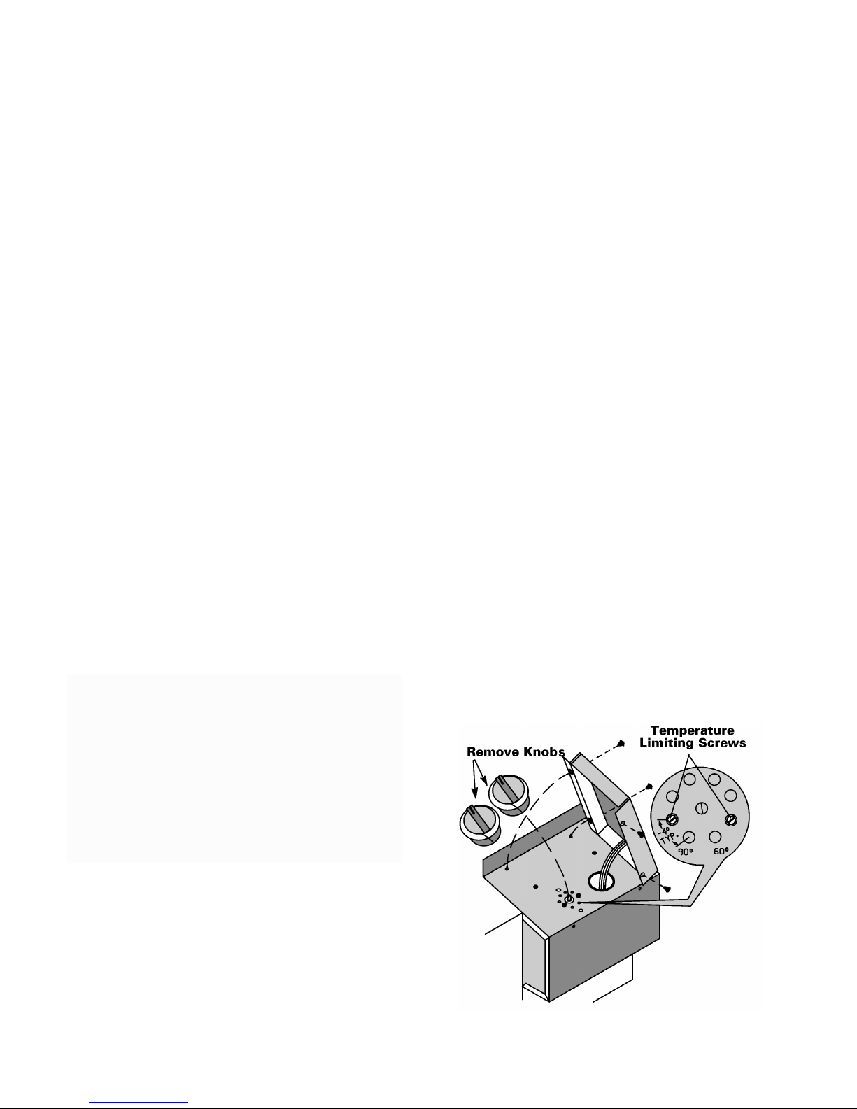
TEMPERATURE LIMITING
THERMOSTAT
The temperature limiting thermostat allows the
temperature range of the thermostat to be
varied.
To adjust the temperature range:
1. Turn the thermostat (temperature) control
to the center position.
2. Pull the two control knobs off the control
shafts and remove them.
3. Remove the four screws from the control
panel and rotate the panel up.
4. Note the location of the two temperature
limiting screws and remove the screws
from their present location. NOTE: The
screws are factory installed for a temperature range of between 60 and 90°F (15.5
to 32.2°C).
5. To adjust the temperature range, reinstall
the two screws at the desired hole locations. NOTE: Each hole represents an
approximate change of 4°. To set a maximum temperature range of approximately
64 to 86°F (17.7 to 30.0°C), install the two
screws at the hole locations shown in the
round illustration below.
6. Lower the control panel and install the two
screws, then reinstall the two control knobs.
3-8
Page 29
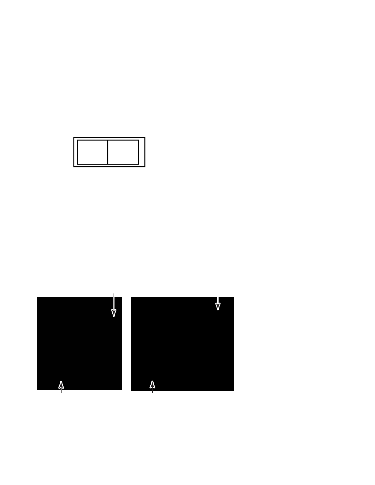
FAN CYCLE SWITCH
REMOTE THERMOSTAT
The fan cycle switch is located behind the
decorative front cover and below the control
box. The switch is designed to operate the fan
either continuously, or intermittently with the
compressor or heating elements. When the
switch is in the CONTINUOUS position, the fan
will run continuously when the unit is turned on.
With the switch in the CYCLE position, the fan
will run only when the compressor or heating
elements cycle on.
CONTINUOUS CYCLE
FRESH AIR VENT CONTROL
The fresh air vent control lever is located behind the front cover on the left side of the unit.
The unit is shipped in the Closed position with
a locking screw to prevent it from being moved.
Remove the screw to operate the control. When
the lever is back, the vent is open, and the
outside air is mixed with indoor air. When the
lever is forward, the vent is closed, and no
outside air is admitted into the room. Only room
air is recycled through the unit.
Remote thermostat units are controlled with a
remote thermostat that is usually mounted on
a wall. The thermostat will cycle the unit to
maintain the desired room temperature (see
page 3-5).
The fan speed switch controls the high and low
fan speed operation. The switch is located on
the control panel, and is independent of the
thermostat.
Vent Closed
Lever Forward
Lever Back
Vent Open
3-9
Page 30

— NOTES —
3-10
Page 31
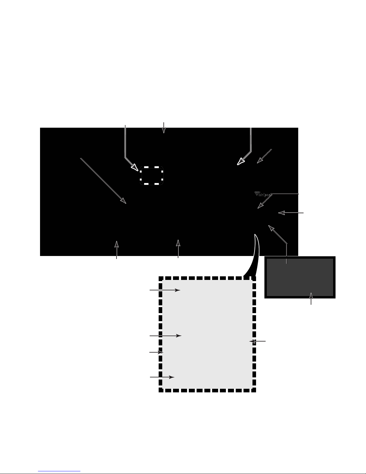
COMPONENT ACCESS
This section instructs you on how to service each component inside the Packaged Terminal Air
Conditioner. The components and their locations are shown below.
COMPONENT LOCATIONS
Heater & Limit Switch
Fan Motor
Evaporator
Hot Start Relay
Condenser
Sensing Bulb &
Heat Anticipator
Reversing Valve & Solenoid Coil
(Heat Pump Models Only)
Compressor &
Overload Protector
Indoor
Thermostat
Mode
(System)
Switch
Capacitor
Hot Start Sensor
Fan Cycle Switch
Not Shown: Condensate Valve Bellows
Remote Control Unit
Fan Switch
Defrost
Thermostat
Control Chassis Components
4-1
Page 32
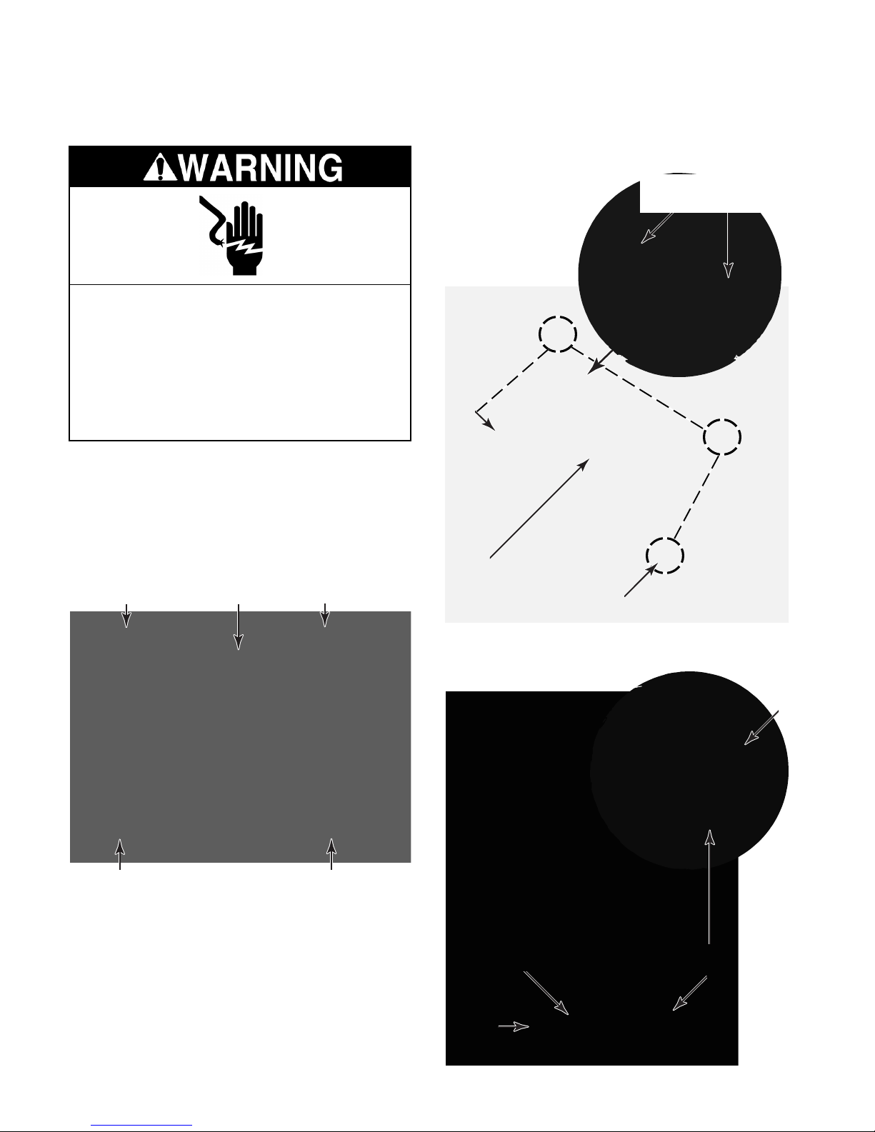
REMOVING THE INDOOR THERMOSTAT,
MODE (SYSTEM) SWITCH, AND HEAT ANTICIPATOR
Electrical Shock Hazard
Disconnect power before servicing.
Replace all parts and panels before
operating.
Failure to do so can result in death or
electrical shock.
1. Unplug air conditioner or disconnect power.
2. Remove the front cover from the unit (see
page 2-11 for the procedure).
6. Remove the four hex-head screws from
the control chassis.
Indoor Thermostat
Screws
3. Remove the four hex-head screws from
the control panel and lift the panel off the
unit.
Screw
Screw
Control Panel
Screw
Screw
Refer to the photos at the top of the right
column.
4. Pull the control knobs off the control shafts.
5. If you are replacing the indoor thermostat,
remove the two hex-head mounting
screws, as shown in the round inset.
Control Chassis
4 Control Chassis Screws
7. Rotate the top of the chassis down so that
you can access the components.
Locking
Tab
Mode
Indoor
Thermostat
Control
Chassis
Switch
4-2
Page 33
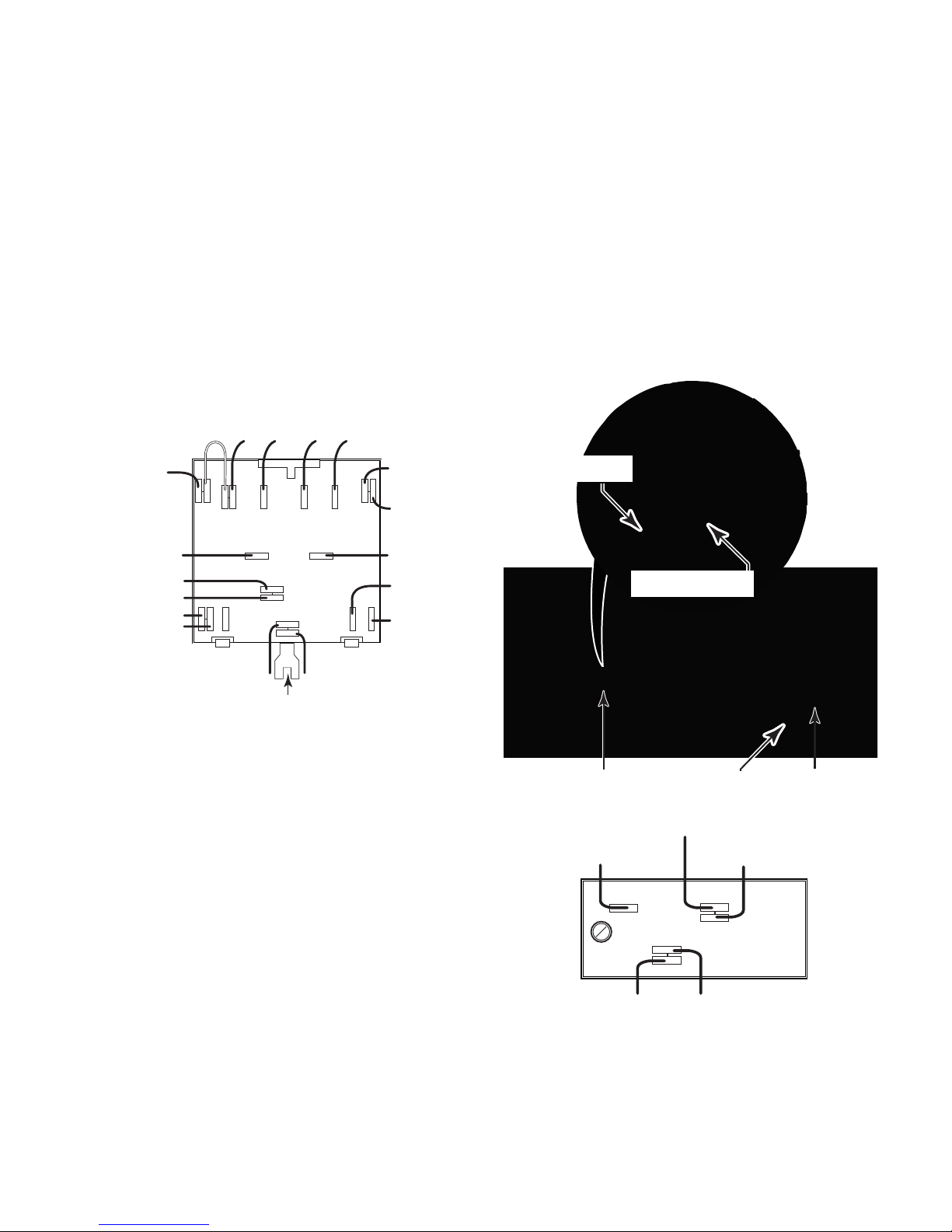
8. To remove the mode switch:
10. To remove the heat anticipator:
a) Raise the locking tab with a screwdriver
blade, rotate the switch body to the
right approximately 1/4-turn, and remove it from the chassis (see the round
inset photo in step 7).
b) Disconnect the wires from the switch
terminals. NOTE: Disconnect the wires
one at a time from the old switch, and
install each of them to the identical
terminals on the new one. This will help
prevent miswiring. The switch wiring is
shown below, and is also shown on the
Wiring Diagram supplied with the unit.
OR
(Heat Ant)
Ribbed
(Power Cd)
BK (Fan Cycle Sw)
BK (Thermostat)
RD (Rev. Valve)
RD (Hot Start Sensor)
BR
(Jumper)RD(Cap)
6
COM
Smooth
(Power)
L2
47
(Fan Mtr)RD(Fan Mtr)
L1
2
8
BK
HL
5
9
13
BU
(Hot Start Relay)
(Fan Cycle Sw)
BU
YL (Fan Cycle Sw)
BU
(Thermostat)
RD
(Thermostat)
a) Disconnect the orange wires from the
indoor thermostat and mode switch terminals.
b) Push the strain relief out of the control
chassis hole and remove it from the two
orange wires.
c) Pull the sensing bulb & heat anticipator
assembly off the front of the evaporator.
d) Pull the sensing tube out of the holder
and remove the heat anticipator.
Sensing Bulb
Heat Anticipator
BU (Temp Ctrl)
WH (Hot Start Relay)
Locking Tab
9. To remove the indoor thermostat:
a) Disconnect the wires from the indoor
thermostat terminals. NOTE: The wiring for the thermostat is shown to the
right, and also on the Wiring Diagram
supplied with the unit.
b) Pull the sensing bulb & heat anticipator
assembly off the front of the evaporator
(see the photos to the right).
c) Pull the sensing tube out of the holder
and through the grommet in the control
chassis, and remove the indoor thermostat.
Sensing Bulb & Heat
Anticipator Holder
BU (Mode Sw-Pin 3)
L3
OR (Heat Anticipator)
Strain ReliefGrommet
BK (Rev. Valve)
BK (Mode Sw-Pin 2)
C2
H1
RD (Mode Sw-Pin 1)
4-3
Page 34
REMOVING THE POWER SUPPLY CORD
Electrical Shock Hazard
Disconnect power before servicing.
Replace all parts and panels before
operating.
Ground
Screw
Strain Relief
Failure to do so can result in death or
electrical shock.
1. Unplug air conditioner or disconnect power.
2. Remove the front cover from the unit (see
page 2-11 for the procedure).
3. Lower the control chassis to access the
components (see page 4-2 for the procedure).
4. Disconnect the ribbed power supply cord
lead from mode switch terminal L2, and
the smooth lead from terminal L1 of the
mode switch.
5. Remove the machine screw from one end
of the green ground wire at the control
chassis, and the screw at the other end of
the green wire at the chassis location near
the capacitor.
6. Push the power cord strain relief out of the
control chassis mounting hole, and remove the power supply cord.
Power Cord
Leads (L1 & L2)
Ground Screw
Electrical Shock Hazard
Connect green ground wire to ground
screws.
Failure to do so can result in death or
electrical shock.
NOTE: Be sure to reinstall the power supply
cord leads to the mode switch terminals L1
(smooth) and L2 (ribbed), and the ends of the
green ground wire to the chassis locations with
their machine screws. Also, be sure to reinstall
the strain relief on the power supply cord.
4-4
Page 35
REMOVING THE DEFROST THERMOSTAT
4. Disconnect the wires from the defrost thermostat terminals.
5. Remove the two hex-head screws from
the defrost thermostat.
6. Remove the outdoor grille from the rear of
the unit.
Electrical Shock Hazard
Disconnect power before servicing.
Replace all parts and panels before
operating.
Failure to do so can result in death or
electrical shock.
1. Unplug air conditioner or disconnect power.
2. Remove the front cover from the unit (see
page 2-11 for the procedure).
3. Lower the control chassis to access the
components (see page 4-2 for the procedure).
7. Pull the sensing tube out of the condenser
and push the tube into the front of the unit
as far as possible.
Rear Of Unit
Sensing Tube
8. Pull the sensing tube inside and remove
the defrost thermostat.
Red Wire
Black Wire
2 Brown Wires
Defrost
Thermostat
Screws
Defrost Sensing Tube
Defrost Thermostat
4-5
Page 36
REMOVING THE HOT START RELAY
AND HOT START SENSOR
4. To remove the hot start relay:
a) Disconnect the wires from the relay
terminals.
b) Remove the two hex-head screws from
the relay and remove it.
WH
Electrical Shock Hazard
Disconnect power before servicing.
Replace all parts and panels before
operating.
Failure to do so can result in death or
electrical shock.
1. Unplug air conditioner or disconnect power.
2. Remove the front cover from the unit (see
page 2-11 for the procedure).
3. Lower the control chassis to access the
components (see page 4-2 for the procedure).
Hot Start Relay
BR-Defrost
Thermostat
RD
BU
BK
BR-Hot
Start
Sensor
5. To remove the hot start sensor:
a) Disconnect the wires from the sensor
terminals.
2 RD
Hot Start Sensor
BR
b) Remove the two hex-head screws from
the sensor and remove it.
Screw
Hot Start Sensor
Screw
4-6
Page 37
REMOVING THE CAPACITOR & FAN CYCLE SWITCH
Electrical Shock Hazard
Disconnect power before servicing.
Replace all parts and panels before
operating.
Failure to do so can result in death or
electrical shock.
1. Unplug air conditioner or disconnect power.
2. Remove the front cover from the unit (see
page 2-11 for the procedure).
3. Lower the control chassis to access the
components (see page 4-2 for the procedure).
BU
(White Ring)
Clamp
Screw
BR
(Green Ring)
2 RD & YL
(Black Ring)
Clamp
Screw
5. To remove the fan cycle switch:
a) Disconnect the wires from the switch
terminals.
b) Press in on the locking arms and push
the switch out of the control chassis
cutout.
REASSEMBLY NOTE: Make sure that you
position the fan cycle switch with the pin 1
terminal to the left as shown before you reinstall it in the chassis cutout.
Capacitor
Fan Cycle Switch
4. To remove the capacitor:
a) Disconnect the wires from the termi-
nals (see the illustrration at the top of
the right column).
b) Loosen the two hex-head screws from
the capacitor clamp and remove the
capacitor from the clamp.
4-7
Pin 1
BU
YL
VT & BK
Locking Arms
Page 38
REMOVING THE REMOTE CONTROL UNIT FAN SWITCH
4. Lift the remote control panel off the unit,
and turn it over.
5. Disconnect the wires from the fan switch
terminals.
6. Press in on the locking arms and push the
switch out of the control panel cutout.
Electrical Shock Hazard
Disconnect power before servicing.
Replace all parts and panels before
operating.
Failure to do so can result in death or
electrical shock.
1. Unplug air conditioner or disconnect power.
2. Remove the front cover from the unit (see
page 2-11 for the procedure).
3. Remove the four hex-head screws from
the remote control panel.
Screw Screw
Remote
Control Panel
Pin 1
BK
BU
RD
REASSEMBLY NOTE: Make sure that you
position the fan switch with the pin 1 terminal
positioned as shown before you reinstall it in
the control panel cutout.
Screw
Screw
4-8
Page 39
REMOVING THE HEATER & LIMIT SWITCH
Electrical Shock Hazard
Disconnect power before servicing.
Replace all parts and panels before
operating.
Failure to do so can result in death or
electrical shock.
1. Unplug air conditioner or disconnect power.
5. Remove the four hex-head screws from
the deck, then lift the left end of the deck,
pull the right end tabs out of their slots, and
remove the deck.
4 Screws
Deck
6. Lift the heater out of the unit and disconnect the two wires from the terminals.
7. To remove the limit switch from the heater,
remove the three screws.
2. Remove the front cover from the unit (see
page 2-11 for the procedure).
3. Remove the three hex-head screws from
the screen and remove the screen.
3 Screws
Screen
4. Remove the two hex-head screws from
the air deflector and remove the deflector.
Screw Screw
Air Deflector
Heater
Heater
Screw
Limit Switch
Screw
Screw
Wires
4-9
Page 40
REMOVING THE FAN MOTOR
Electrical Shock Hazard
Disconnect power before servicing.
Replace all parts and panels before
operating.
Failure to do so can result in death or
electrical shock.
1. Unplug air conditioner or disconnect power.
6. Disconnect the brown and yellow fan motor wires from the capacitor terminals.
BR Fan Mtr
(Green Ring)
YL Fan Mtr
(Black Ring)
2. Remove the unit from the wall sleeve (see
pages 2-10 and 2-11 for the procedure).
3. Remove the heater and limit switch from
the unit (see page 4-9 for the procedure).
4. Lower the control chassis so you can
access the fan motor wires (perform steps
3, 6, and 7 on page 4-2).
5. Disconnect the black and red fan motor
wires from mode switch terminals H and L.
7. Pull the ends of the four fan motor wires
through the chassis hole and remove them
from the plastic wire clamp.
Wire Clamp
Chassis Hole
BK
(Fan Mtr)
RD
(Fan Mtr)
Mode
Switch
4-10
COM
L1
L2
2
8
47
5
9
13
6
HL
Page 41
8. Using a 5/32″ allen wrench, loosen the
collar and clamp screws on the condenser
and evaporator fans.
10. Remove the two hex-head screws from
each of the condenser fan shroud mounting brackets and remove the brackets.
Collar Screw
Condenser
Fan
11. Remove the remaining three hex-head
screws from the condenser shroud (1 bottom and 2 side screws).
Condenser
Fan Shroud
Side Screw (1 of 2)
Brackets &
Screws (2 each)
Evaporator
Fan
Clamp Screw
9. Remove the four hex-head screws from
the bottom of the fan motor brackets (2 on
each bracket).
Bottom Screw
12. From the rear of the unit, pull the defrost
sensing tube out of the condenser and
from behind the bracket, and move it out of
the way.
13. Remove the two hex-head condenser
mounting screws from the chassis pan.
Sensor Tube
Bracket
Condenser
Screw
Screw
Fan Motor Bracket Screw (1 of 4)
Continued on the next page.
4-11
Page 42
14. Grasp the bottom of the condenser under
the two end brackets, and carefully lift the
assembly until the bottom of each bracket
is positioned over the top edge of the
chassis pan. Carefully pull the condenser
back just far enough to clear the fan motor
assembly when it is removed.
18. Remove the three 3/8″ hex-head screws
from the fan motor bracket and remove the
motor from the bracket.
Fan Motor
Screw (1 or 3)
Bracket
REASSEMBLY NOTES:
• When reinstalling the condenser fan, position the front edge of the blade so it is even
with the front edge of the shroud.
Position Condenser Brackets
Over Top Edge Of Chassis Pan
15. Pull the evaporator fan off the front shaft of
the fan motor.
NOTE: When you perform the following step,
be careful not to damage the thin metal vanes
of the condenser.
16. Lift the fan motor assembly and condenser
fan shroud, and pull the front motor shaft
out of the opening in the frame, then
remove the assembly from the unit.
17. Pull the condenser fan shroud and condenser fan off the motor.
Keep Blade Edge Even
With Edge Of Shroud
• When reinstalling the evaporator fan, make
sure that the front edge of the collar is even
with the front end of the motor shaft.
Keep Even
4-12
Page 43
REMOVING THE CONDENSATE VALVE BELLOWS
Electrical Shock Hazard
Disconnect power before servicing.
Replace all parts and panels before
operating.
Failure to do so can result in death or
electrical shock.
1. Unplug air conditioner or disconnect power.
2. Remove the unit from the wall sleeve (see
pages 2-10 and 2-11 for the procedure).
3. Remove the two hex-head screws from
each of the condenser fan shroud mounting brackets and remove the brackets.
5. Tilt the top of the condenser fan shroud
forward and pull the left end away from the
condenser just far enough to access the
condensate valve bellows.
Left Side View
Condenser Fan Shroud
4. Remove the remaining three hex-head
screws from the condenser shroud (1 bottom and 2 side screws).
Condenser
Fan Shroud
Shroud Brackets &
Screws (2 each)
Side Screw (1 of 2)
Remove Nut
Condensate Valve Bellows
(Front View)
Loosen Nut
6. Remove the left 5/16″ nylon mounting nut
on the condensate valve bellows, and
loosen the right nut approximately half
way on the chassis pan stud.
Bottom Screw
4-13
Page 44
REMOVING THE OVERLOAD PROTECTOR
AND THE COMPRESSOR
Electrical Shock Hazard
Disconnect power before servicing.
b) Disconnect the black wire from the com-
pressor terminal, and the black wire
from the overload protector terminal.
Black
Wires
Replace all parts and panels before
operating.
Failure to do so can result in death or
electrical shock.
1. Unplug air conditioner or disconnect power.
2. Remove the unit from the wall sleeve (see
pages 2-10 and 2-11 for the procedure).
3. To remove the overload protector:
a) Remove the hex cap nut and the nylon
flat washer from the terminal cover and
remove the cover.
Hex Cap Nut
& Nylon Flat
Washer
Compressor
Terminals
Overload
Protector
REASSEMBLY NOTE: When you reinstall the
terminal cover on the compressor, make sure
that the overload protector is centered in the
gasket hole, and does not sit on any portion of
the gasket.
4. To remove the compressor:
a) Remove the overload protector (see
step 3).
b) Disconnect the blue wire from the S (V)
terminal and the red wire from the R (U)
terminal of the compressor.
c) Remove the gasket.
Terminal
Cover
4-14
Red
Wire
Blue
Wire
Gasket
Page 45
d) Braze on an access valve and dis-
charge the sealed system refrigerant
into an approved recovery system.
e) Disconnect the high side line from the
compressor, and the suction line from
the accumulator.
g) Lift the compressor from the unit and
remove the three rubber shock mounts.
Suction Line
To Accumulator
High Side Line
To Compressor
f) Remove the three 1/2″ hex bolts from
the compressor’s rubber shock mounts.
Rubber Shock
Mount (1 of 3)
1/2″ Hex Bolt
4-15
Page 46
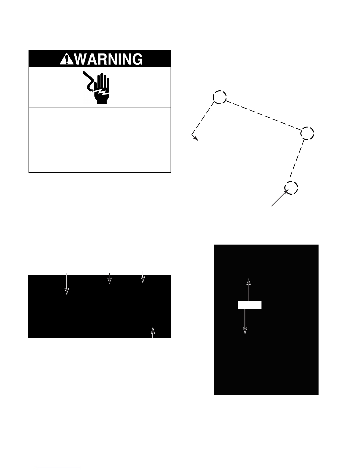
REMOVING THE EVAPORATOR
Electrical Shock Hazard
Disconnect power before servicing.
Replace all parts and panels before
operating.
Failure to do so can result in death or
electrical shock.
1. Unplug air conditioner or disconnect power.
2. Remove the unit from the wall sleeve (see
pages 2-10 and 2-11 for the procedure).
3. Braze on an access valve and discharge
the sealed system refrigerant into an approved recovery system.
4. Remove the screen, air deflector, and
deck from the front of the unit (see steps 3,
4, and 5 on page 4-9).
5. Remove the four hex-head screws from
the control chassis, and rotate the chassis
down.
4 Control Chassis Screws
6. Remove the two hex-head screws from
the evaporator mounting plate, located on
the right side of the chassis.
Deck
Air Deflector
Screen
Screws
Evaporator
Mounting Plate
4-16
Page 47
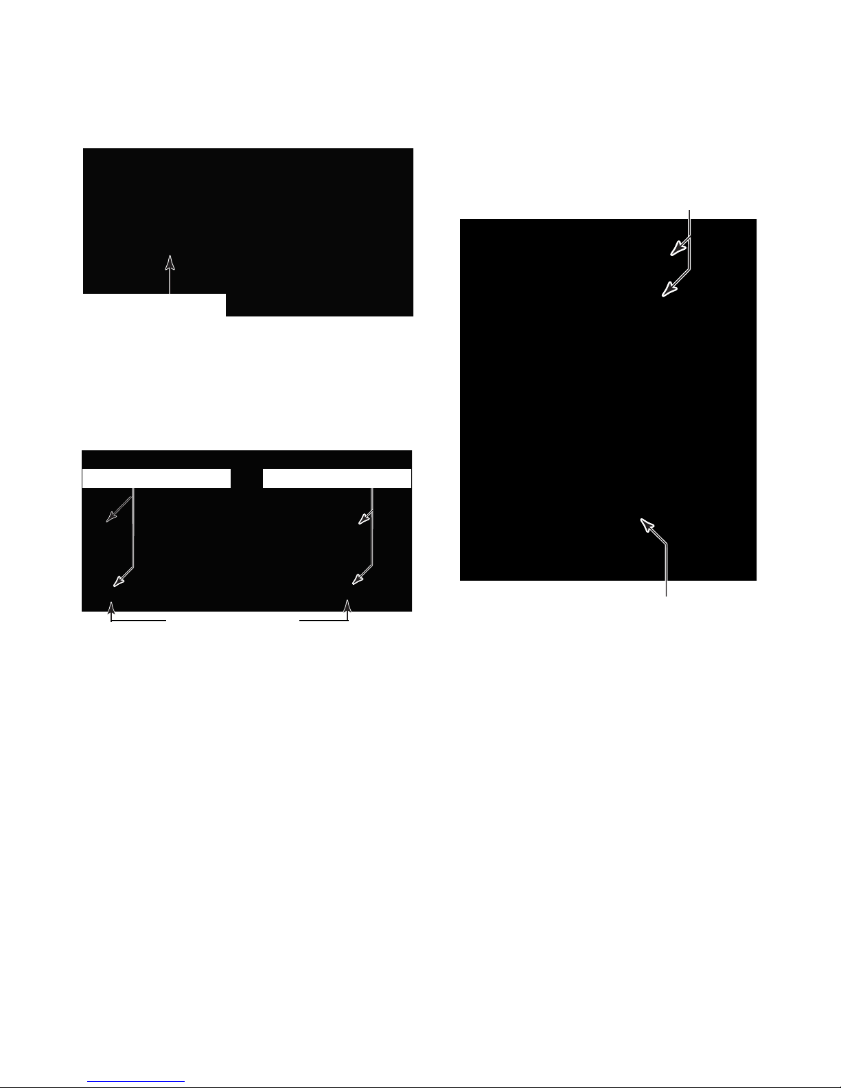
7. Pull the indoor thermostat sensing bulb
and heat anticipator off the evaporator
and position it out of the way.
Sensing Bulb & Heat
Anticipator Holder
8. Remove the six front evaporator mounting
screws (two from the chassis flange, two
from the mounting plate, and two from the
chassis pan). Remove the mounting plate
from the unit.
9. Lift the evaporator just enough to position
it away from the styrofoam holder, and
install heat insulation below it.
10. Unbraze the tubing joints at the top and
bottom of the evaporator.
Unbraze Tubing Joints
Chassis Flange Screws
Chassis Pan Screws
Mounting Plate Screws
Unbraze Tubing Joint
11. After the evaporator cools, remove it from
the unit.
4-17
Page 48
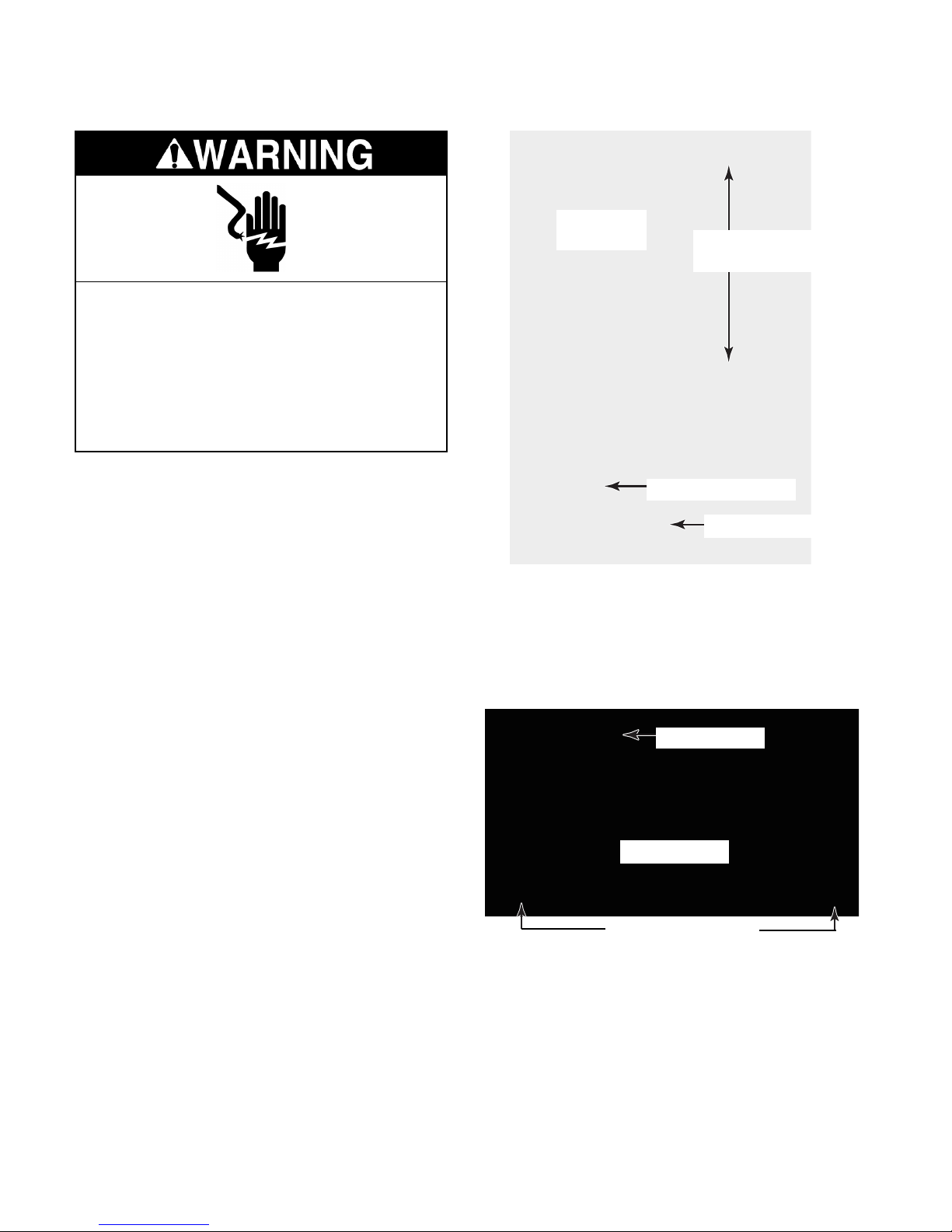
REMOVING THE CONDENSER
Electrical Shock Hazard
Disconnect power before servicing.
Replace all parts and panels before
operating.
Failure to do so can result in death or
electrical shock.
Condenser
Fan Shroud
Shroud Brackets &
Screws (2 each)
1. Unplug air conditioner or disconnect power.
2. Remove the unit from the wall sleeve (see
pages 2-10 and 2-11 for the procedure).
3. Braze on an access valve and discharge
the sealed system refrigerant into an approved recovery system.
4. Remove the two hex-head screws from
each of the condenser fan shroud mounting brackets and remove the brackets
(see the photo at the top of the right
column).
5. Remove the remaining three hex-head
screws from the condenser shroud (1 bottom and 2 side screws).
6. Tilt the top of the condenser fan shroud
forward and pull it away from the condenser just far enough to protect it from
the brazing heat.
Side Screw (1 of 2)
Bottom Screw
7. Pull the defrost thermostat sensing bulb
from the condenser and move it out of the
way.
8. Remove the two condenser hex-head
screws from the chassis pan.
Sensing Bulb
Condenser
Chassis Pan Screws
4-18
Page 49
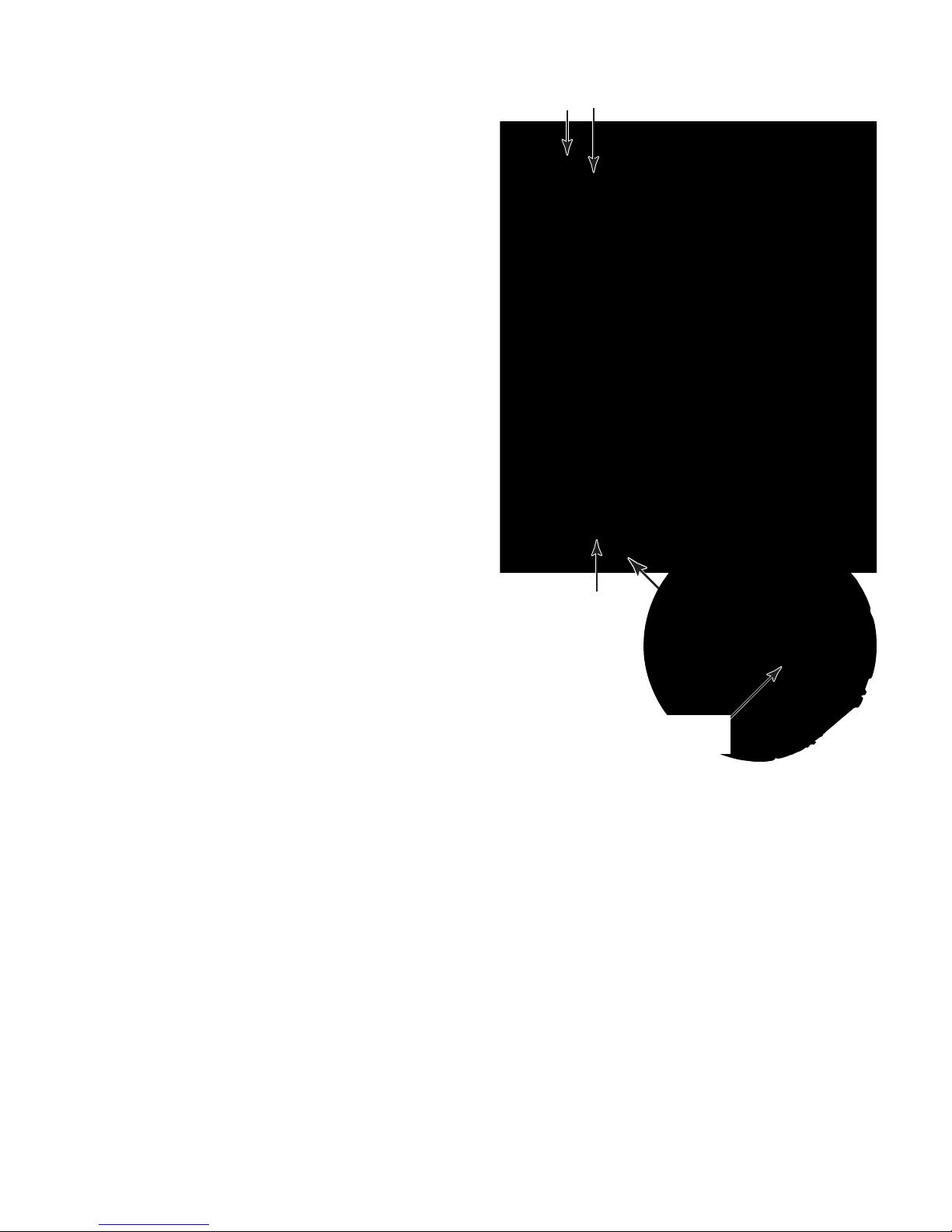
9. Grasp the bottom of the condenser under
the two end brackets, and carefully lift the
assembly until the bottom of each bracket
is positioned over the top edge of the
chassis pan. Carefully pull the condenser
back just far enough to clear the fan motor
assembly when it is removed.
10. Unbraze the three tubing joints (two at the
top and one at the bottom) and remove
them from the condenser.
11. Remove the condenser from the unit.
Unbraze Tubing Joints
Unbraze
Tubing Joint
Position Condenser Brackets
Over Top Edge Of Chassis Pan
4-19
Page 50
REMOVING THE SOLENOID COIL & REVERSING VALVE
Coil Wires
Electrical Shock Hazard
Disconnect power before servicing.
Replace all parts and panels before
operating.
Failure to do so can result in death or
electrical shock.
1. Unplug air conditioner or disconnect power.
2. Remove the unit from the wall sleeve (see
pages 2-10 and 2-11 for the procedure).
3. Braze on an access valve and discharge
the sealed system refrigerant into an approved recovery system.
5. To remove the reversing valve and so-
lenoid:
a) Remove the solenoid coil (see step 4).
b) Unbraze the four tubing joints from the
c) Apply thermal heat trap material around
Solenoid Coil
reversing valve.
the new solenoid and valve to protect
them.
Screw
Reversing Valve & Solenoid Coil
4. To remove the solenoid coil (see the
photo at the top of the right column):
a) Disconnect the two wire connectors
from the coil terminals.
b) Remove the hex-head screw.
c) Slide the coil off the valve.
Solenoid
4 Tubing Joints
Reversing Valve
4-20
Page 51
COMPONENT TESTING
Before testing any of the components, perform
the following checks:
• Control failure can be the result of corrosion
on connectors. Therefore, disconnecting and
reconnecting wires will be necessary throughout test procedures.
• All tests/checks should be made with a VOM
or DVM having a sensitivity of 20,000 ohmsper-volt DC, or greater.
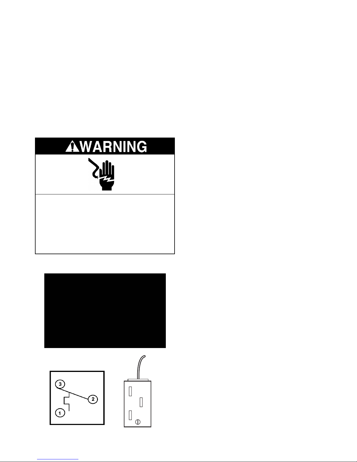
Electrical Shock Hazard
Disconnect power before servicing.
Replace all parts and panels before
operating.
Failure to do so can result in death or
electrical shock.
INDOOR THERMOSTAT
• Check all connections before replacing components, looking for broken or loose wires,
failed terminals, or wires not pressed into
connectors far enough.
• Resistance checks must be made with power
cord unplugged from outlet, and with wiring
harness or connectors disconnected.
Refer to page 4-2 for the procedure for servicing the indoor thermostat.
NOTE: The temperature should be above 60°F
(15.5°C) to determine the following readings.
1. Unplug air conditioner or disconnect power.
2. Disconnect the wires from the thermostat
terminals.
3. Set the ohmmeter to the R x 1 scale.
4. Clip the black (–) ohmmeter test lead to
terminal 2 (common) and leave it there.
5. Rotate the temperature control fully coun-
terclockwise (Warmer).
6. Touch the positive (+) ohmmeter test lead
to terminal 1. The meter should indicate a
closed (0 Ω) circuit.
7. Touch the positive (+) ohmmeter test lead
to terminal 3 (L3). The meter should indicate an open (infinite) circuit.
8. Rotate the temperature control fully clock-
wise (Cooler).
9. Touch the positive (+) ohmmeter test lead
to terminal 1. The meter should indicate an
open (infinite) circuit.
10. Touch the positive (+) ohmmeter test lead
to terminal 3 (L3). The meter should indicate a closed (0 Ω) circuit.
1
2
3
5-1
Page 52
Electrical Shock Hazard
Disconnect power before servicing.
Replace all parts and panels before operating.
Failure to do so can result in death or electrical shock.
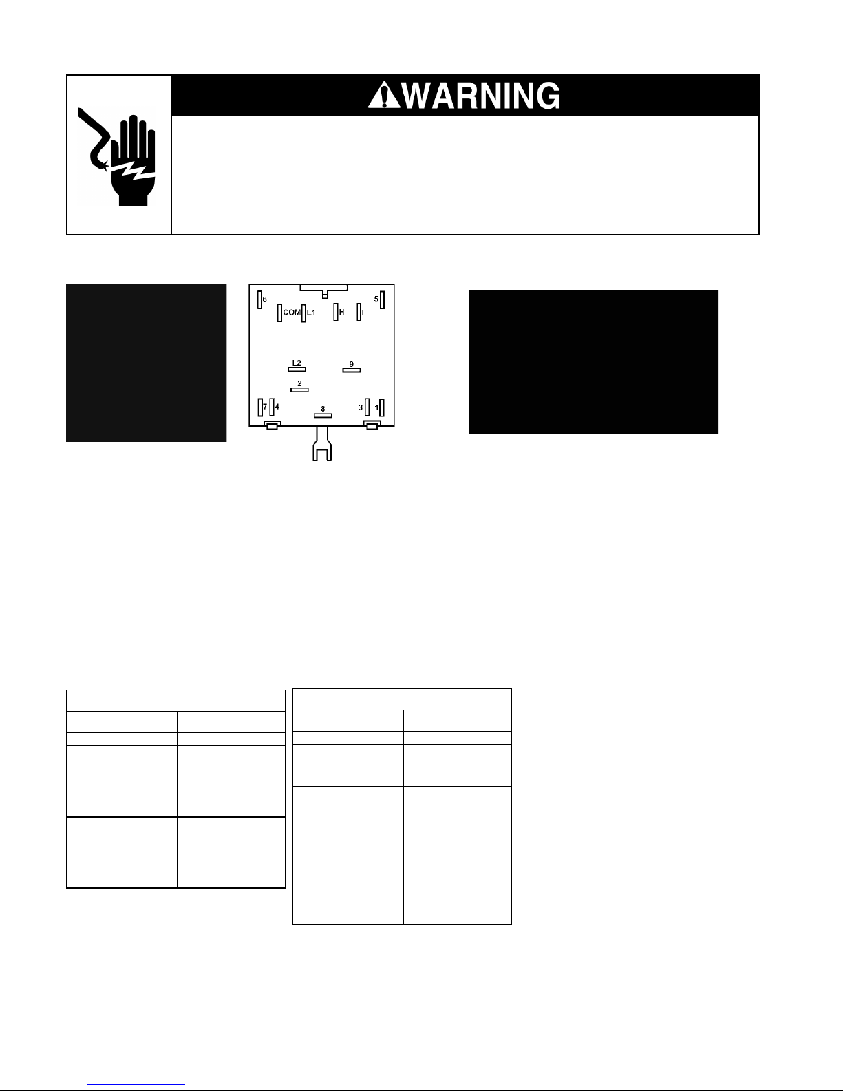
MODE (SYSTEM) SWITCH HEAT ANTICIPATOR
Refer to page 4-2 for the procedure for servic-
Refer to page 4-2 for the procedure for servicing the mode (system) switch.
ing the heat anticipator.
1. Unplug air conditioner or disconnect power.
1. Unplug air conditioner or disconnect power.
2. Disconnect the wires from the mode switch
terminals.
3. Set the ohmmeter to the R x 1 scale.
4. To check the switch contact operation,
touch the ohmmeter test leads to the switch
terminals shown in the following charts:
SWITCH CONTINUITY
SWITCH POSITION CONTACTS MADE
OFF NONE
L1 - 2
LOW COOL
HIGH COOL
5 - 3
4 - 6
L - 9
COM - L2
L1 - 2
5 - 3
4 - 6
H - 9
COM - L2
SWITCH POSITION CONTACTS MADE
SWITCH CONTINUITY
OFF NONE
FAN ONLY
HIGH HEAT
LOW HEAT
2. Disconnect the heat anticipator wires from
the mode switch terminals.
3. Set the ohmmeter to the R x 10K scale.
4. Touch the ohmmeter test leads to the
ends of the orange heat anticipator wires.
The meter should indicate approximately
56 K Ω .
8 - H
COM - L2
L1 - 8
L1 - 2
5 - 1
7 - 6
H - 9
COM - L2
L1 - 2
5 - 1
7 - 6
L - 9
COM - L2
5-2
Page 53
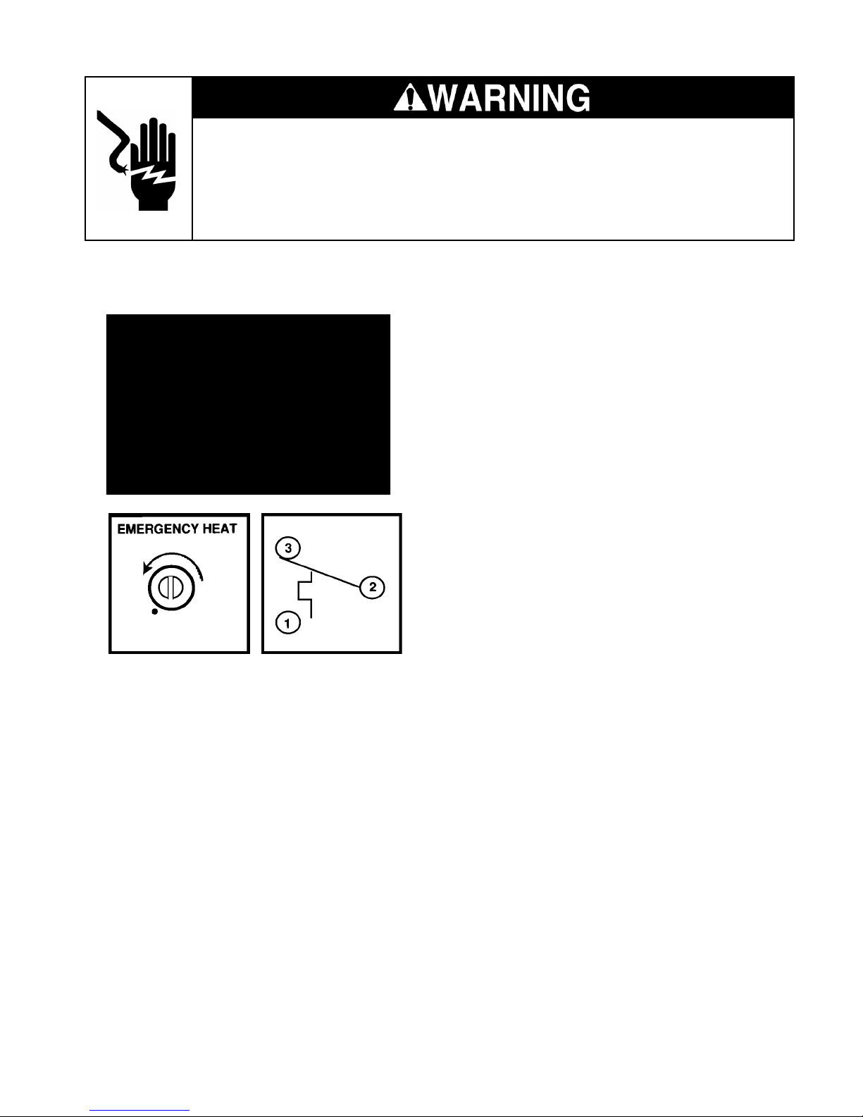
Electrical Shock Hazard
Disconnect power before servicing.
Replace all parts and panels before operating.
Failure to do so can result in death or electrical shock.
DEFROST THERMOSTAT
(EMERGENCY HEAT SWITCH)
1. Unplug air conditioner or disconnect power.
2. Disconnect the wires from the thermostat
terminals.
3. Turn the screwdriver control to the fully
counterclockwise (emergency heat) position.
4. Set the ohmmeter to the R x 1 scale.
5. Clip the black (–) ohmmeter test lead to
terminal 2 (C2) and leave it there.
6. Touch the positive (+) ohmmeter test lead
to terminal 1 (H1). The meter should indicate a closed (0 Ω) circuit.
7. Touch the positive (+) ohmmeter test lead
to terminal 3 (L3). The meter should indicate an open (infinite) circuit.
8. Rotate the screwdriver control clockwise.
When the control reaches its setpoint, the
meter should indicate a closed (0 Ω) circuit.
Refer to page 4-5 for the procedure for servicing the defrost thermostat.
NOTE: Continuity will be read between terminals 2 and 3, providing the temperature of the
capillary tube is above 25°F (–4°C). If the
temperature at the capillary tube is above 52°F
(11°C), it may be necessary to place the end of
the capillary tube in ice water to determine if the
control is sensing temperature changes.
5-3
Page 54
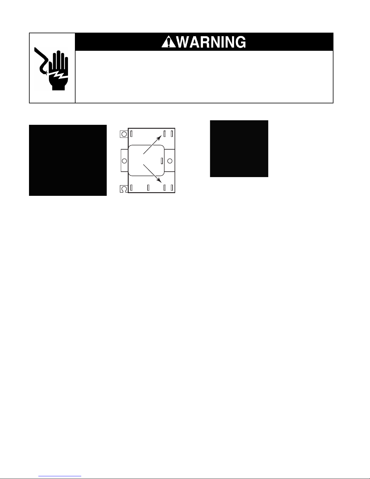
Electrical Shock Hazard
Disconnect power before servicing.
Replace all parts and panels before operating.
Failure to do so can result in death or electrical shock.
HOT START RELAY HOT START SENSOR
3
COIL
5
Closed Below 50°F
Open above 65°F
14
Refer to page 4-6 for the procedure for servicing the hot start relay.
1. Unplug air conditioner or disconnect power.
2. Disconnect the wires from the relay terminals.
3. Set the ohmmeter to the R x 1 scale.
4. Touch the ohmmeter test leads to the
following relay terminals:
1 to 3 = open (infinite) circuit
4 to 5 = closed (0 Ω) circuit
5. Set the ohmmeter to the R x 100 scale.
6. Touch the ohmmeter test leads to the coil
(unmarked) terminals. The meter should
indicate between 1480 and 1520 Ω.
Refer to page 4-6 for the procedure for servicing the hot start sensor.
1. Unplug air conditioner or disconnect power.
2. Disconnect the wires from the sensor terminals.
3. Set the ohmmeter to the R x 1 scale.
4. Touch the ohmmeter test leads to the
sensor terminals. The meter should indicate an open (infinite) circuit at room temperatures above 65°F.
5-4
Page 55
Electrical Shock Hazard
Disconnect power before servicing.
Replace all parts and panels before operating.
Failure to do so can result in death or electrical shock.
CAPACITOR
Refer to page 4-7 for the procedure for servicing the capacitor.
1. Unplug air conditioner or disconnect power.
2. Disconnect the wires from the capacitor
terminals.
3. Set the ohmmeter to the R x 1K scale.
4. Touch one of the ohmmeter test leads to
the common (C) terminal and the other
test lead to the FAN and HERM terminals.
5. The meter should indicate several ohms
and gradually return to infinity at both the
FAN & HERM terminals.
FAN CYCLE SWITCH & REMOTE
CONTROL UNIT FAN SWITCH
Refer to page 4-7 for the procedure for servicing the fan cycle switch, and page 4-8 for the
remote control unit fan switch.
1. Unplug air conditioner or disconnect power.
2. Disconnect the wires from the switch terminals.
3. Set the ohmmeter to the R x 1 scale.
4. Clip one of the ohmmeter test leads to the
center (common) terminal and leave it
there.
5. Touch the ohmmeter test leads to pins 1
and 3. Depending on the position of the
rocker pushbutton, the meter should indicate an open (infinite) circuit at one pin,
and a closed (0 Ω) circuit at the other pin.
6. Press the rocker pushbutton to the other
switch position, and repeat step 5. The
meter readings should be reversed.
5-5
Page 56
Electrical Shock Hazard
Disconnect power before servicing.
Replace all parts and panels before operating.
Failure to do so can result in death or electrical shock.
HEATER & LIMIT SWITCH (N.C.)
Limit Switch
Heater
Refer to page 4-9 for the procedure for servicing the heater and limit switch.
1. Unplug air conditioner or disconnect power.
2. Disconnect the heater wire from the hot
start sensor terminal.
FAN MOTOR
Refer to page 4-10 for the procedure for servicing the fan motor.
1. Unplug air conditioner or disconnect power.
2. Set the ohmmeter to the R x 1 scale.
3. Touch the ohmmeter test leads to the
following motor wire connectors. Disconnect one of the wires before you make the
measurement:
Black to red = 100 to 110 Ω
Yellow to brown = 180 to 200 Ω
3. Set the ohmmeter to the R x 1 scale.
4. To test the heater, touch the ohmmeter
test leads to the heater wire connectors.
The meter should indicate between 11
and 17 Ω.
5. To test the limit switch, touch the ohmmeter test leads to the terminals. The
meter should indicate a closed circuit at
room temperature.
5-6
Page 57
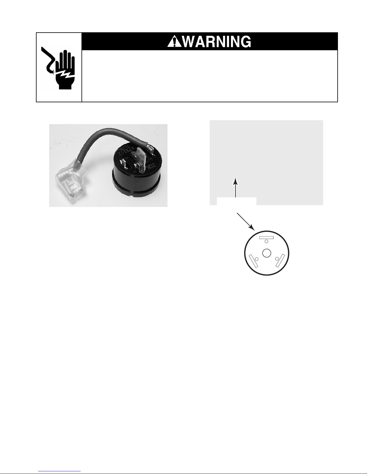
Electrical Shock Hazard
Disconnect power before servicing.
Replace all parts and panels before operating.
Failure to do so can result in death or electrical shock.
OVERLOAD PROTECTOR
Refer to page 4-14 for the procedure for servicing the overload protector.
1. Unplug air conditioner or disconnect power.
2. Disconnect the overload protector wires.
3. Set the ohmmeter to the R x 1 scale.
4. Touch the ohmmeter test leads to the
overload protector terminal and connector.
5. The meter should indicate continuity (0 Ω).
COMPRESSOR
Compressor
Terminals
C
Black
(W)
R
Blue
(U)
Refer to page 4-14 for the procedure for servicing the compressor.
1. Unplug air conditioner or disconnect power.
S
(V)
Red
2. Disconnect the three wires from the compressor terminals.
3. Set the ohmmeter to the R x 1 scale.
4. Clip an ohmmeter test lead to the overload
protector terminal C (W).
5. Touch the free test lead to the following
compressor terminals. The meter should
indicate as shown:
Terminal R (U) = 0.5 Ω
Terminal S (V) = 3.16 Ω
Terminal S (V) to R (U) = 3.65 Ω
5-7
Page 58
Electrical Shock Hazard
Disconnect power before servicing.
Replace all parts and panels before operating.
Failure to do so can result in death or electrical shock.
SOLENOID COIL
Refer to page 4-20 for the procedure for servicing the solenoid coil.
1. Unplug air conditioner or disconnect power.
2. Disconnect one of the wires from the solenoid coil terminals.
3. Set the ohmmeter to the R x 100 scale.
4. Touch the ohmmeter test leads to the
solenoid coil terminals. The meter should
indicate between 1480 and 1520 Ω.
5-8
Page 59

DIAGNOSIS & TROUBLESHOOTING
DIAGNOSING THE SEALED SYSTEM
REFRIGERANT CHARGING
The proper refrigerant charge is essential to
proper sealed system operation. Operating the
unit with an improper refrigerant charge will
result in reduced performance and efficiency.
The use of proper charging methods during
servicing will insure that the unit is functioning
as designed, and that its compressor will not be
damaged.
Too much (overcharged) or too little (undercharged) refrigerant in the system can be the
source of compressor failure if uncorrected for
any period of time.
An overcharged system will sometimes return
liquid refrigerant back to the suction side of the
compressor, and eventually cause a mechanical failure within the compressor. This mechanical failure can manifest itself as valve
failure, bearing failure, or some other mechanical failure. The specific type of failure will be
influenced by the amount of liquid being returned to the suction line, and the length of time
that it continues.
An undercharged system will cause the temperature of the suction gas to increase to the
point where it does not provide sufficient cooling for the compressor motor. When this occurs, the motor winding temperature will increase, causing the motor to overheat, and
open the compressor’s overload protector. Continued overheating of the motor windings and
cycling of the overload, will eventually lead to
compressor motor, or overload failure.
METHOD OF CHARGING
The preferred and most accurate method for
charging the PTAC system is called the
“Weighed in Charge Method,” and is applicable to all units. This method should always
be used whenever a charge is removed from a
unit for a leak repair, compressor replacement,
or when there is no refrigerant charge left in the
unit.
To use this method, perform the following
steps:
1. Install a piercing valve to remove refrigerant from the sealed system. NOTE: The
piercing valve must be removed from the
system before recharging.
2. Recover the refrigerant in accordance with
EPA regulations.
3. Install a process tube to the sealed system.
4. Make the necessary repairs to the system.
5. Evacuate the system to 300 microns or
less.
6. Weigh in the refrigerant with the proper
quantity of R-22 refrigerant.
7. Start the unit, and verify its performance.
8. Crimp the process tube closed, and solder
the end shut.
6-1
Page 60
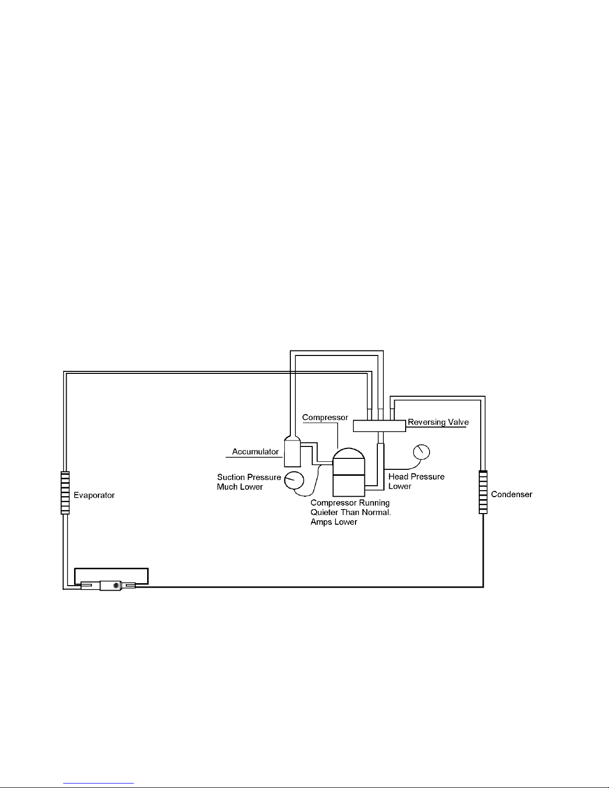
AN UNDERCHARGED SYSTEM
An undercharged system will result in poor
performance (low pressures) in both the heating and cooling cycle.
Whenever you service a unit with an undercharge of refrigerant, you can usually suspect
a leak. The leak must be repaired before charging the unit.
To check for an undercharged system, turn the
unit on, and allow the compressor to run long
enough (15 to 20 minutes) to establish working
pressures in the system.
During the cooling cycle, listen carefully at the
exit of the capillary tube into the evaporator. An
undercharged system will cause an intermittent “hissing” and “gurgling” sound. Intermittent frosting and thawing of the evaporator is
another indication of a low charge. However,
frosting and thawing can also be caused by
insufficient air over the evaporator.
Check for an undercharged system at the
compressor. If the compressor seems quieter
than normal, it is an indication of a low refrigerant charge. A check of the amperage drawn by
the compressor motor should show a lower
reading (check the unit’s specifications).
After the unit has run 10 to 15 minutes, check
the gauge pressures.
Gauges connected to an undercharged system will have low head pressures, and substantially low suction pressures.
Undercharged System
6-2
Page 61
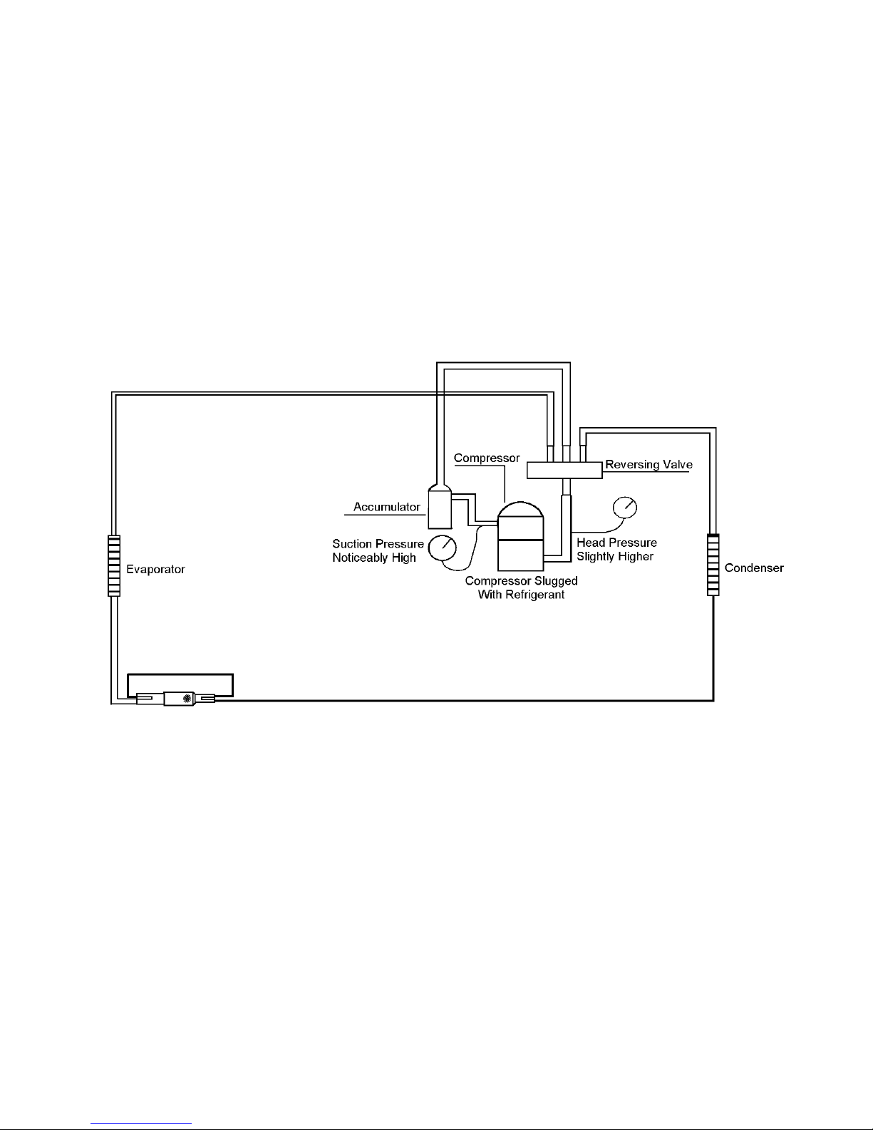
AN OVERCHARGED SYSTEM
To help confirm an overcharged system, remove some of the charge. If conditions improve, the system is most likely overcharged. If
conditions do not improve, non-condensables
(air) are indicated.
Whenever an overcharged system is indicated,
always make sure that there are no airflow
problems. Improper airflow over the evaporator coil may indicate some of the same symptoms as with an overcharged system.
An overcharge can cause the compressor to
fail, since liquid refrigerant is entering the suction line.
The charge for any system is critical. When the
compressor is noisy, and you are sure that
there is sufficient airflow over the evaporator
coils, suspect an overcharge. Icing of the evaporator will not be encountered, because the
refrigerant will boil later, if at all. Gauges connected to the system will usually have a higher
head pressure (depending upon amount of
overcharge). Suction pressure should be slightly
higher.
Overcharged System
6-3
Page 62
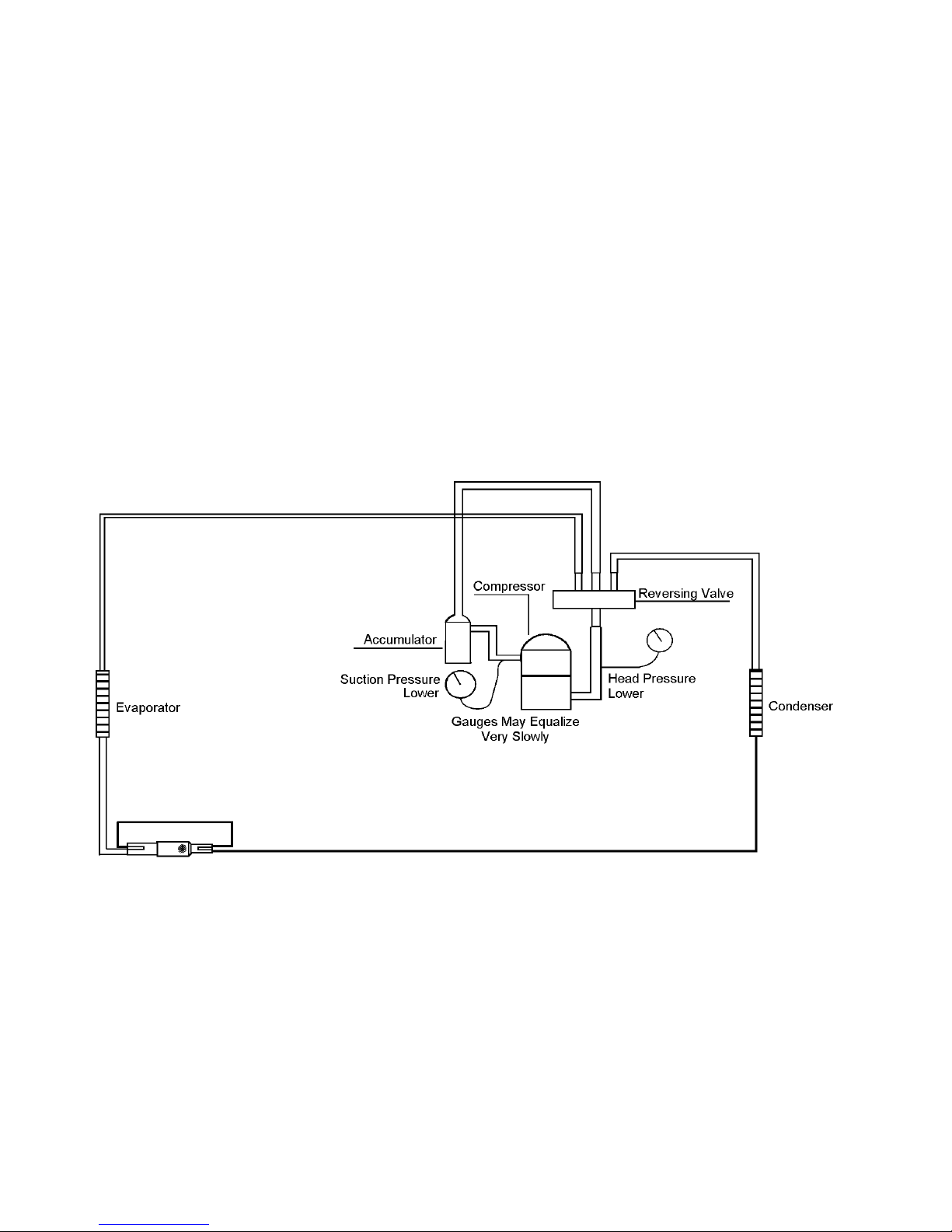
A RESTRICTED SYSTEM
The following procedures are the more common problems and solutions to the problems of
a restricted sealed system. There are two
types of refrigerant restrictions:
• Partial restrictions
• Complete restrictions
With a partial restriction, some of the refrigerant will circulate through the system.
With a complete restriction there is no circulation of refrigerant in the system.
When gauges are connected to a completely
restricted system, the gauges will run in a deep
vacuum. When the unit is turned off, the gauges
will not equalize at all.
A quick check for either condition begins at the
evaporator. With a partial restriction, there may
be a “gurgling” sound at the capillary tube
entrance to the evaporator. The evaporator in
a partial restriction could be partially frosted, or
have an ice ball close to the entrance of the
capillary tube. Frost may continue on the suction line back to the compressor.
Restricted refrigerant systems will display the
same symptoms as a “low-charge condition.”
When the unit is turned off, the gauges may
equalize very slowly.
Often a partial restriction of any type can be
found by feeling for a temperature difference
from one side of the restriction to the other.
Partially Restricted System
6-4
Page 63
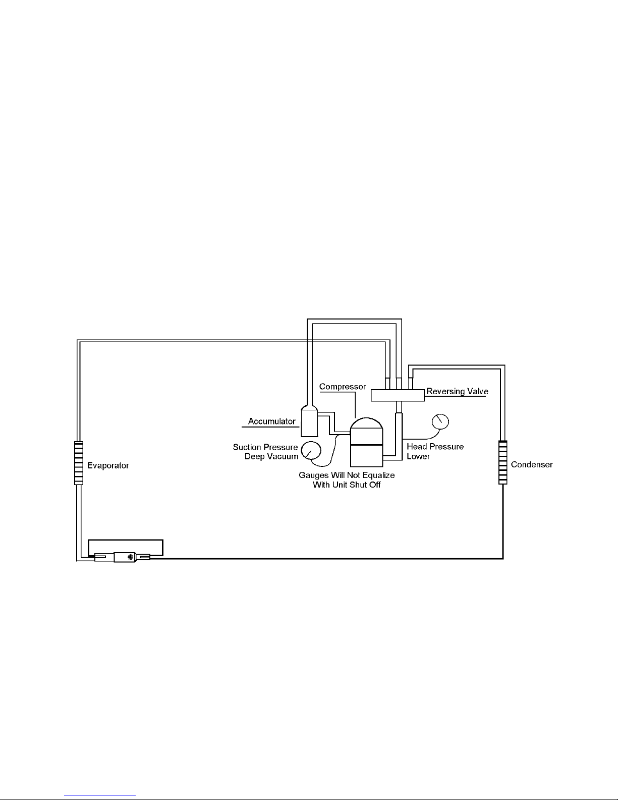
With a complete restriction, there will be no
sound at the capillary tube entrance. An amperage check of the compressor with a partial
restriction may show normal current when compared to the unit specification. The current
drawn may be considerably less than normal,
since the compressor is running in a deep
vacuum (no load). Much of the area of the
condenser will be relatively cool, since most, or
all of the liquid refrigerant will be stored there.
CAPILLARY TUBE RESTRICTIONS
All Whirlpool PTAC units are equipped with
capillary tubes. When checking for a restricted
capillary tube, use the following procedure.
1. Connect pressure gauges to the unit.
2. Start the unit in the “cooling” mode. If the
pressures are normal after a few minutes of
operation, the check valve and cooling capillary are not restricted.
3. Switch the unit to the “heating” mode, and
observe the gauge readings after a few
minutes of running time. If the system pressure is lower than normal, the heating capillary is restricted.
4. If the operating pressures are lower than
normal in both the heating and cooling
modes, the cooling capillary is restricted.
Completely Restricted System
6-5
Page 64
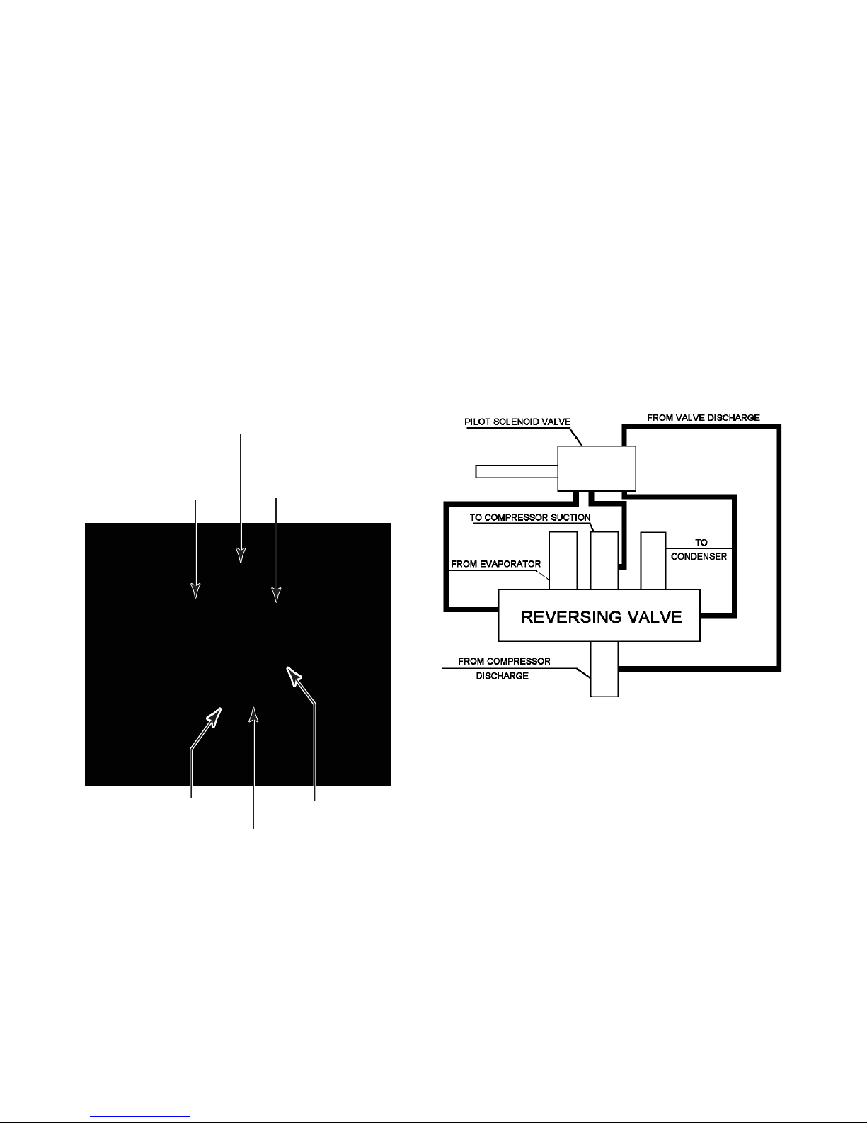
THE REVERSING VALVE
The reversing valve controls the direction of
refrigerant flow to the indoor and outdoor coils.
The valve consists of a pressure-operated
main valve, and a pilot valve that is actuated by
a solenoid plunger. The solenoid is energized
during the “heating” cycle only. The reversing
valve used in the PTAC system is a 2-position,
4-way valve.
The single tube on one side of the main valve
body is the high-pressure inlet to the valve from
the compressor. The center tube on the opposite side is connected to the low pressure
(suction) side of the system. The other two
tubes are connected to the evaporator and
condenser.
Left Tube To Evaporator Line
Center Tube
Low Pressure
Suction Line
Right Tube
To Condenser
Small capillary tubes connect each end of the
main valve cylinder to the “A” and “B” ports of
the pilot valve. A third capillary is a common
return line from these ports to the suction tube
on the main valve body. Four-way reversing
valves also have a capillary tube from the
compressor discharge tube to the pilot valve.
The piston assembly in the main valve can only
be shifted by the pressure differential between
the high and low sides of the system. The pilot
section of the valve opens and closes ports for
the small capillary tubes to the main valve, to
cause it to shift.
NOTE: The sealed system operating pressures must be near normal before the valve
can shift.
Solenoid CoilHigh Pressure Inlet Line
Reversing Valve
6-6
Page 65
TROUBLESHOOTING CHARTS
Refrigerant System—Cooling
Low Suction Pressure High Suction Pressure Low Head Pressure High Head Pressure
Low Load Conditions High Load Conditions Low Load Conditions High Load Conditions
Low Airflow Across
Evaporator
Refrigerant System
Restriction
Moisture In System Defective Compressor Defective Compressor
High Airflow Across
Evaporator
Reversing Valve
Not Fully Seated
Refrigerant System
Restriction
Reversing Valve
Not Fully Seated
Undercharged SystemOvercharged SystemUndercharged System
Low Airflow Across
Condenser
Overcharged System
Non-Condensables
(Air) In System
Refrigerant System—Heating
Low Suction Pressure High Suction Pressure Low Head Pressure High Head Pressure
Low Airflow Across
Condenser
Refrigerant System
Restriction
Moisture In System Defective Compressor Defective Compressor
Temperature Too High
Outdoor Ambient
Reversing Valve
Not Fully Seated
Refrigerant System
Restriction
Reversing Valve
Not Fully Seated
Undercharged SystemOvercharged System Overcharged SystemUndercharged System
6-7
Outdoor Ambient
Temperature Too High
For Operation In Heating
Low Airflow Across
Evaporator
Non-Condensables
(Air) In System
Page 66
Electrical Troubleshooting—Heat Pump
System Cools When
Heating Is Desired
Is Line Voltage Present
At Solenoid Valve?
YES
Is Solenoid Coil Good?
YES
Reversing Valve Stuck
Replace Reversing Valve
NO
NO
Is Selector Switch
Set For Heat?
Replace Solenoid Coil
6-8
Page 67
WIRING DIAGRAMS & STRIP CIRCUITS
Due to the large number of models for the
Packaged Terminal Air Conditioners, the Wiring Diagrams and Strip Circuits will be broken
down as follows:
• The charts on this page show the model
numbers, the associated wiring diagram
numbers, and the pages on which the
diagrams are located (parentheses).
Wiring Diagram Charts
Model #
ATE0743BPP 5 (7-7)
ATE0743CPP 1 (7-5)
ATE0743RPP 5 (7-7)
ATE0743SPP 1 (7-5)
ATE0753BPP 7 (7-8)
ATE0753CPP 3 (7-6)
ATE0753RPP 7 (7-8)
ATE0753SPP 3 (7-6)
ATE0943BPP 5 (7-7)
ATE0943CPP 1 (7-5)
ATE0943RPP 5 (7-7)
ATE0943SPP 1 (7-5)
ATE0953BPP 7 (7-8)
ATE0953CPP 3 (7-6)
ATE0953RPP 7 (7-8)
ATE0953SPP 3 (7-6)
ATE1243BPP 5 (7-7)
ATE1243CPP 1 (7-5)
ATE1243RPP 5 (7-7)
ATE1243SPP 1 (7-5)
ATE1253BPP 7 (7-8)
ATE1253CPP 3 (7-6)
ATE1253RPP 7 (7-8)
ATE1253SPP 3 (7-6)
ATE1545BPP 5 (7-7)
ATE1545CPP 1 (7-5)
ATE1545RPP 5 (7-7)
ATE1545SPP 1 (7-5)
ATE1555BPP 7 (7-8)
ATE1555CPP 3 (7-6)
ATE1555RPP 7 (7-8)
ATE1555SPP 3 (7-6)
Wiring Diagram #
And (Page #)
• Page 7-2 shows the strip circuit chart for
“standard control” models. Page 7-4 shows
the strip circuit chart for “remote thermostat” models.
• Each strip circuit has a reference number
that is listed in the charts. The “condition”
for each strip circuit is shown at the top of
each column, along with the page number
(parentheses) for the strip circuit.
Model #
ATR0743BPP 6 (7-8)
ATR0743CPP 2 (7-6)
ATR0743RPP 6 (7-8)
ATR0743SPP 2 (7-6)
ATR0753BPP 8 (7-9)
ATR0753CPP 4 (7-7)
ATR0753RPP 8 (7-9)
ATR0753SPP 4 (7-7)
ATR0943BPP 6 (7-8)
ATR0943CPP 2 (7-6)
ATR0943RPP 6 (7-8)
ATR0943SPP 2 (7-6)
ATR0953BPP 8 (7-9)
ATR0953CPP 4 (7-7)
ATR0953RPP 8 (7-9)
ATR0953SPP 4 (7-7)
ATR1243BPP 6 (7-8)
ATR1243CPP 2 (7-6)
ATR1243RPP 6 (7-8)
ATR1243SPP 2 (7-6)
ATR1253BPP 8 (7-9)
ATR1253CPP 4 (7-7)
ATR1253RPP 8 (7-9)
ATR1253SPP 4 (7-7)
ATR1545BPP 6 (7-8)
ATR1545CPP 2 (7-6)
ATR1545RPP 6 (7-8)
ATR1545SPP 2 (7-6)
ATR1555BPP 8 (7-9)
ATR1555CPP 4 (7-7)
ATR1555RPP 8 (7-9)
ATR1555SPP 4 (7-7)
Wiring Diagram #
And (Page #)
7-1
Page 68
Strip Circuit Chart For Standard Control Models
Model #
ATE0743CPP#6 - Pg. 7-11 NA
ATE0743SPP#6 - Pg. 7-11 NA
ATE0753CP
ATE0753SP
ATE0943CP
ATE0943SP
ATE0953CP
ATE0953SP
ATE1243CP
ATE1243SP
ATE1253CP
ATE1253SP
ATE1545CP
ATE1545SP
ATE1555CP
ATE1555CP
ATR0743CP
ATR0743SP
ATR0753CP
ATR0753SP
ATR0943CP
ATR0943SP
ATR0953CP
ATR0953SP
ATR1243CP
ATR1243SP
ATR1253CP
ATR1253SPP#6 - Pg. 7-11 #7 - Pg. 7-12
ATR1545CP
ATR1545SP
ATR1555CP
ATR1555SP
Compressor
Cooling
P#6 - Pg. 7-11 NA
P#6 - Pg. 7-11 NA
P#6 - Pg. 7-11 NA
P#6 - Pg. 7-11 NA
P#6 - Pg. 7-11 NA
P#6 - Pg. 7-11 NA
P#6 - Pg. 7-11 NA
P#6 - Pg. 7-11 NA
P#6 - Pg. 7-11 NA
P#6 - Pg. 7-11 NA
P#6 - Pg. 7-11 NA
P#6 - Pg. 7-11 NA
P#6 - Pg. 7-11 NA
P#6 - Pg. 7-11 NA
P#6 - Pg. 7-11 #7 - Pg. 7-12
P#6 - Pg. 7-11 #7 - Pg. 7-12
P#6 - Pg. 7-11 #7 - Pg. 7-12
P#6 - Pg. 7-11 #7 - Pg. 7-12
P#6 - Pg. 7-11 #7 - Pg. 7-12
P#6 - Pg. 7-11 #7 - Pg. 7-12
P#6 - Pg. 7-11 #7 - Pg. 7-12
P#6 - Pg. 7-11 #7 - Pg. 7-12
P#6 - Pg. 7-11 #7 - Pg. 7-12
P#6 - Pg. 7-11 #7 - Pg. 7-12
P#6 - Pg. 7-11 #7 - Pg. 7-12
P#6 - Pg. 7-11 #7 - Pg. 7-12
P#6 - Pg. 7-11 #7 - Pg. 7-12
P#6 - Pg. 7-11 #7 - Pg. 7-12
P#6 - Pg. 7-11 #7 - Pg. 7-12
Compressor
Heating
Electric Heat Reversing Valve
#10 - Pg. 7-13
#10 - Pg. 7-13
#10 - Pg. 7-13
#10 - Pg. 7-13
#10 - Pg. 7-13
#10 - Pg. 7-13
#10 - Pg. 7-13
#10 - Pg. 7-13
#10 - Pg. 7-13
#10 - Pg. 7-13
#10 - Pg. 7-13
#10 - Pg. 7-13
#10 - Pg. 7-13
#10 - Pg. 7-13
#10 - Pg. 7-13
#10 - Pg. 7-13
#8 or #9 - Pg. 7-12
#8 or #9 - Pg. 7-12
#8 or #9 - Pg. 7-12
#8 or #9 - Pg. 7-12
#8 or #9 - Pg. 7-12
#8 or #9 - Pg. 7-12
#8 or #9 - Pg. 7-12
#8 or #9 - Pg. 7-12
#8 or #9 - Pg. 7-12
#8 or #9 - Pg. 7-12
#8 or #9 - Pg. 7-12
#8 or #9 - Pg. 7-12
#8 or #9 - Pg. 7-12
#8 or #9 - Pg. 7-12
#8 or #9 - Pg. 7-12
#8 or #9 - Pg. 7-12
NA
NA
NA
NA
NA
NA
NA
NA
NA
NA
NA
NA
NA
NA
NA
NA
#7, #8, or #9 - Pg. 7-12
#7, #8, or #9 - Pg. 7-12
#7, #8, or #9 - Pg. 7-12
#7, #8, or #9 - Pg. 7-12
#7, #8, or #9 - Pg. 7-12
#7, #8, or #9 - Pg. 7-12
#7, #8, or #9 - Pg. 7-12
#7, #8, or #9 - Pg. 7-12
#7, #8, or #9 - Pg. 7-12
#7, #8, or #9 - Pg. 7-12
#7, #8, or #9 - Pg. 7-12
#7, #8, or #9 - Pg. 7-12
#7, #8, or #9 - Pg. 7-12
#7, #8, or #9 - Pg. 7-12
#7, #8, or #9 - Pg. 7-12
#7, #8, or #9 - Pg. 7-12
7-2
Page 69
Model # Fan Only
Cool/Heat-
Continuous
Run Fan
Cool-
Cycling
Fan
Heat-Cycling
Fan
ATE0743CPP #1 - Pg. 7-10 #2 - Pg. 7-10 #3 - Pg. 7-10 #4 - Pg. 7-11
ATE0743SPP #1 - Pg. 7-10 #2 - Pg. 7-10 #3 - Pg. 7-10 #4 - Pg. 7-11
ATE0753CPP #1 - Pg. 7-10 #2 - Pg. 7-10 #3 - Pg. 7-10 #4 - Pg. 7-11
ATE0753SPP #1 - Pg. 7-10 #2 - Pg. 7-10 #3 - Pg. 7-10 #4 - Pg. 7-11
ATE0943CPP #1 - Pg. 7-10 #2 - Pg. 7-10 #3 - Pg. 7-10 #4 - Pg. 7-11
ATE0943SPP #1 - Pg. 7-10 #2 - Pg. 7-10 #3 - Pg. 7-10 #4 - Pg. 7-11
ATE0953CPP #1 - Pg. 7-10 #2 - Pg. 7-10 #3 - Pg. 7-10 #4 - Pg. 7-11
ATE0953SPP #1 - Pg. 7-10 #2 - Pg. 7-10 #3 - Pg. 7-10 #4 - Pg. 7-11
ATE1243CPP #1 - Pg. 7-10 #2 - Pg. 7-10 #3 - Pg. 7-10 #4 - Pg. 7-11
ATE1243SPP #1 - Pg. 7-10 #2 - Pg. 7-10 #3 - Pg. 7-10 #4 - Pg. 7-11
ATE1253CPP #1 - Pg. 7-10 #2 - Pg. 7-10 #3 - Pg. 7-10 #4 - Pg. 7-11
ATE1253SPP #1 - Pg. 7-10 #2 - Pg. 7-10 #3 - Pg. 7-10 #4 - Pg. 7-11
ATE1545CPP #1 - Pg. 7-10 #2 - Pg. 7-10 #3 - Pg. 7-10 #4 - Pg. 7-11
ATE1545SPP #1 - Pg. 7-10 #2 - Pg. 7-10 #3 - Pg. 7-10 #4 - Pg. 7-11
ATE1555CPP #1 - Pg. 7-10 #2 - Pg. 7-10 #3 - Pg. 7-10 #4 - Pg. 7-11
ATE1555CPP #1 - Pg. 7-10 #2 - Pg. 7-10 #3 - Pg. 7-10 #4 - Pg. 7-11
ATR0743CPP #1 - Pg. 7-10 #2 - Pg. 7-10 #3 - Pg. 7-10 #4 - Pg. 7-11
ATR0743SPP #1 - Pg. 7-10 #2 - Pg. 7-10 #3 - Pg. 7-10 #4 - Pg. 7-11
ATR0753CPP #1 - Pg. 7-10 #2 - Pg. 7-10 #3 - Pg. 7-10 #4 - Pg. 7-11
ATR0753SPP #1 - Pg. 7-10 #2 - Pg. 7-10 #3 - Pg. 7-10 #4 - Pg. 7-11
ATR0943CPP #1 - Pg. 7-10 #2 - Pg. 7-10 #3 - Pg. 7-10 #4 - Pg. 7-11
ATR0943SPP #1 - Pg. 7-10 #2 - Pg. 7-10 #3 - Pg. 7-10 #4 - Pg. 7-11
ATR0953CPP #1 - Pg. 7-10 #2 - Pg. 7-10 #3 - Pg. 7-10 #4 - Pg. 7-11
ATR0953SPP #1 - Pg. 7-10 #2 - Pg. 7-10 #3 - Pg. 7-10 #4 - Pg. 7-11
ATR1243CPP #1 - Pg. 7-10 #2 - Pg. 7-10 #3 - Pg. 7-10 #4 - Pg. 7-11
ATR1243SPP #1 - Pg. 7-10 #2 - Pg. 7-10 #3 - Pg. 7-10 #4 - Pg. 7-11
ATR1253CPP #1 - Pg. 7-10 #2 - Pg. 7-10 #3 - Pg. 7-10 #4 - Pg. 7-11
ATR1253SPP #1 - Pg. 7-10 #2 - Pg. 7-10 #3 - Pg. 7-10 #4 - Pg. 7-11
ATR1545CPP #1 - Pg. 7-10 #2 - Pg. 7-10 #3 - Pg. 7-10 #4 - Pg. 7-11
ATR1545SPP #1 - Pg. 7-10 #2 - Pg. 7-10 #3 - Pg. 7-10 #4 - Pg. 7-11
ATR1555CPP #1 - Pg. 7-10 #2 - Pg. 7-10 #3 - Pg. 7-10 #4 - Pg. 7-11
ATR1555SPP #1 - Pg. 7-10 #2 - Pg. 7-10 #3 - Pg. 7-10 #4 - Pg. 7-11
7-3
Page 70
Strip Circuit Chart For Remote Thermostat Models
Model #
ATE0743BPP #12 - Pg. 7-14 NA #17 - Pg. 7-17 NA #11 - Pg. 7-14
ATE0743RPP #12 - Pg. 7-14 NA #17 - Pg. 7-17 NA #11 - Pg. 7-14
ATE0753BPP #12 - Pg. 7-14 NA #17 - Pg. 7-17 NA #11 - Pg. 7-14
ATE0753RPP #12 - Pg. 7-14 NA #17 - Pg. 7-17 NA #11 - Pg. 7-14
ATE0943BPP #12 - Pg. 7-14 NA #17 - Pg. 7-17 NA #11 - Pg. 7-14
ATE0943RPP #12 - Pg. 7-14 NA #17 - Pg. 7-17 NA #11 - Pg. 7-14
ATE0953BPP #12 - Pg. 7-14 NA #17 - Pg. 7-17 NA #11 - Pg. 7-14
ATE0953RPP #12 - Pg. 7-14 NA #17 - Pg. 7-17 NA #11 - Pg. 7-14
ATE1243BPP #12 - Pg. 7-14 NA #17 - Pg. 7-17 NA #11 - Pg. 7-14
ATE1243RPP #12 - Pg. 7-14 NA #17 - Pg. 7-17 NA #11 - Pg. 7-14
ATE1253BPP #12 - Pg. 7-14 NA #17 - Pg. 7-17 NA #11 - Pg. 7-14
ATE1253RPP #12 - Pg. 7-14 NA #17 - Pg. 7-17 NA #11 - Pg. 7-14
ATE1545BPP #12 - Pg. 7-14 NA #17 - Pg. 7-17 NA #11 - Pg. 7-14
ATE1545RPP #12 - Pg. 7-14 NA #17 - Pg. 7-17 NA #11 - Pg. 7-14
ATE1555BPP #12 - Pg. 7-14 NA #17 - Pg. 7-17 NA #11 - Pg. 7-14
ATE1555RPP #12 - Pg. 7-14 NA #17 - Pg. 7-17 NA #11 - Pg. 7-14
ATR0743BPP #12 - Pg. 7-14 #13 - Pg. 7-15 #15 or #16 - Pg. 7-16 #14 - Pg. 7-15 #11 - Pg. 7-14
ATR0743RPP #12 - Pg. 7-14 #13 - Pg. 7-15 #15 or #16 - Pg. 7-16 #14 - Pg. 7-15 #11 - Pg. 7-14
ATR0753BPP #12 - Pg. 7-14 #13 - Pg. 7-15 #15 or #16 - Pg. 7-16 #14 - Pg. 7-15 #11 - Pg. 7-14
ATR0753RPP #12 - Pg. 7-14 #13 - Pg. 7-15 #15 or #16 - Pg. 7-16 #14 - Pg. 7-15 #11 - Pg. 7-14
ATR0943BPP #12 - Pg. 7-14 #13 - Pg. 7-15 #15 or #16 - Pg. 7-16 #14 - Pg. 7-15 #11 - Pg. 7-14
ATR0943RPP #12 - Pg. 7-14 #13 - Pg. 7-15 #15 or #16 - Pg. 7-16 #14 - Pg. 7-15 #11 - Pg. 7-14
ATR0953BPP #12 - Pg. 7-14 #13 - Pg. 7-15 #15 or #16 - Pg. 7-16 #14 - Pg. 7-15 #11 - Pg. 7-14
ATR0953RPP #12 - Pg. 7-14 #13 - Pg. 7-15 #15 or #16 - Pg. 7-16 #14 - Pg. 7-15 #11 - Pg. 7-14
ATR1243BPP #12 - Pg. 7-14 #13 - Pg. 7-15 #15 or #16 - Pg. 7-16 #14 - Pg. 7-15 #11 - Pg. 7-14
ATR1243RPP #12 - Pg. 7-14 #13 - Pg. 7-15 #15 or #16 - Pg. 7-16 #14 - Pg. 7-15 #11 - Pg. 7-14
ATR1253BPP #12 - Pg. 7-14 #13 - Pg. 7-15 #15 or #16 - Pg. 7-16 #14 - Pg. 7-15 #11 - Pg. 7-14
ATR1253RPP #12 - Pg. 7-14 #13 - Pg. 7-15 #15 or #16 - Pg. 7-16 #14 - Pg. 7-15 #11 - Pg. 7-14
ATR1545BPP #12 - Pg. 7-14 #13 - Pg. 7-15 #15 or #16 - Pg. 7-16 #14 - Pg. 7-15 #11 - Pg. 7-14
ATR1545RPP #12 - Pg. 7-14 #13 - Pg. 7-15 #15 or #16 - Pg. 7-16 #14 - Pg. 7-15 #11 - Pg. 7-14
ATR1555BPP #12 - Pg. 7-14 #13 - Pg. 7-15 #15 or #16 - Pg. 7-16 #14 - Pg. 7-15 #11 - Pg. 7-14
ATR1555RPP #12 - Pg. 7-14 #13 - Pg. 7-15 #15 or #16 - Pg. 7-16 #14 - Pg. 7-15 #11 - Pg. 7-14
Compressor
Cooling
Compressor
Heating
Electric Heat
Reversing
Valve
Fan Motor
7-4
Page 71
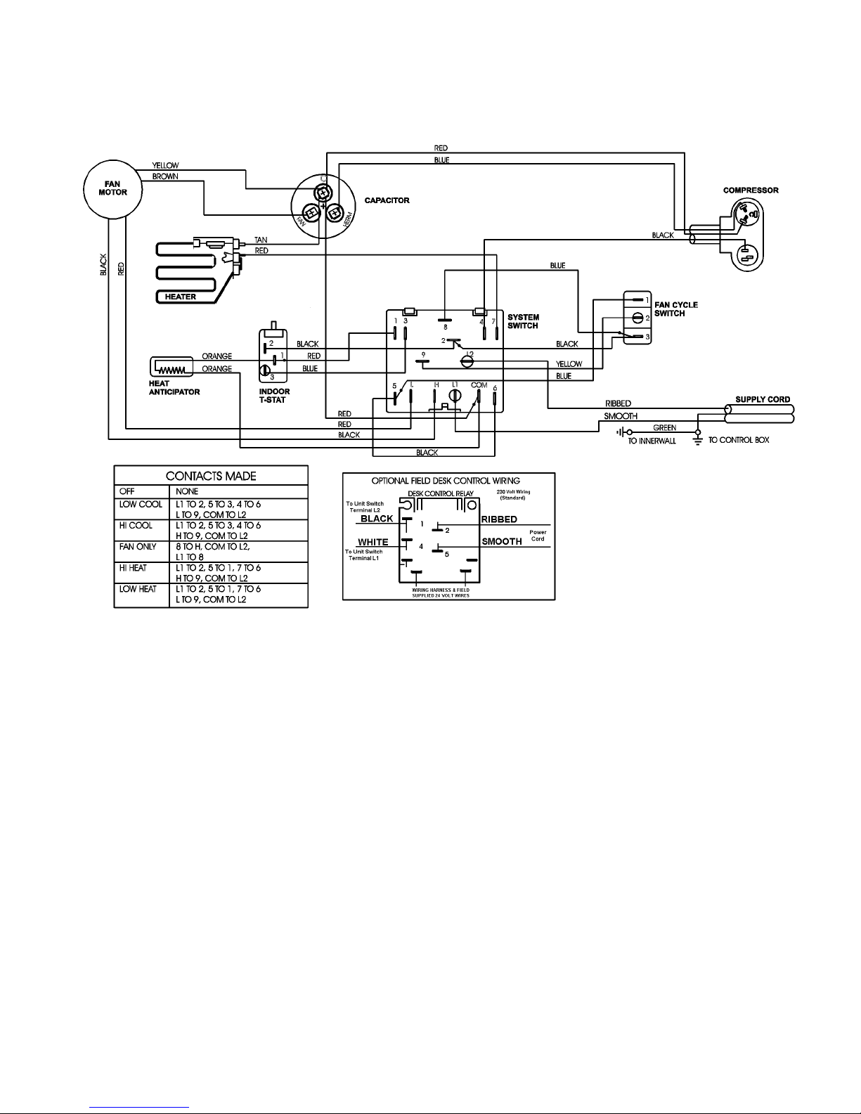
DIAGRAM #1
WIRING DIAGRAMS
7-5
Page 72
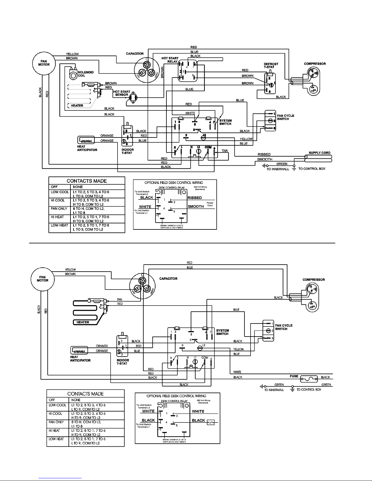
DIAGRAM #2
DIAGRAM #3
7-6
Page 73
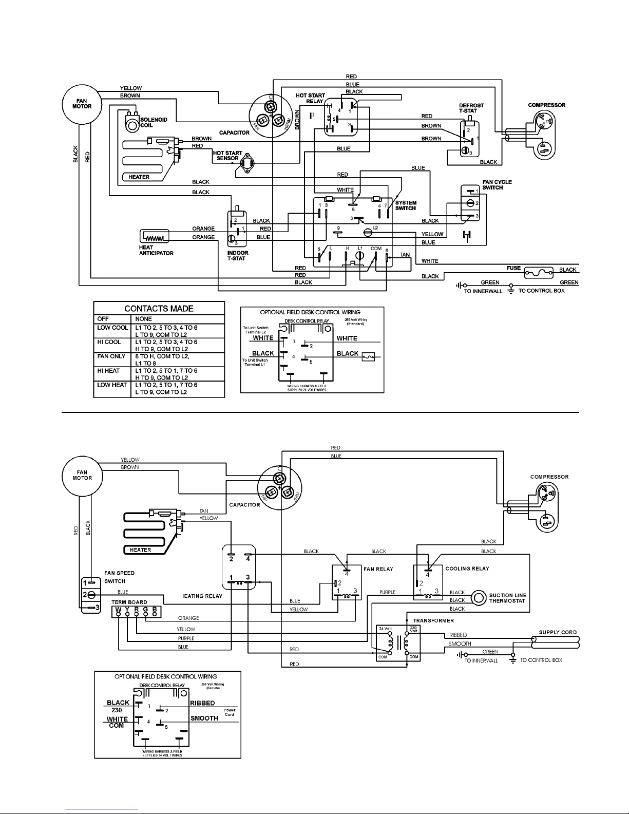
DIAGRAM #4
DIAGRAM #5
7-7
Page 74
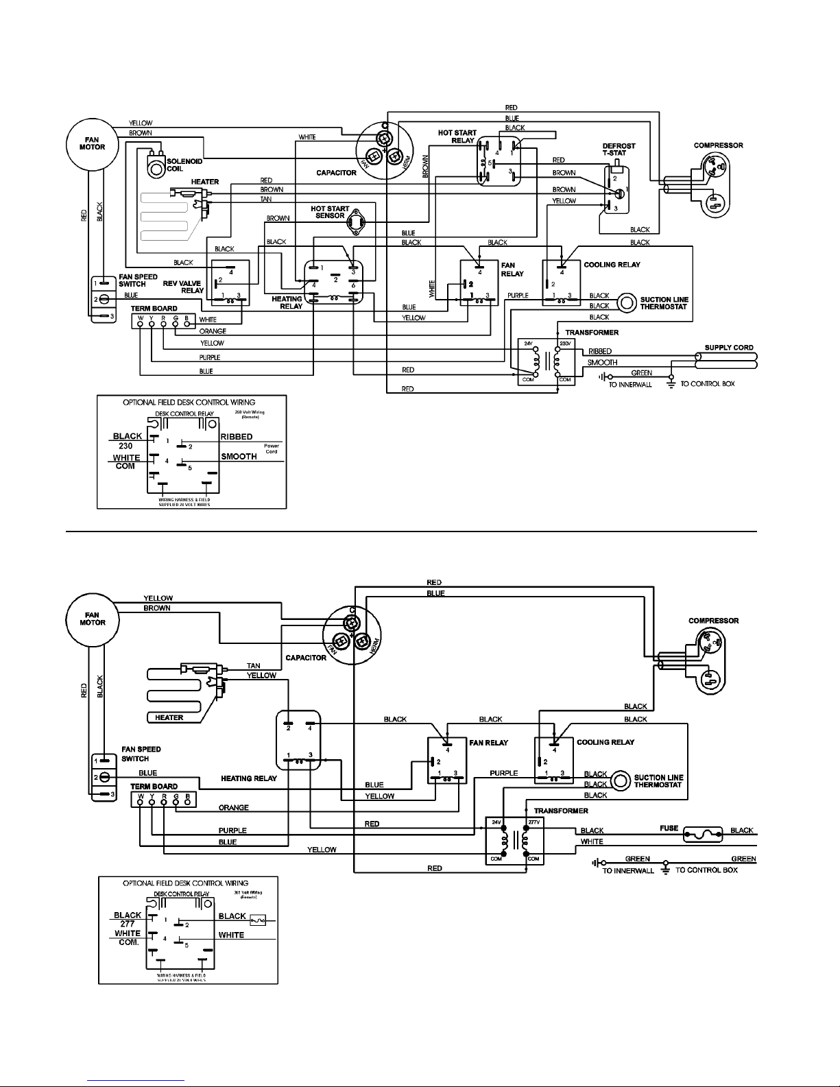
DIAGRAM #6
DIAGRAM #7
7-8
Page 75
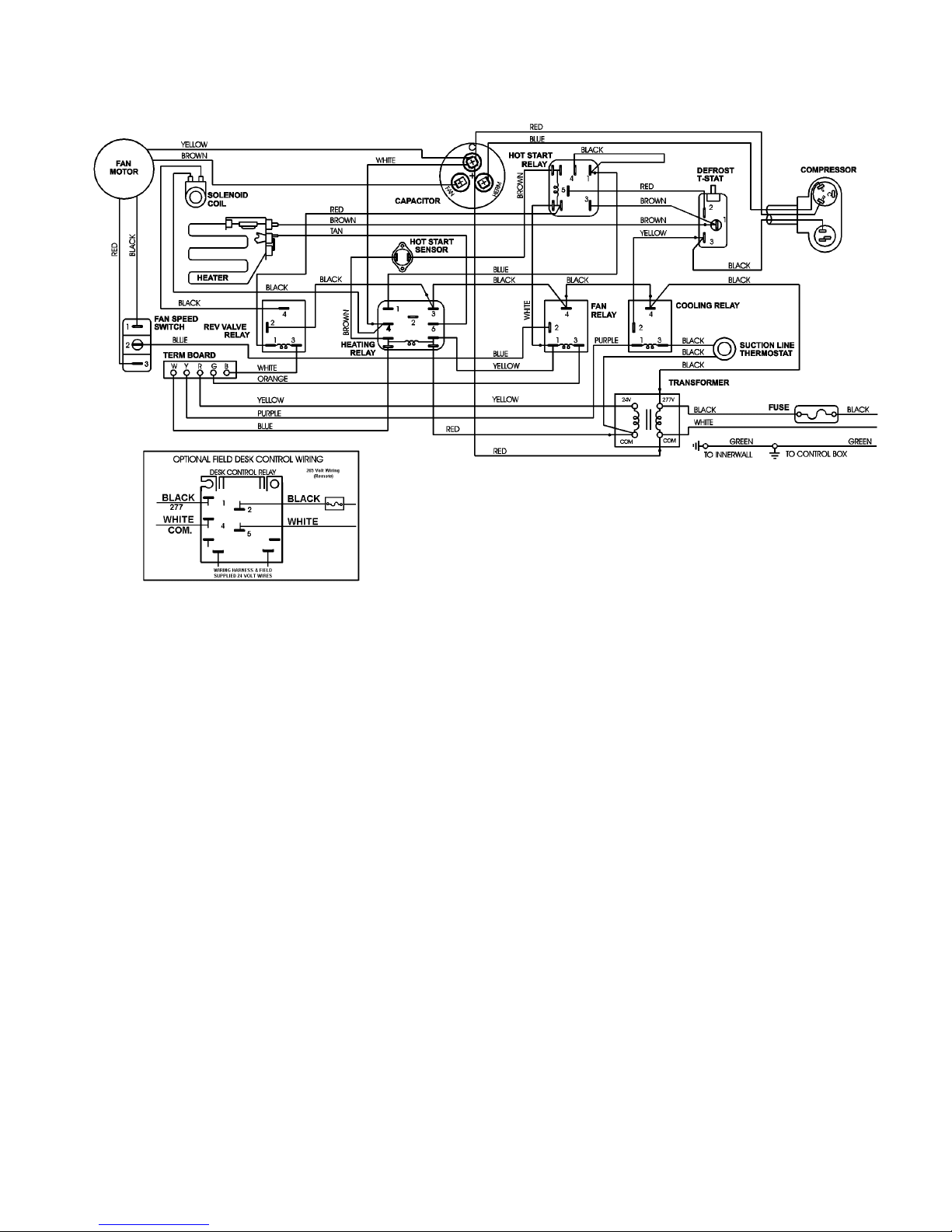
DIAGRAM #8
7-9
Page 76
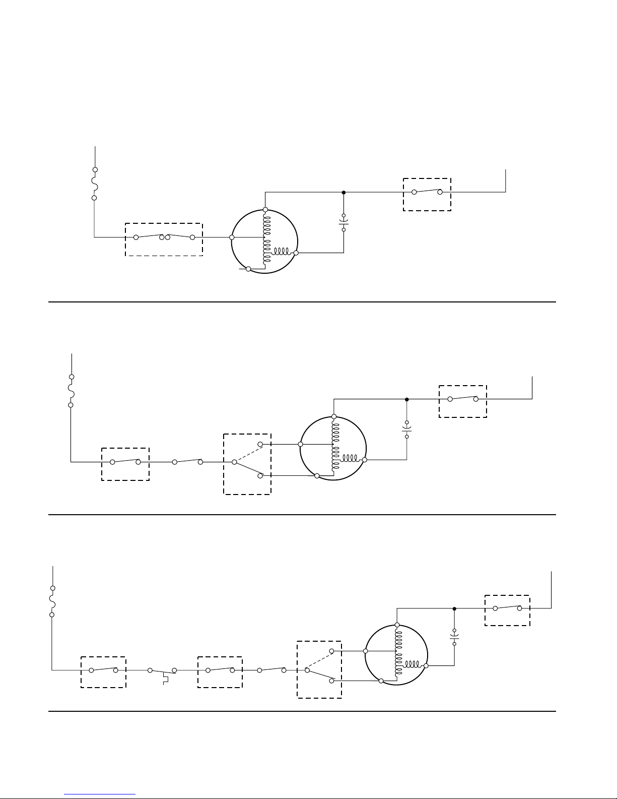
(#1) FAN ONLY
L1
STRIP CIRCUITS
Standard Control Models
FUSE
(265V
MODELS
ONLY)
SYSTEM SWITCH
L1 H
8
BK
FAN MOTOR
YR
C
BR
F
SYSTEM SWITCH
(#2) COOL OR HEAT—FAN MOTOR CONTINUOUS RUN
L1
FUSE
(265V
MODELS
ONLY)
SYSTEM
SWITCH
L1 3 22
SYSTEM
SWITCH
FAN CYCLE
SWITCH
9
(9 - H = HIGH)
(9 - L = LOW)
H
L
(HIGH)
BK
(LOW)
R
YR
BR
FAN MOTOR
COM
L2
SYSTEM SWITCH
C
F
COM
L2
L2
L2
(#3) COOL—FAN MOTOR CYCLING
L1
FUSE
(265V
MODELS
ONLY)
SYSTEM
SWITCH
L1 2 32
MAIN
THERMOSTAT
BK BU BU
SYSTEM
SWITCH
35
FAN CYCLE
SWITCH
12
7-10
(9 - H = HIGH)
(9 - L = LOW)
SYSTEM
SWITCH
H
9
L
(HIGH)
BK
(LOW)
R
FAN MOTOR
L2
SYSTEM SWITCH
Y
BR
R
L2
C
F
COM
Page 77
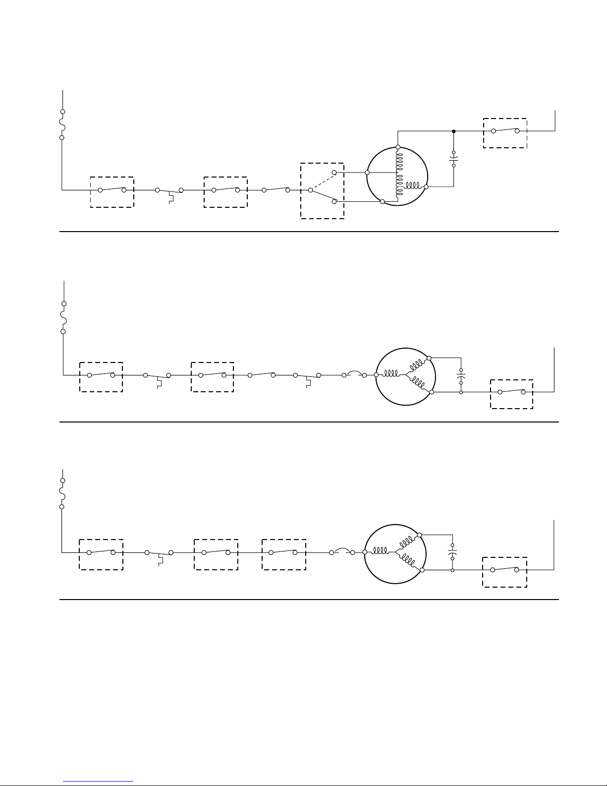
(#4) HEAT—FAN MOTOR CYCLING
L1
FUSE
(265V
MODELS
(9 - H = HIGH)
(9 - L = LOW)
ONLY)
SYSTEM
SYSTEM
SWITCH
L1 2 12
MAIN
THERMOSTAT
BK R BU
SYSTEM
SWITCH
15
FAN CYCLE
SWITCH
12
SWITCH
Y
9
(HIGH)
BK
H
(LOW)
R
L
FAN MOTOR
(#5) COMPRESSOR COOLING (HEAT PUMP MODELS)
L1
FUSE
(265V
MODELS
ONLY)
SYSTEM
SWITCH
L1 2 3
THERMOSTAT
BK BU BU
2
MAIN
SYSTEM
SWITCH
35
HOT START
RELAY
45
DEFROST
THERM.
R
23
OVERLOAD
BK
COMPRESSOR
C
SYSTEM SWITCH
Y
BR
S
R
BU
R
L2
COM
C
F
H
SYSTEM SWITCH
C
R
R
L2
COM
L2
L2
(#6) COMPRESSOR COOLING (NON-HEAT PUMP MODELS)
L1
FUSE
(265V
MODELS
ONLY)
SYSTEM
SWITCH
L1 2 3
2
MAIN
THERMOSTAT
BK BKBU
SYSTEM
SWITCH
35
SYSTEM
SWITCH
64
OVERLOAD
BK
COMPRESSOR
C
BU
S
R
R
H
SYSTEM SWITCH
C
R
COM
L2
L2
7-11
Page 78
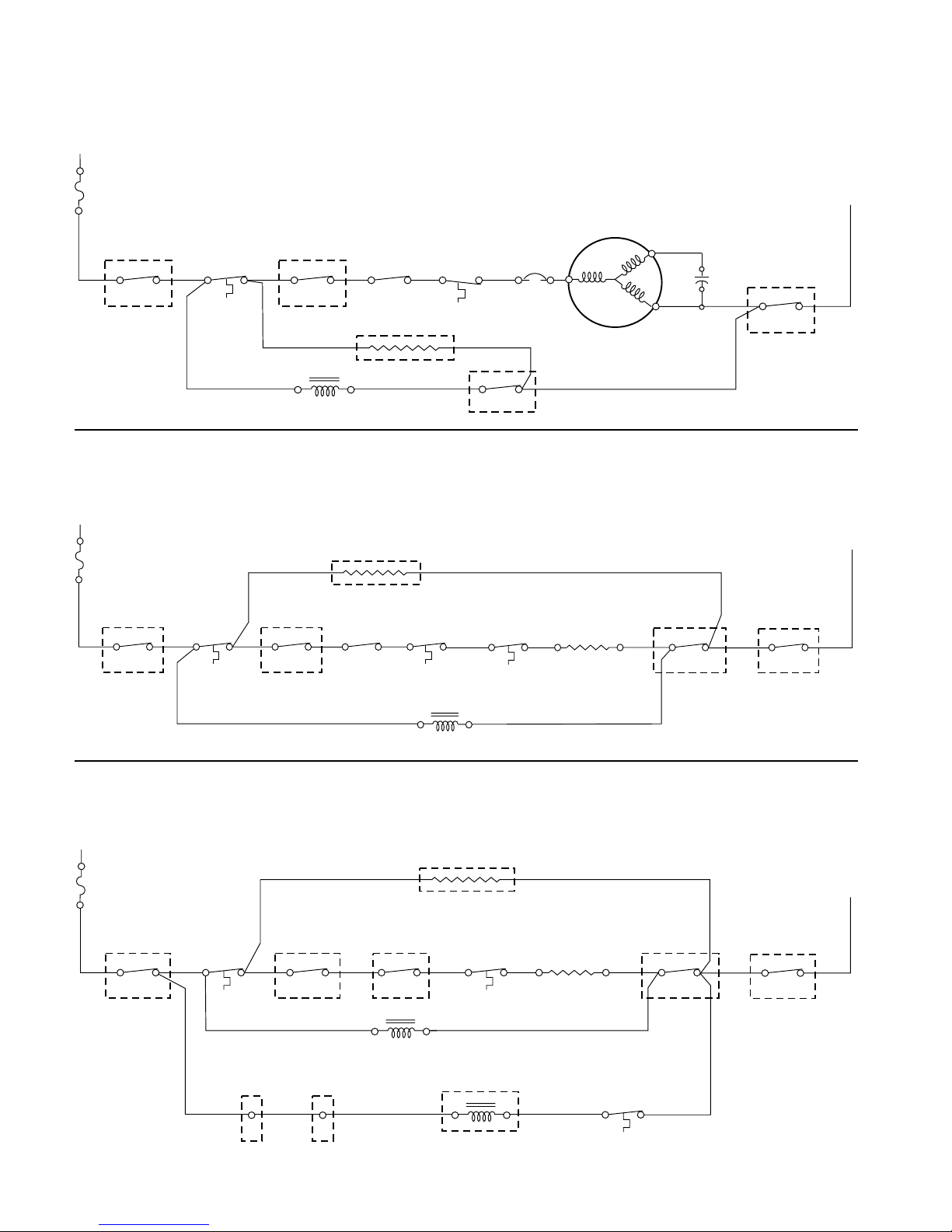
(#7) COMPRESSOR HEATING—HOT START SENSOR OPEN—
ROOM ABOVE 65°F (HEAT PUMP MODELS)
L1
FUSE
(265V
MODELS
ONLY)
SYSTEM
SWITCH
L1 2
THERMOSTAT
BK
2
BK
MAIN
1
SYSTEM
SWITCH
RBU
15
HOT START
RELAY
45
ANTICIPATOR
DEFROST
THERM.
R
23
OVERLOAD
BK
OROR
COMPRESSOR
C
BU
S
R
R
H
SYSTEM SWITCH
C
R
COM
L2
L2
REV. VALVE SOLENOID
76
(#8) ELECTRIC HEAT—HOT START SENSOR OPEN—ROOM ABOVE 65°F
AND OUTDOOR AMBIENT BELOW 47°F (HEAT PUMP MODELS)
L1
FUSE
(265V
MODELS
ANTICIPATOR
OROR
ONLY)
SYSTEM
SWITCH
L1 2
THERMOSTAT
BK
2
MAIN
BK
1
SYSTEM
SWITCH
R
15
HOT START
RELAY
BU
45
DEFROST
THERM.
R
21
REV. VALVE SOLENOID
BR
LIMIT SW
HEAT
HEATING
ELEMENT
SYSTEM
SWITCH
R
7
SYSTEM SWITCH
TN
6
COM
L2
(#9) ELECTRIC HEAT—HOT START SENSOR CLOSED—ROOM BELOW 50°F
(HEAT PUMP MODELS)
L1
FUSE
(265V
MODELS
ONLY)
SYSTEM
SWITCH
L1 2 1
2
MAIN
THERMOSTAT
BK
SYSTEM
SWITCH
R
15
OR OR
HOT START
RELAY
BU
13
ANTICIPATOR
HEAT
LIMIT SW
BR
HEATING
ELEMENT
SYSTEM
SWITCH
R
7
TN
6
SYSTEM SWITCH
L2
COM
L2
L2
BK
SYSTEM SWITCH
BU WH
3
8
REV. VALVE SOLENOID
RELAY COIL
7-12
BKBK
HOT START
HOT START
SENSOR
BR R
Page 79
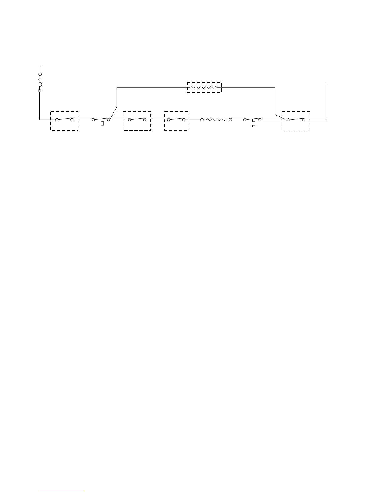
(#10) ELECTRIC HEAT
(NON-HEAT PUMP MODELS)
L1
FUSE
(265V
MODELS
ONLY)
ANTICIPATOR
OR OR
L2
SYSTEM
SWITCH
L1 2 12
MAIN
THERMOSTAT
BK R
SYSTEM
SWITCH
15
SYSTEM
SWITCH
BU
67
R
HEATING
ELEMENT
HEAT
LIMIT SW
SYSTEM SWITCH
L2
COM
7-13
Page 80
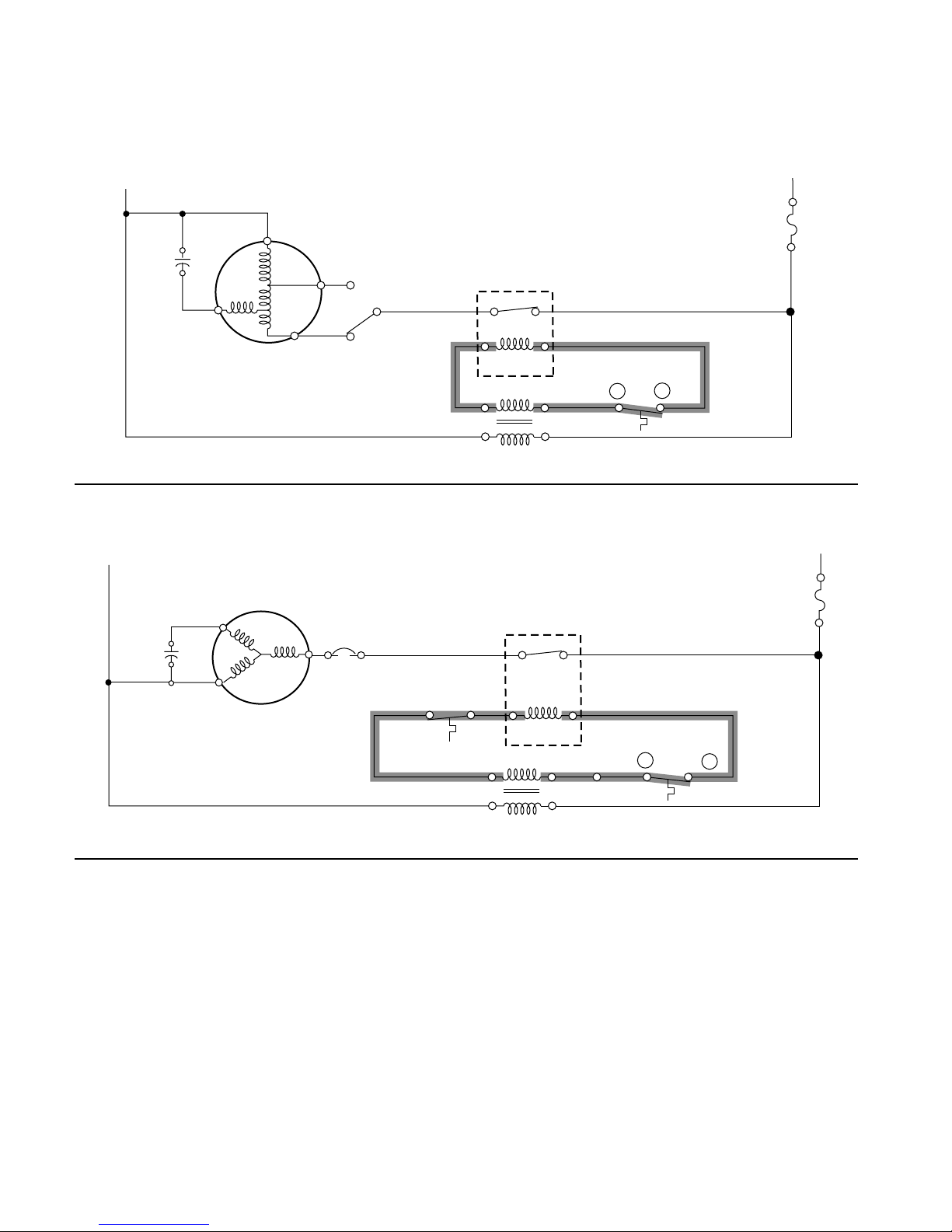
Remote Thermostat Models
(#11) FAN MOTOR OPERATION
L1
Y
C
FAN SPEED
1
BK
F
BR
FAN MOTOR
SWITCH
R
3
(#12) COMPRESSOR COOLING
L1
COMPRESSOR
BU
H
C
S
C
R
OVERLOAD
R
BU
2
BK
SUCTION LINE
THERMO
FAN RELAY
24
COM 24V
TRANSFORMER
COOLING RELAY
24
WALL THERMO.
G
R
PU
L2
FUSE (265V
MODELS ONLY)
L2
FUSE (265V
MODELS ONLY)
BK
COM 24V
TRANSFORMER
7-14
31
WALL THERMO.
R
Y
Y
Page 81
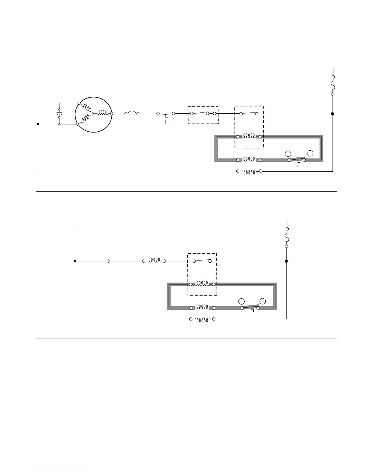
(#13) COMPRESSOR HEATING—HOT START SENSOR OPEN—
ROOM ABOVE 65°F, REVERSING VALVE ENERGIZED (SEE #14)
(HEAT PUMP MODELS)
L2
L1
COMPRESSOR
BU
H
C
S
C
R
OVERLOAD
R
R
DEFROST
BK
THERM.
RD
HOT START
RELAY
BU
RD
(#14) REVERSING VALVE (HEAT PUMP MODELS)
L1
HEATING
BK BK BK
RELAY
REV. VALVE
SOLENOID COIL
REV. VALVE
RELAY
442
HEATING
RELAY
154132 3
COM 24V
TRANSFORMER
FUSE (265V
MODELS ONLY)
FUSE (265V
MODELS ONLY)
BU
WALL THERMO.
R
L2
W
RD
COM 24V
TRANSFORMER
WH
WALL THERMO.
R
B
7-15
Page 82
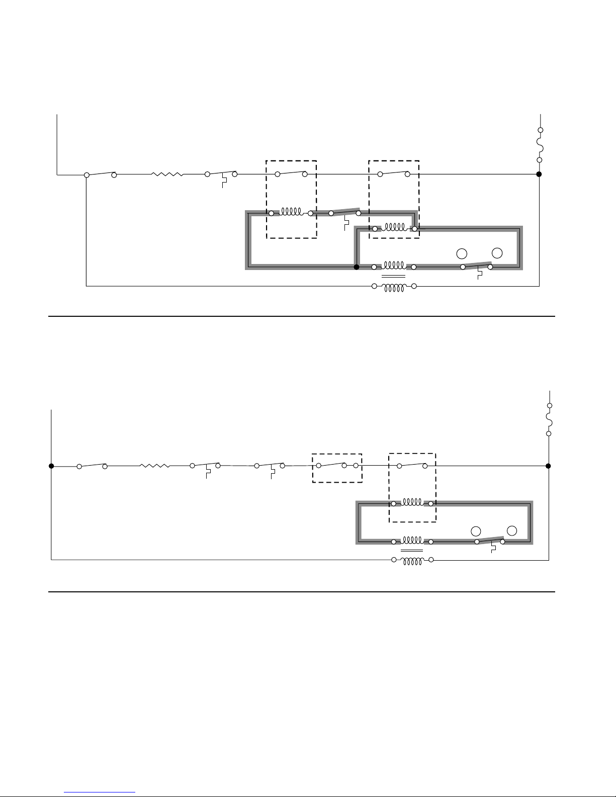
(#15) ELECTRIC HEAT—HOT START SENSOR CLOSED—
ROOM BELOW 50°F, REVERSING VALVE ENERGIZED (SEE #14)
(HEAT PUMP MODELS)
L1
L2
HOT START
ELECTRIC
BK TN BK
4
6
HEATER
HEATER
LIMIT SW
RELAY
BUBR
31
HOT START
SENSOR
RD
HEATING
RELAY
1
3
COM 24V
TRANSFORMER
BU
WALL THERMO.
FUSE (265V
MODELS ONLY)
R
W
(#16) ELECTRIC HEAT—HOT START SENSOR OPEN—ROOM ABOVE 65°F,
AND OUTDOOR AMBIENT BELOW 47°F, REVERSING VALVE ENERGIZED
(SEE #14) (HEAT PUMP MODELS)
L1
HEATING
RELAY
BK TN
4
ELECTRIC
HEATER
6
HEATER
LIMIT SW
DEFROST
THERM.
BR BU
HOT START
RELAY
RD
HEATING
RELAY
1541 312
FUSE (265V
MODELS ONLY)
L2
7-16
RD
COM 24V
TRANSFORMER
BU
WALL THERMO.
R
W
Page 83
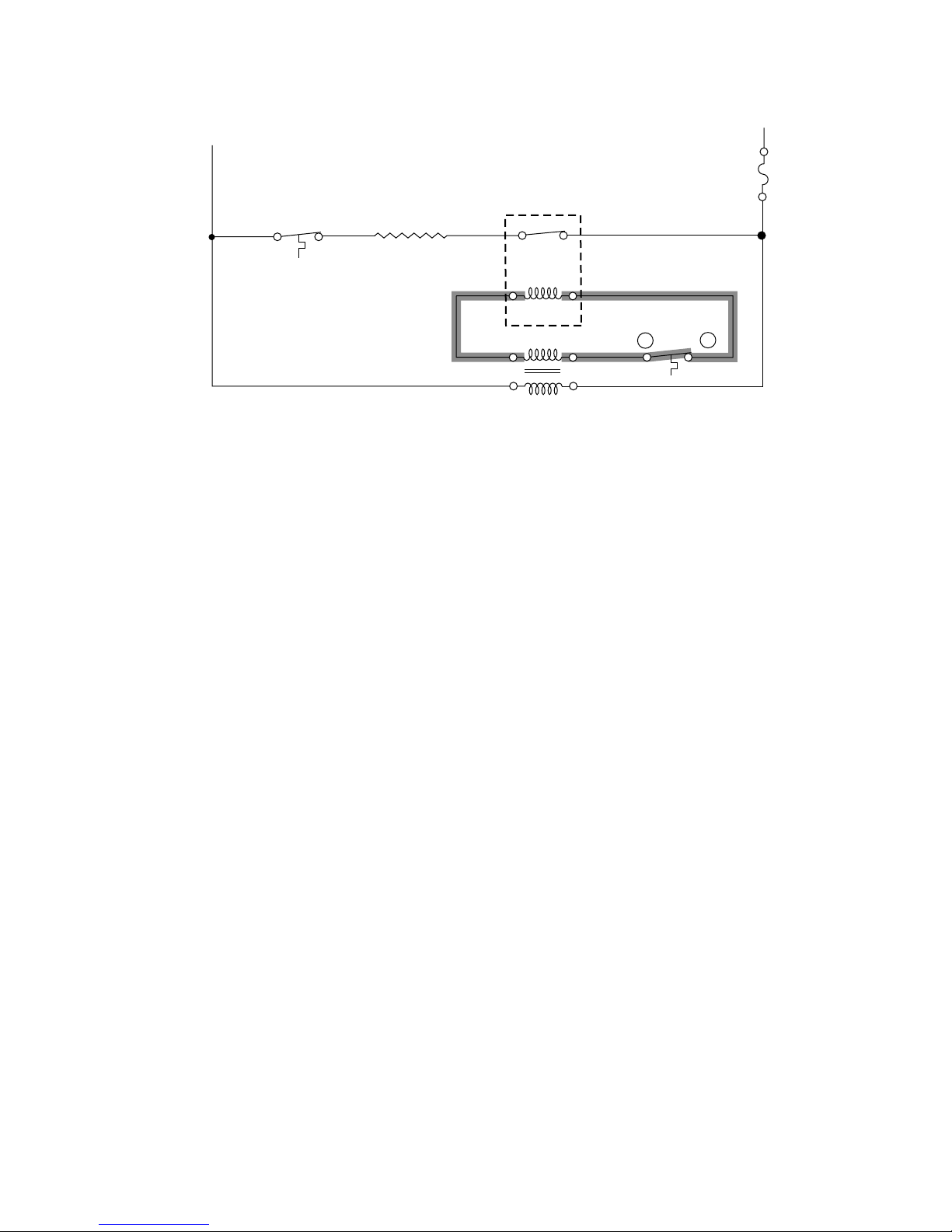
(#17) ELECTRIC HEAT (NON-HEAT PUMP MODELS)
L1
HEATER
LIMIT SWITCH
BK BKY
HEATING ELEMENT
HEATING
RELAY
24
L2
FUSE (265V
MODELS ONLY)
BU
RD
COM 24V
TRANSFORMER
WALL THERMO.
R
W
7-17
Page 84

— NOTES —
7-18
Page 85
TECH TIPS
ROUTINE MAINTENANCE
WARNING
Electrical Shock Hazard
Disconnect power before servicing.
Replace all parts and panels before
operating.
Failure to do so can result in death or
electrical shock.
4. Before reinstalling the chassis in the sleeve,
inspect the indoor blower housing, the
blower wheel, condenser fan blade, and
condenser shroud periodically (every 6 to
12 months). Remove all debris (lint, dirt,
mold, fungus, etc.)
5. Clean the blower housing area and blower
wheel with an antibacterial / antifungal
cleaner.
6. Use a biodegradable cleaning agent and
degreaser on the condenser fan and condenser shroud. Use warm or cold water
when rinsing these items, and allow them
to dry thoroughly before reinstalling them.
NOTE: Units are to be inspected and serviced
by qualified Whirlpool service personnel only.
1. Clean the unit air intake filter after 300 to
350 hours of operation with a mild detergent in warm water. Allow the filter to dry
thoroughly before reinstalling it.
2. The indoor (evaporator) coil, the outdoor
(condenser) coil, and base pan should be
inspected periodically (every 6 to 12
months), and cleaned of all debris (lint,
dirt, leaves, paper, etc.). Clean the coils
and base pan with a soft brush and compressed air, or vacuum.
If you use a pressure washer, be careful
not to bend the aluminum fin pack. Use an
up and down sweeping motion in the direction of the vertical aluminum fin pack.
Cover all electrical components to protect
them from water. Allow the unit to dry
thoroughly,
3. Inspect all gasket material for deterioration.
IMPORTANT: Do not use a caustic coil cleaning agent on the coils or base pan. Use only
a biodegradable cleaning agent.
7. Periodically (every 6 to 12 months) inspect all control components, both electrical and mechanical, as well as the power
supply. Use the proper testing instruments
(voltmeter, ohmmeter, ammeter, wattmeter, etc.) to perform any electrical tests.
8. Use an air conditioning or refrigeration
thermometer to check room, outdoor, and
coil operating temperatures. Use a sling
psychrometer to measure wet bulb temperatures indoors and outdoors.
9. Inspect the inside and outside surrounding areas to ensure that the unit clearances have not been compromised or
altered.
10. Inspect the wall sleeve and drain system
periodically (every 6 to 12 months) and
clean them of all obstructions and debris.
Clean both areas with an antibacterial and
antifungal cleaner, and rinse both items
thoroughly with water. Make sure that the
drain outlets are operating correctly. Check
the sealant around the sleeve and reseal
any areas, as needed.
11. Clean the front cover with a mild detergent
and warm water, and allow it to dry thoroughly before installing it in the chassis.
8-1
Page 86
ACCESSORIES
PART NUMBER DESCRIPTION PHOTO
WALL SLEEVE:
• G-90 zinc coated steel is prepared in an
eleven-step process, then electrostatically
4396585
4396586
4396591
4396595
4396587
coated with a polyester finish, and cured
in an oven for exceptional durability.
• The wall sleeve is insulated for thermal
efficiency. 16″ H x 42″ W x 13-3/4″ D.
STANDARD GRILLE:
• Stamped aluminum.
• Anodized to resist chalking and oxidation.
ARCHITECTURAL LOUVERS:
• Heavy-gauge 6063-T5 aluminum alloy.
• Clear, extruded aluminum.
• Dark bronze acrylic enamel.
• Also available in custom colors.
CONDENSATE DRAIN KIT:
• Attaches to the bottom of the wall sleeve
for internal draining of condensate or to
the rear wall sleeve flange for external
draining.
• Recommended on all units to remove
excess condensate.
• Packaged in quantities of ten.
4396594
4396592
4396590
DEEP WALL SLEEVE EXTENSION:
•4″ deep anodized aluminum extension
that attaches to the outside of the wall
sleeve when the wall is thicker than 13″
thick (11-3/4″ when a subbase is used,
12-3/4″ when a lateral duct is used).
DECORATIVE SUBBASE:
• Provides unit support for walls less than
6″ thick.
• Includes leveling legs, side filler panels
and mounting brackets for electrical
accessories.
• Accepts a circuit breaker, power disconnect switch, or conduit kit.
DESK CONTROL KIT:
• A field installed kit which allows the unit to
be turned On or Off from a remote location.
8-2
Page 87
PART NUMBER DESCRIPTION PHOTO
CONDUIT KIT WITH JUNCTION BOX:
• Makes field wiring connections for direct
4396597
4396593
4396583
wired 265V PTAC/PTHPs.
• Kit includes a means of quick-disconnect
for easy removal of the chassis.
• It can be used with or without a subbase.
DIGITAL REMOTE THERMOSTAT:
• A Honeywell wall-mounted remote thermostat. Requires a single stage cooling
and heating thermostat.
SLEEVE EXTENSION RETROFIT KIT:
• G-90 zinc coated steel, 2.4″ sleeve
extension attached to the room-side of the
sleeve to allow for the installation of a
P-Series unit.
LATERAL DUCT ADAPTER:
4396600
LATERAL DUCT EXTENSION:
4396601
REPLACEMENT FILTER PACK:
ATXFT0
Additional Components:
• Attaches to the PTAC/PTHP unit and
provides a transition to direct up to 35% of
the total CFM to a secondary room, either
left or right of the unit.
• Kit includes duct plenum with a discharge
grille.
• A three foot insulated plenum that attaches to the left or right side of the duct
adapter.
• The extension can be cut to length by the
installer.
• Original equipment return air filters.
• Reusable and can be cleaned by vacuuming or washing.
4396598 Disconnect Switch: Installed in the subbase and provides a means for disconnect-
4396602 Front Cover Side Modifies the method of attaching the front cover when the
Mount Kit: PTAC/PTHP is mounted close to or against the floor.
ing power to the PTAC/PTHP.
8-3
Page 88
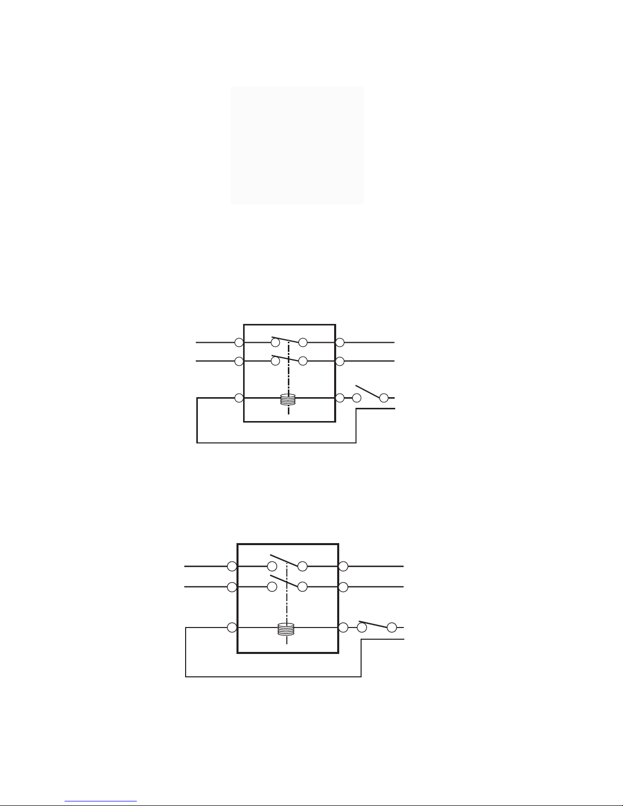
OPTIONAL DESK CONTROL UNIT
The desk control unit allows the air conditioner
to be turned off and on from a remote location.
The unit consists of a pair of switches that are
controlled by a 24-volt relay.
DESK CONTROL RELAY (N.C.)
TO PTAC
SELECTOR
SWITCH
When the desk control switch is closed, the 24volt supply is applied to the relay coil,the contacts open, and the air conditioner will not
The main power supply is wired in series through
the relay contacts. When the desk control
switch is open, the 24-volt supply is removed
from the relay coil, the contacts are closed, and
the air conditioner will operate.
L1 POWER SUPPLY
L2 POWER SUPPLY
24 VOLTS
FROM DESK
operate.The air conditioner will not run as long
as the 24 volts is present at the desk control
unit.
TO PTAC
SELECTOR
SWITCH
DESK CONTROL RELAY (N.C.)
L1 POWER SUPPLY
L2 POWER SUPPLY
24 VOLTS
FROM DESK
8-4
Page 89

GENERAL TROUBLESHOOTING
If the PTAC/PTHP is not working satisfactorily,
follow these basic troubleshooting suggestions.
Being familiar with the sequence of operation
on Standard Controlled Operating Units or the
operation of the Remote Thermostat Controlled
Units is important. The following questions and
answers may help to identify performance problems.
ENVIRONMENTAL EFFECTS—
COOLING MODE
• Is the PTAC/PTHP sized to the room size
area and the cooling load demand? Room
width x length x 3.5 equals an approximation
of the number of BTU’s required for the area.
Other factors can affect the number of BTU’s
required for an area, such as, the number of
electrical devices, solar gains, etc. Consider
these factors when sizing the PTAC/PTHP
for your application.
• Is the outdoor temperature 60°F (15.6°C)
or below? The PTAC/PTHP is designed for
proper cooling operation at outdoor temperatures above 60°F (15.6°C).
• Is the indoor temperature 80°F (26.7°C) or
above? Ambient indoor temperatures of 80°F
(26.7°C) or above will take a longer period of
run time to cool down the area. Long run
times may indicate that the PTAC/PTHP is
undersized.
• Is indoor humidity high? This condition will
cause the PTAC/PTHP to operate longer to
remove humidity before noticing any cooling
effect.
• Has the cooling load been increased by
additional devices such as computer
equipment or has the room area been
increased where the PTAC/PTHP is located? If conditions have changed, the
PTAC/PTHP may not be able to cool and
condition as effectively as previously planned.
ENVIRONMENTAL EFFECTS—
HEATING MODE
• Is the PTAC/PTHP properly sized to the
room area and heat load demand? Multi-
plying the width x length x 3.5 provides an
approximation of the number of BTU’s required for the area. Other factors can affect
the number of BTU’s required for an area,
such as, the number of electrical devices,
solar gains, etc. Consider these factors when
sizing the PTAC/PTHP for your application.
• Is the outdoor temperature 70°F (21.1°C)
or above? The PTAC/PTHP is designed for
proper heating operation at outdoor temperatures below 70°F (21.1°C).
• Is the indoor temperature 60°F (15.6°C) or
below? Ambient indoor temperatures of 60°F
(15.6°C) or below will take a longer period of
run time to heat the area. Long run times may
indicate that the PTAC/PTHP is undersized.
• Has the room area been increased where
the PTAC/PTHP is located? If the area
where the PTAC/PTHP is located has been
increased, the PTAC/PTHP may not provide
adequate heat.
INSUFFICIENT MAINTENANCE
AND INSPECTION
Installation errors are the most common cause
of poor performance. Please follow the installation instructions carefully.
8-5
Page 90

— NOTES —
8-6
Page 91

PRODUCT SPECIFICATIONS
AND
WARRANTY INFORMATION SOURCES
IN THE UNITED STATES:
FOR PRODUCT SPECIFICATIONS AND WARRANTY INFORMATION CALL:
FOR WHIRLPOOL PRODUCTS: 1-800-253-1301
FOR KITCHENAID PRODUCTS: 1-800-422-1230
FOR ROPER PRODUCTS: 1-800-447-6737
FOR TECHNICAL ASSISTANCE WHILE AT THE CUSTOMER’S HOME CALL:
THE TECHNICAL ASSISTANCE LINE: 1-800-253-2870
HAVE YOUR STORE NUMBER READY TO IDENTIFY YOU AS AN
AUTHORIZED SERVICER
FOR LITERATURE ORDERS:
PHONE: 1-800-851-4605
FOR TECHNICAL INFORMATION AND SERVICE POINTERS:
www.servicematters.com
IN CANADA:
FOR PRODUCT SPECIFICATIONS AND WARRANTY INFORMATION CALL:
1-800-461-5681
FOR TECHNICAL ASSISTANCE WHILE AT THE CUSTOMER’S HOME CALL:
THE TECHNICAL ASSISTANCE LINE: 1-800-488-4791
HAVE YOUR STORE NUMBER READY TO IDENTIFY YOU AS AN
AUTHORIZED SERVICER
Page 92

CORPORATION
 Loading...