

Whirlpool AKT 892/NE, AKT 155/IX, AKT 863/IX User Manual

INSTRUCTION FOR USE
BEFORE USING THE GLASS CERAMIC
HOB
INSTALLATION
ELECTRICAL CONNECTIONS
ENERGY SAVING TIPS
SAFEGUARDING THE ENVIRONMENT
PRECAUTIONS AND GENERAL ADVICE
HOB ACCESSORIES
CARE AND MAINTENANCE OF THE
GLASS CERAMIC HOB
TROUBLESHOOTING GUIDE
AFTER-SALES SERVICE
68
BEFORE USING THE GLASS CERAMIC HOB
• To make the most of your new appliance,
please read the user instructions carefully and
keep them to hand for future consultation.
INSTALLATION
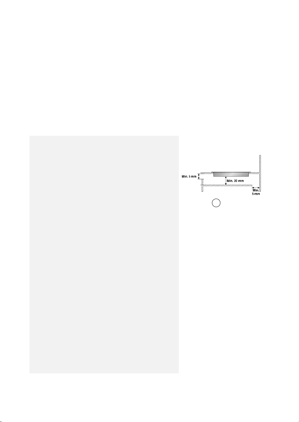
Hob
• The hob must be set into a worktop between 20 mm
and 50 mm deep.
• There must be nothing between the hob and the oven
(cross rails, brackets, etc.).
• The distance between the lower face of the glass
ceramic hob and the cupboard or separating panel
must be at least 20 mm.
• If the hob is to be installed next to a column unit, leave
a distance of at least 100 mm from the edge of the hob.
• Make an opening in the worktop of the dimensions shown in
the Product Description Sheet supplied separately.
• Apply the supplied gasket to the hob (unless it has already
been fitted), after having cleaned its surface.
Important
In order to prevent the electronic circuits from overheating, and
therefore from being damaged, we recommend the following:
• Do not install the hob near a dishwasher or washing
machine, so that the electronic circuits do not come
into contact with steam or moisture, which could
damage them.
If an oven (from our range of ovens) is installed beneath the hob,
make sure that it is equipped with a cooling system.
If the temperature of the electronic circuits exceeds the
maximum permitted temperature, the hob will switch off
automatically; in this case, wait for a few minutes until the
internal temperature of the electronic circuits reaches a tolerable
level, at which point it will be possible to switch the hob on again.
• Switch the hob off after use.
Front
A
Rear wall
69
INSTALLATION
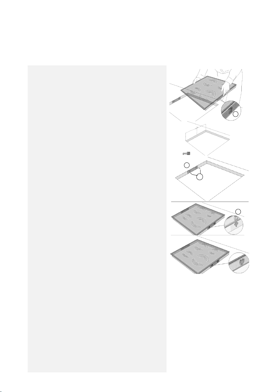
Assembly
A) If the worktop is made of wood, use the appropriate
brackets, spring clips and screws provided.
• Position the 4 clips (A), if not already fitted, around the hob
frame, in the slots provided, see Fig. 1.
• Measure the centre of the vertical sides of the cut-out as
shown in Fig. 2.
• Position the centre of the brackets (C) on the centre of the
side previously identified.
• The upper edge of the brackets must be flush with the
worktop surface.
• Secure by means of the 4 screws (B) provided, using the
pre-drilled holes.
• Insert the hob into the pre-prepared hole ensuring that the
clips (A) lodge into the bracket slots provided
(C Fig. 4 and 5).
Fig. 1
Fig. 3
A
Fig. 2
C
B
A
B) If the worktop is made of marble, ceramic, stone,
plastic materials, etc., order the installation kit, code
4812 310 19277 from an authorized after-sales service.
70
Fig. 4
Fig. 5
 Loading...