

Whirlpool AKT 477/IX INSTALLATION
AKT 477 PRODUCT DESCRIPTION SHEET
GB
FR
3 2
1
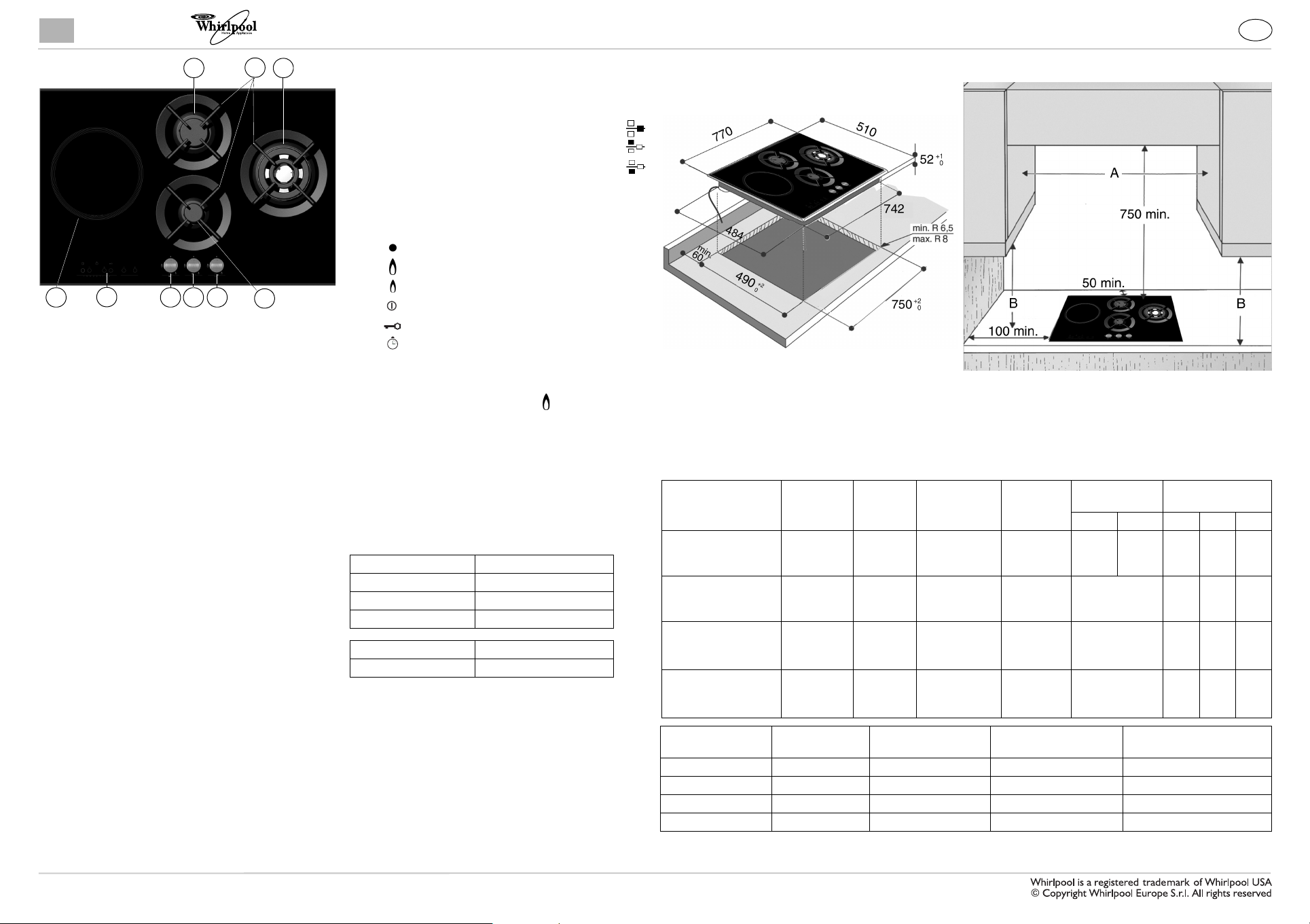
1. Removable panstand grids
2. 4-crown burner
3. Semi-rapid burner
4. Auxiliary burner
5. 4-crown burner control knob
6. Semi-rapid burner control knob
7. Auxiliary burner control knob
8. Induction zone control panel
9. Induction cooking zone
SYMBOLS
tap closed
Maximum flame
Minimum flame
9
8
57
6
4
Induction on/off
Induction key lock
Timer
USE OF THE GAS BURNERS
• To ignite one of the burners, turn the relative knob anti-clockwise to the maximum flame setting.
• Press the knob against the control panel to ignite the burner.
• After the burner has ignited, keep the knob pressed for about 5 seconds to allow the thermocouple to warm up.
This burner safety device shuts off the gas supply to the burner if the flame goes out accidentally (because of sudden
draught, an interruption in the gas delivery, boiling over of liquids, etc.).
• The device must not be pressed for more than 15 sec. If, after that time has elapsed, the burner does not
remain lit, wait at least one minute before trying to light it again.
- The burner might go out when the knob is released. This means that the thermocouple has not warmed up enough.
In this case, repeat the operations described above.
PRACTICAL ADVICE FOR USING THE GAS
BURNERS
For optimum burner performance, observe the following
rules:
- Use pots and pans that fit the burners (see table on the
right).
- Only use flat-bottomed pots and pans.
- Use the correct amount of water for cooking foods and
keep the pot covered.
Burner Pot Ø
Auxiliary 8 to 14 cm
Semi-rapid from 16 to 22 cm
4-crown from 24 to 26 cm
Induction zone Pot Ø
Ø 24 cm from 14 to 24 cm
PRACTICAL ADVICE FOR USING THE
INDUCTION COOKING ZONE
- Use only pots with the symbol “INDUCTION SYSTEM”
- For existing pots and pans, use a magnet to check
suitability: pots are unsuitable if they cannot be
magnetically detected
- Use pots and pans that fit the burners (see table on the
right)
DIMENSIONS AND DISTANCES TO BE MAINTAINED (mm)
NOTE: If the distance “A” between the wall cabinets is between 600 mm and 730 mm, the height “B” must be
a minimum of 520 mm.
If the distance “A” between the wall cabinets is greater than the width of the hob, the height “B” must
be a minimum of 400 mm.
In the event a hood is fitted above the hob, please refer to the hood assembly instructions for the
correct distance.
INJECTORS TABLE CATEGORY II2E+3+
Type of gas used Type of
NATURAL GAS
(Methane) G20
NATURAL GAS
(Methane) G25
LIQUEFIED
PETROLEUM GAS
(Butane) G30
LIQUEFIED
PETROLEUM GAS
(Propane) G31
Type of gas used Model
G20 20 mbar 3 burners 6.15 585 l/h 9.52
G25 25 mbar 3 burners 6.15 682 l/h 8.187
G30 28-30 mbar 3 burners 5.85 426 g/h 30.94
G31 37 mbar 3 burners 5.85 418 g/h 23.80
burner
4-crown
semi-rapid
auxiliary
4-crown
semi-rapid
auxiliary
4-crown
semi-rapid
auxiliary
4-crown
semi-rapid
auxiliary
configuration
Injector
marking
139
95
78
139
95
78
90
67
50
90
67
50
Rated thermal flow
rate kW
Rated thermal
flow rate
kW
3.50
1.65
1.00
3.50
1.65
1.00
3.20
1.65
1.00
3.20
1.65
1.00
Rated
consumption
333 l/h
157 l/h
95 l/h
388 l/h
183 l/h
111 l/h
233 g/h
120 g/h
73 g/h
229 g/h
118 g/h
71 g/h
Total rated consumption Air necessary (m3) for the
ELECTRICAL SUPPLY: 230 V ~ 50 Hz
ELECTRIC HOTPLATE POWER: 3000 W
Reduced heat
capacity kW
BE FR
1.95
0.45
0.35
1.55
0.35
0.30
1.55
0.35
0.30
1.55
0.35
0.30
1.55
0.35
0.30
combustion of 1 m
Gas pressure mbar
min. rat. max.
17 20 25
20 25 30
20 28-30 35
25 37 45
3
of gas
5019 319 01485
To get full satisfaction from the hob, please read these instructions carefully and keep them for future consultation.
USE OF THE INDUCTION COOKING ZONE
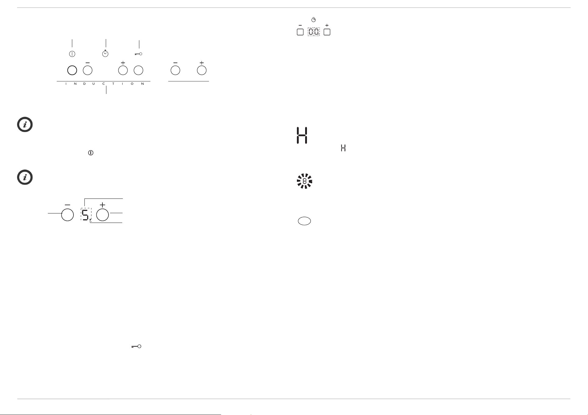
Control panel
On/Off Timer
Key lock
Timer
The timer can be used to set a max. cooking time of 99 minutes (1 hour and 39 minutes).
Set the desired time using buttons "+" and "-" of the timer function (see figure above). A few seconds after
the button is pressed, the timer begins the countdown (the luminous dot of the selected cooking zone
starts flashing). Once the set time has elapsed, an acoustic signal sounds and the cooking zone switches off
automatically.
To deactivate the timer, press the “-” button until the display shows “0:0” or press the “+” and “-” buttons of the timer at
the same time.
Minute minder
The minute minder can only be used when the hob is not in use and allows a maximum setting of 99 min.
Press the button “+” below the timer indicators: the display shows the minutes for setting.
Select the time desired using the buttons + and.
After a few seconds the minute minder starts to count down. Once the set time has elapsed an acoustic signal sounds.
Cooking zone controls and corresponding display
Control panel graphics shown in these instructions might not match exactly the graphics of your hob. Button's functions
are the same for all hob models.
Switching the hob ON/OFF
To switch the hob on, press the button for approx. 2 seconds until the cooking zone displays light up. To switch off, press
the same button until the displays switch off.
If the hob has been used, the residual heat indicator “H” remains activated until the induction cooking zone has cooled.
The hob automatically switches off if no function is selected within 10 seconds of switching on.
Switching on and adjusting cooking zone
Heat setting indicator
Button -
After switching on the hob and positioning the pot on the induction cooking zone, adjust the heat setting using the button +.
After pressing the + button, the display shows heat setting 5.
The cooking zone has different power levels that can be adjusted using the +/- buttons, going from “1”: min. heat setting to
“9”: max. heat setting. The fast boil function (Booster), is shown on the display with the letter “P”.
Fast boil function (Booster)
This function makes it possible to exploit the hob's maximum power (for example to bring water to the boil very quickly).
To select this function, press the button “+” unitl “P” appears on the display, or after switching the hob on, press the “-”
button. In this case too, “P” appears on the display. After 10 minutes' use of the booster function, the appliance automatically
sets the zone to level 9.
Button +
Selected cooking zone indicator
Switching off cooking zone
Select the cooking zone to be switched off by pressing the “+” or “-” key (a dot lights up at the bottom right hand side of the
heat setting indicator).
Press the key “-” to set the level to “0”.
The cooking zone can also be switched off by pressing “+” and “-” buttons at the same time. The cooking zone switches off
and the residual heat indicator “H” lights up
Key lock
This function locks the induction cooking zone controls to prevent accidental switching on by children. To activate the key
lock function, switch the hob on and hold the button for three seconds: an acoustic signal sounds and a led indicator lights
up below the key symbol to confirm activation. The control panel is locked with the exception of the OFF function. To unlock
the controls, repeat the key lock procedure. The illuminated dot switches off and the hob is active again.
The presence of cleaning water, liquid spilled from pots or any objects resting on the button below the symbol can accidentally
activate or deactivate the key lock function.
Important! The minute minder function can only be used when the hob is switched off; if it is then switched on, the minute
minder countdown is automatically cancelled.
Control panel indicators
Residual heat indicator.
The hob is fitted with a residual heat indicator for the induction cooking zone.
If the display shows , the cooking zone is still hot. If the residual heat indicator of a given cooking zone is lit, that zone can
be used, for example, to keep a dish warm or to melt butter.
When the cooking zone cools down, the display switches off.
Incorrect or missing pot indicator.
The hob features an automatic pot detection system. If no pot is detected, the display with the cooking zone power
level indicator flashes. Make sure the pot is correctly positioned and that it has the characteristics given in the section
“Before use”.
If no pot is detected after 60 seconds, the hob switches off.
REFERENCE TO LOCAL REGULATIONS
FR
The installation and maintenance of the appliance must be carried out by a qualified skilled technician in accordance with the
regulations in force, and in particular:
- Decree of 2 August 1977
Technical and Safety Rules applicable to fuel gas and liquefied hydrocarbon installations located within residential buildings and
outbuildings.
- Standard DTU P 45 - 204
Gas installations (formerly DTU no. 61-1 - Gas installations April 1982 + supplement no. 1 of July 1984).
- Departmental Health Regulations
For appliances connected to the mains electricity supply.
- Standard NF C 15-100
Low-voltage electrical installations - Standards.
Manufacturer:
Whirlpool Europe S.r.l.
Viale G. Borghi, 27
21025 Comerio (VA)
ITALY
 Loading...