

Whirlpool AKT 155 PRODUCT DESCRIPTION SHEET
AKT 155 PRODUCT DESCRIPTION SHEET
BG RO HR SL GB
2
1
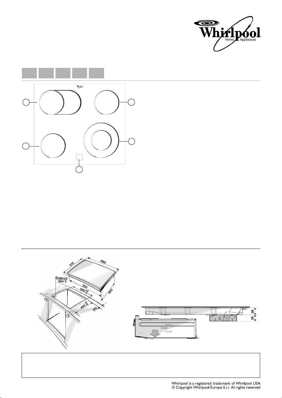
• To use the hob turn the knob(s) clockwise and position
it (them) on the required power setting or symbol
(each number/symbol corresponds to a different power
setting/function).
• To switch off the hob return the knob(s) to position “0”.
• Cooktop functions are explained in the separate “Oven
Product Description Sheet”.
N.B.: The cooling fan runs continuously at different
speed according to the temperature value of the
components when the cooktop or the oven are in use.
5
1. Radiant cooking zone Ø 145
3
4
2. Radiant oval dual cooking zone
3. Radiant cooking zone Ø 145
4. Radiant dual cooking zone Ø 210
5. Residual heat indicator lamps
The fan may continue to run for the time necessary to
ensure sufficient cooling of the components and
adjacent kitchen units after the appliances have been
switched off.
Important:
To avoid permanently damaging the glass-ceramic top,
do not use:
- Pots with bottoms that are not perfectly flat.
- Metal pots with enamelled bottom.
Any aesthetic defects (scratches, marks etc.) must be
reported at the time of installation.
DIMENSIONS OF COOKING HOB AND WORKTOP (mm)
Type PFEVS 230 V ~ 50 Hz 6.8 kW
5019 319 01074
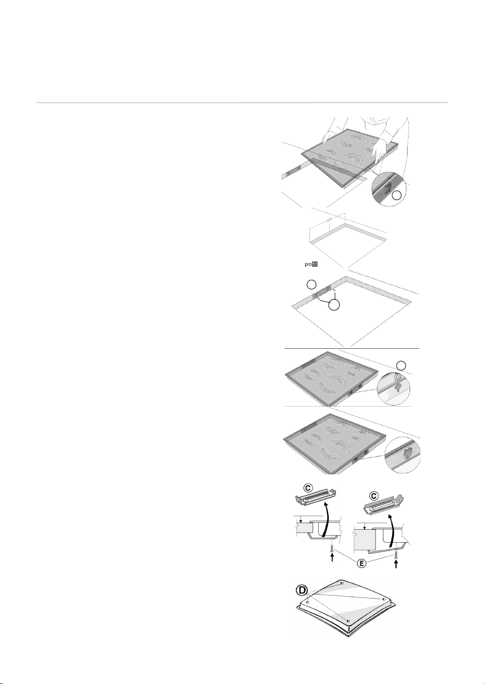
Assembly
A) If the worktop is made of wood, use the appropriate
brackets, spring clips and screws provided.
• Position the 4 clips (A), if not alreay fitted, around the
cooktop frame, in the slots provided, see Fig. 1.
• Measure the centre of the vertical sides of the cut out a
shown in Fig. 2.
• Position the centre of the brackets (C) on the centre of
the side previously identified.
• The upper edge of the brackets must be flush with the
worktop surface.
• Secure using the 4 screws (B) provided that should
screwed into the pre-prepared holes.
• Insert the cook hob into the pre-prepared hole ensuring
that the clips (A) lodge into the bracket slots provided
(C Fig. 4 and 5).
Fig. 1
Fig. 3
Fig. 4
A
Fig. 2
C
B
A
B) If the worktop is made of marble or other materials
(plastic compounds, ceramics, stone, etc.), the hob
must be fitted by means of brackets code 4819 310 18528
(to be ordered from After-Sales Service if not provided).
• Fit the hob into the worktop.
• Position the brackets (C) as shown in the figure, in
accordance with the thickness of the worktop.
• Secure the screws (E) in holes (D).
Fig. 5
Top min. 20 mm
Top max. 50 mm
 Loading...