


Whirlpool AKS 102 IX, AKS 101 NB, AKP 301 IX, AKP 300 WH, AKS 101 WH INSTALLATION Manual
...
10200157aGB.fm Page 3 Monday, September 5, 2005 3:53 PM
INSTALLING THE UNDER THE COUNTER
OVEN
Recommendations
Important: Disconnect the oven from the mains
before carrying out any installation work or
servicing.
Installation must be carried out by a qualified
•
technician in accordance with the manufacturer’s
instructions and in compliance with local
regulations.
Unpack the oven and make sure that the
•
appliance has not been damaged during transport
and that the oven door closes properly.
are not sure contact the dealer or the
nearest service centre.
After removing the oven from its packaging,
•
leave it on the polystyrene base to prevent it
from being damaged.
When installing the oven it is advisable to wear
•
protective gloves.
Do not lift the oven by the door handle. Get hold
•
of it using the side openings provided.
If you
Preparing the housing unit
Built-under oven
Kitchen units in contact with the oven must be
•
heat resistant (80 °C min).
Cut the kitchen unit and worktop to fit before
•
installing the appliances. Carefully remove any
shavings or sawdust that could prevent the
appliances from running properly.
The dimensions of the oven and unit are shown
•
in figures 1-2-3.
To allow for proper ventilation, an opening
•
should be left at the bottom of the housing unit.
Pay attention to the dimensions in Fig. 3.
Leave a minimum clearance of 5 mm between
•
the upper edge of the oven and the lower edge
of the worktop.
obstructed (Fig.2).
Make sure that the sides of the oven do not touch
•
the adjacent units.
If the kitchen unit is not securely fixed to the wall,
•
it must be anchored with standard brackets (G)
available on the market, see Fig. 3.
This clearance must never be
Cooktop
Caution:
than wood (e.g. plastic, ceramic, marble, stone,
etc.) remember to ask After Sales Service for the
fixing plates (Fig. 6-8).
•
•
•
•
•
•
Conventional electric cooktop
Important: remove any protective film before
installing the cooktop.
• If the worktop is made of wood, use the
1.
2.
• If the worktop is made of marble or other
1.
2.
to install the cooktop on surfaces other
The cooktop must be fitted in a worktop with a
minimum thickness of 20 mm and a maximum of
50 mm.
There must be nothing between the cooktop and
the oven (e.g. cables, insulating material, etc.).
An adjacent column unit must be installed at le ast
100 mm from the edge of the cooktop (Fig. 4).
Cut an opening in the worktop of the dimensions
given in the Product Description Sheet supplied
with the worktop.
We recommend you seal the internal edges of
the worktop with wood glue or silicone.
If not already in place, apply the supplied seal to
the cooktop, after cleaning the adhesive surface
thoroughly.
spring clips and screws provided.
Insert the 4 spring clips (B) (Fig. 5) in their
guides on the bottom of the cooktop.
Fit the cooktop into the worktop.
material (e.g. plastic, ceramic, marble, stone,
, the cooktop must be secured with special
etc.)
brackets (C) (Fig. 6), Code 4819 310 18528,
available from After Sales Service.
Fasten the brackets into the holes with the
screws provided.
Fit the cooktop into the worktop.
Glass-ceramic cooktop
Important: Remove any protective film before
installing the cooktop.
Make sure that that the opening in the worktop for
the cooktop is cut according to the dimensions
given in the drawing on the Product Description
Sheet. Pay attention to the tolerance range.
3
10200157aGB.fm Page 4 Monday, September 5, 2005 3:53 PM
The cooktop should not be forced into the
worktop. Forcing the glass-ceramic top may cause
it to crack (even at a later date)!
• If the worktop is made of wood
clips and screws provided (Fig. 7).
1.
Secure the spring clips (D) (Fig. 7) with the
screws provided (E) (Fig. 7) as shown, paying
attention to the specified distances.
2.
Fit the cooktop into the worktop.
• If the worktop is made of marble, plastic,
ceramic, stone, etc.
secured with special brackets (F) (Fig. 7), Code
4819 404 78697 available at After Sales Service.
1.
Fit the cooktop into the worktop.
2.
Place the 4 brackets (F) in position in
accordance with the thickness of the worktop
as shown in Fig. 8.
3.
Fasten the 4 screws (G) in the positions (H)
(Fig. 8).
, the cooktop must be
, use the spring
Electrical connection
Regulations require that the appliance be
earthed.
•
Connection to the mains must be carried out by
a qualified technician in accordance with the
manufacturer’s instructions and in compliance
with local regulations.
•
The installer is responsible for connecting
appliances correctly to the mains and for
observing the safety regulations.
•
The oven power cable must be long enough to
connect the built-in appliance to the mains.
•
Observance of safety directives requires that a
multi-pole switch with a minimum contact gap of
3mm be used for the installation.
•
Do not use multiple plug adapters or extension
leads.
•
After the oven has been installed, the electrical
components must be inaccessible.
Connecting the oven to the power
supply
•
Make sure that the voltage indicated on the rating
plate is the same as the mains voltage. The rating
plate is on the front edge of the oven (visible
when the door is open).
1.
Remove the two fastening screws of the
terminal box cover located on the bottom part
of the oven’s rear covering.
2.
Remove the cover to gain access to the terminal
box and insert the power cable (see table)
through the opening located on the bottom of
the oven.
3.
Connect the cable to the terminal box, tighten
the screws as far as they will go and secure it to
the cable fastener.
4
4.
Put the cover back on by inserting the two blades
in the slots and fasten it with the two screws.
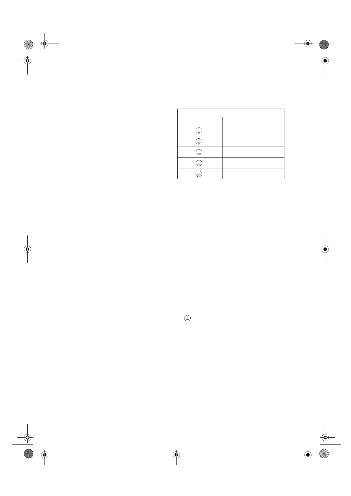
Power supply cable table
N° of conductors Type of cable
1N+
2+
2N+
3N+
3+
~
~
~
~
~
H05 RR-F 3 X 4 mm²
H05 RR-F 3 X 4 mm²
H05 RR-F 4 X 2.5 mm²
H05 RR-F 5 X 1.5 mm²
H05 RR-F 4 X 2.5 mm²
Interconnecting cooktop and oven
Important: do not connect the oven to the
power supply before you have finished
connecting the oven and cooktop.
•
Before connecting the oven to the power supply,
make sure that the cooktop is among the ones
listed in the cooktop/oven pairing product sheet
provided.
•
Remove the cover (L) (Fig. 9) (if present) of the
connectors (D) (Fig.9) located on the top covering
of the oven by loosening the fastening screw (M)
(Fig. 9). Lift up the cover (L) to gain access to the
connectors (D) and connect the connectors of the
cooktop (C) (Fig. 9) to the connectors of the oven
(D), matching the colours and alignment of the
housing guides visible on top of the connectors.
•
Then make the connection by pushing the
connectors all the way in, making sure that the
tongue clicks into place. Put the cover (L) back and
let the cables stick out from the bottom. Fasten
the cover with the screw removed previously.
•
Unscrew the nut of the ground screw (K) (Fig. 9)
on the top covering of the oven and insert
the yellow/green ground cable, leaving the
washer in place. Screw the nut back onto the
screw and tighten it as far as it will go.
Important:
correspond to the connection and colour
indications on the cooktop/oven connection plate
located at the top of the oven, request the adaptor
kit, code
Securing the oven
•
Lift up the oven getting hold of it by the openings on
the sides and insert it into the housing unit, being
careful not to trap the power supply cable (Fig.10).
•
Center the oven in the housing unit before
securing it.
•
Make sure that the plastic spacers (if provided)
are positioned correctly in the fastening holes.
Then anchor the oven to the housing unit with
the screws provided.
If the cooktop terminals do not
AMC 873
, from the After-sales Service.