

Page 1
31833061.fm Page 1 Monday, November 18, 2002 11:44 AM
AKR 400 - 404 - 410 - 437
AKR 501 - 521 - 645 - 934
PL
KARTA INSTALACYJNA
Minimalna odleg³oæ od palników: 60 cm (od palników elektrycznych), 70 cm (od
palników gazowych, olejowych lub wêglowych). Podczas monta¿u nale¿y
przestrzegaæ kolejnoci numeracji (1
pod³¹czaæ urz¹dzenia do zasilania, zanim nie zostanie zakoñczony ca³kowicie jego
monta¿.
POPIS INSTALACE
CZ
Minimální vzdálenost od sporákù: 60 cm (elektrické sporáky), 70 cm (sporáky na
plyn, naftu nebo uhlí). Pøi montái sledujte èíslování (1Ö2Ö3Ö.....) a pøísluné
pokyny. Spotøebiè pøipojte k elektrické síti a po úplném dokonèení instalace.
INTALAÈNÁ SCHÉMA
SK
Minimálna vzdialenost' od sporáka: 60 cm (elektrický sporák), 70 cm (plynový
sporák, sporák na naftu alebo uhlie). Pri montái postupujte pod¾a èíslic
(1Ö2Ö3Ö.....) a dodrujte prísluné pokyny. Spotrebiè nezapájajte do siete, kým nie
je intalácia úplne ukonèená.
H
ÜZEMBE HELYEZÉSI ÚTMUTATÓ
A tûzhelytõl való minimális távolság: 60 cm (elektromos tûzhely), 70 cm (gáz-, olaj-
vagy széntüzelésû tûzhely). A felszereléshez kövesse a számozást (1Ö2Ö3Ö.....)
és a vonatkozó utasításokat. A készüléket csak akkor szabad áram alá helyezni, ha
a beüzemelés már megtörtént.
Ö2Ö3Ö
.....) oraz odpowiednich instrukcji. Nie
СХЕМА УСТАНОВКИ
RUS
Минимальное расстояние до конфорок: 60 см (электрические конфорки),
70 см (газовые, керосиновые или угольные). Последовательность
действий при монтаже должна соответствовать нумерации (1
и приведенным инструкциям. Не подключайте прибор к сети до тех пор,
пока его установка не будет полностью закончена.
КАРТА ЗА ИНСТАЛИРАНЕ
BG
Минимално разстояние от печки: 60 см (електрически печки), 70 см
(печки с газ, нафта или въглища). За монтаж следвайте номерацията
(1Ц2Ц3Ц.....) и съответните инструкции. Не включвайте захранването на
уреда, докато инсталирането не е завършено докрай.
RO
FIªA DE INSTALARE
Distanþa minimã de la arzãtoare: 60 cm (arzãtoare electrice), 70 cm (arzãtoare pe
bazã de gaze, petrol sau cãrbune). Pentru montare urmaþi numerotarea
Ö2Ö3Ö
(1
pânã când nu terminaþi definitiv operaþia de instalare.
GB
INSTALLATION SHEET
.....) ºi instrucþiunile corespunzãtoare. Nu branºaþi aparatul la curent
Ö2Ö3Ö
Minimum height above cooker: 60 cm (electric cookers), 70 cm (gas, oil-fired or
coal cookers). To assemble follow the numbers (1Ö2Ö3Ö.....) and relative
instructions. Do not connect the appliance to the electrical power supply until
installation is completed.
.....)
5019 318 33061
Page 2
31833061.fm Page 2 Monday, November 18, 2002 11:44 AM
AKR 400 - 404 - 410 - 437
AKR 501 - 521 - 645 - 934
A - Wersja zasysaj¹co -
wyci¹gowa
A - Provedení s nasáváním
A - Verzia s odvodom vzduchu
Beszívós változat (A)
А - Исполнение с
всасыванием
A - Вариант с аспириране
A - Versiune aspirantã
A - Extractor version
B - Wersja z recyrkulacj¹
powietrza (filtrowanie)
B - Provedení s filtrací
B - Verzia s recirkuláciou
vzduchu
Szûrõs változat (B)
B - Исполнение с
фильтрацией
B - Вариант с
филтриране
B - Versiune filtrantã
B - Filter version
Zainstalowaæ filtr z wêgla aktywnego
Instalace uhlíkového filtru
Namontujte uhlíková filter
Szerelje be a szénszûrõt
Установка угольного фильтра
Инсталирайте въгленовия
филтър
Instalarea filtrului pe bazã de
cãrbune
Fit the carbon filter
5019 318 33061
Page 3

31833061.fm Page 10 Monday, November 18, 2002 11:44 AM
AKR 400 - 404 - 410 - 437
AKR 501 - 521 - 645 - 934
1. Control panel.
2. Self-supporting grease filters
(depending on model).
3. Extractor grille with internal grease filter
(depending on model).
4. Lighting unit.
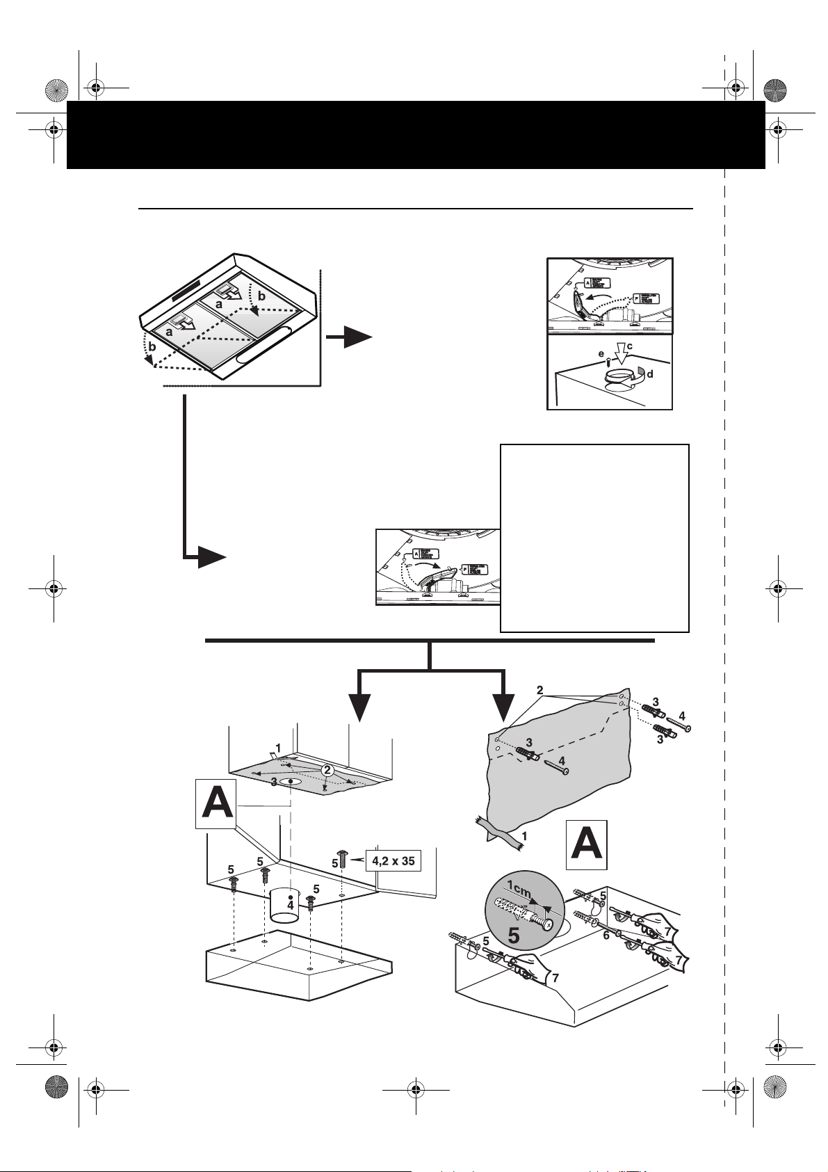
Bulb maintenance
1. Disconnect the electrical power supply.
2. Open the extractor grille or remove the self-
supporting grease filter (depending on model).
Fig. 1 (a-b).
3. Remove the burnt-out bulb.
Replace using 40 W max E14 bulbs only.
4. Refit the extractor grille or grease filter.
Fitting or renewing the carbon filter:
1. Disconnect the electrical power supply.
2. Open the extractor grille or remove the self-
supporting grease filter (depending on model).
Fig. 1 (a-b).
3. To access the carbon filter seat, rotate the knobs
90° and open the lid. Fig. 2 (c).
4. Fit the shaped carbon filter in its default
location. Fig. 2 (d).
5. Turn the carbon filter locking knob 90° (check
that the filter is secured, otherwise rotate it
further). Fig. 2 (e).
6. Close the carbon filter compartment
7. Refit the extractor grille or grease filter.
To remove the carbon filter, proceed in reverse order.
Grease filter maintenance:
1. Disconnect the electrical power supply.
2. Open the extractor grille or remove the self-
supporting grease filter (in this last case wash
the filter immediately). Fig. 1 (a-b).
3. Remove the device securing the grease filter.
4. Remove the dirty grease filter.
5. After the grease filter has been replaced or
cleaned (depending on model), refit the parts in
reverse order, making sure the entire extraction
surface is covered.
PRODUCT SHEET
Fig. 1
CONTROL PANEL
Light switch.
The switch has two positions
(lights OFF - lights ON).
To switch on the lights: move the switch to the
right.
Extraction speed selection switch.
The extraction speed switch has different
settings, depending on the amount of steam and
fumes.
To increase the extraction speed: move the
switch to the right.
Valve open/close switch (only AKR 645):
move the switch to the right to open the valve
and extract steam and fumes (the hood must be
connected to a peripheric extractor unit).
5019 318 33061
CZ
PL SK H RUS
Fig. 2
BG RO GB
 Loading...