

Page 1
31833101.fm Page 1 Friday, November 7, 2003 12:10 PM
AKR 400 - 404 - 405 - 410 - 437 - 501 - 521
AKR 645 - 934 - 417 - 948 - 961 - 978
S
INSTALLATIONSBLAD
Minsta tillåtna avstånd från olika typer av spisar: 60 cm (elektrisk spis), 70 cm
(gasspis, gasolspis eller koleldad spis). Följ givna anvisningar och
nummerordningen (1Ö2Ö3Ö.....) när fläktkåpan skall monteras. Slå inte på
strömmen till fläktkåpan förrän installationen är helt avslutad. Observera! AKR
961 skall fästas på väggen och har ett utdragbart rökrör (se det extra
informationsbladet för montering av rökröret).
N
INSTALLASJONSVEILEDNING
Minimumsavstand til komfyrtopp: 60 cm (elektriske kokeplater), 70 cm (gass-,
parafin- eller kullkomfyr). Følg nummereringen ved montering (1Ö2Ö3Ö.....),
samt monteringsanvisningene. Apparatet må ikke tilkobles strømnettet før
installasjonen er helt avsluttet. Advarsel: Modellen AKR 961 skal festes til
veggen og er utstyrt med en teleskopisk avtrekkskanal (se medfølgende
monteringsveiledning for avtrekkskanalen).
DK
INSTALLATIONSVEJLEDNING
Minimumafstand fra kogezoner: 60 cm (elkogezoner), 70 cm (gas-, olie- eller
kulfyrede kogezoner). Ved montering skal man følge vejledningens
nummerrækkefølge (1Ö2Ö3Ö.....) og de tilhørende instruktioner. Apparatet
må ikke tilsluttes elforsyningen, før installationen er fuldført. Bemærk: Model
AKR 961 skal fastgøre til muren og er udstyret med en teleskopisk aftrækskanal
(se det medfølgende ark vedrørende montering af aftrækskanalen).
FIN
ASENNUSOHJEET
Vähimmäisetäisyys liedestä: 60 cm (sähköliesi), 70 cm (kaasu-, öljy- tai
hiililiedet). Suorita asennus numerojärjestyksessä (1Ö2Ö3Ö.....) ohjeiden
mukaisesti. Älä kytke liesituuletinta sähköverkkoon ennen kuin kaikki
asennusvaiheet on suoritettu. Huomio: malli AKR 961 kiinnitetään seinään ja
siihen kuuluu teleskooppihormi (hormin asennusohjeet lisälehtisessä).
GB
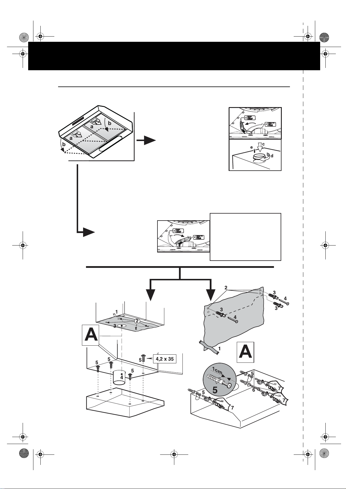
INSTALLATION SHEET
Minimum height above cooker: 60 cm (electric cookers), 70 cm (gas, oil-fired or
coal cookers). To assemble follow the numbers (1Ö2Ö3Ö.....) and relative
instructions. Do not connect the appliance to the electrical power supply until
installation is completed. Warning: models AKR 961 and AKR 978 are fitted to
the wall and are equipped with a telescopic flue (to assemble the flue see
attached instructions sheet).
5019 318 33101
Page 2
31833101.fm Page 2 Friday, November 7, 2003 12:10 PM
AKR 400 - 404 - 405 - 410 - 437 - 501 - 521
AKR 645 - 934 - 417 - 948 - 961 - 978
A - Utblåsningsfläkt
A - Utblåsningsversjon
A - Model med aftræk
A - Imevä malli
A - Extractor version
B - Filterfläkt
B - Filterversjon
B - Model med kulfilter
B - Suodattava malli
B - Filter version
Montera kolfiltret
Installering av kullfilteret
Monter kulfilteret
Asenna hiilisuodatin
Fit the carbon filter
5019 318 33101
Page 3
31833101.fm Page 7 Friday, November 7, 2003 12:10 PM
AKR 400 - 404 - 405 - 410 - 437 - 501 - 521
AKR 645 - 934 - 417 - 948 - 961 - 978
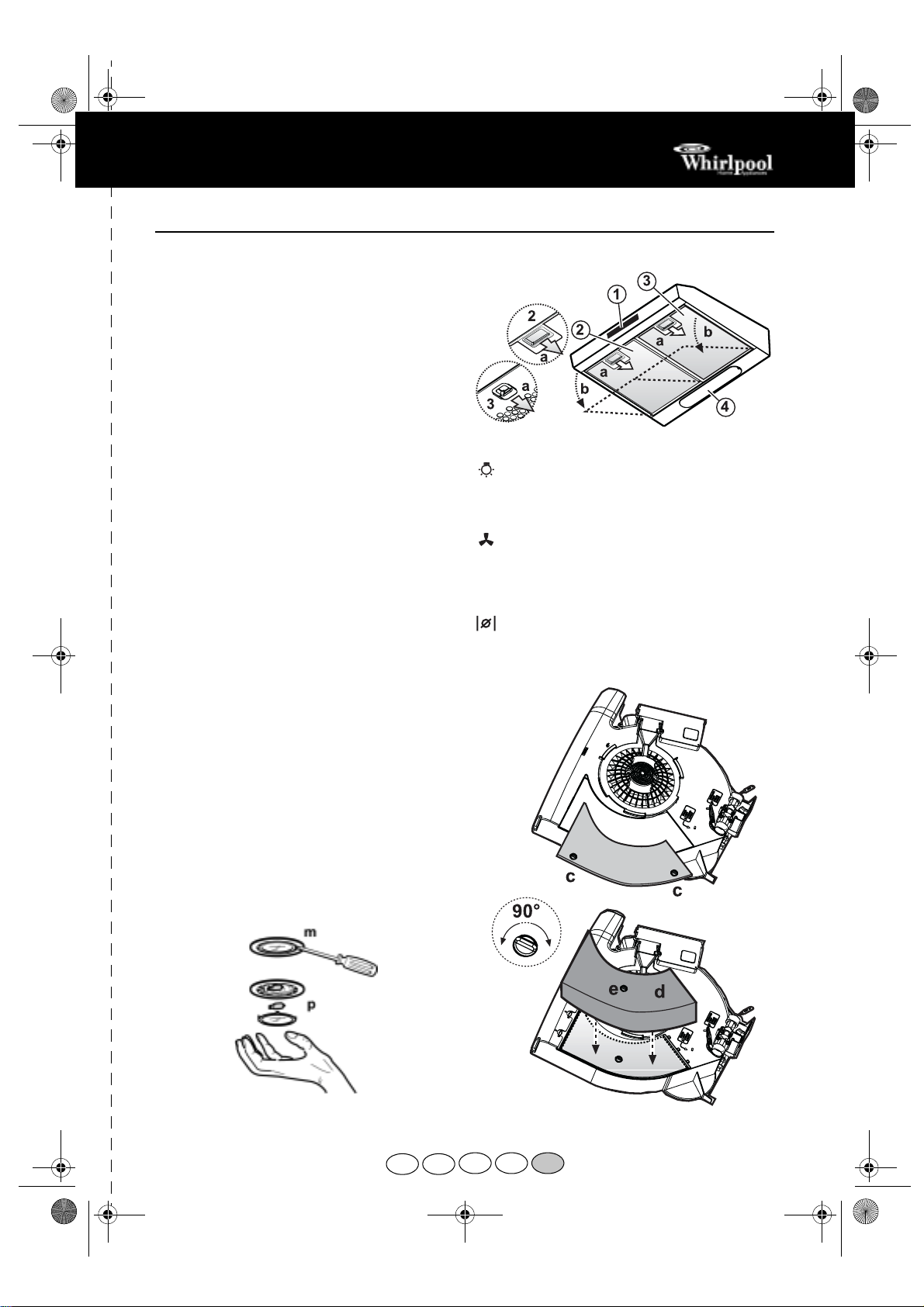
1.
Control panel.
2.
Self-supporting grease filters
(depending on model).
3.
Extractor grille with internal grease filter
(depending on model).
4.
Lighting unit.
Replacing bulbs
1.
Disconnect the electrical power supply.
2.
Open the extractor grille or remove the selfsupporting grease filter (depending on model).
Fig. 1 (a-b)
3.
Remove the burnt-out bulb.
Replace using 40 W max E14 bulbs only.
4.
Refit the extractor grille or grease filter.
Only for model equipped with halogen bulbs
Use a small screwdriver or any other suitable tool to
prise off
Replace the damaged bulb.
Use 20 W ma x halogen bulbs only, making sure not to
touch them with your hands. Close the lighting unit
(snap-close).
.
(m-Fig. 3)
the lamp cover
(p-Fig. 3).
Fitting or renewing the carbon filter:
1.
Disconnect the electrical power supply.
2.
Open the extractor grille or remove the selfsupporting grease filter (depending on model).
Fig. 1 (a-b)
3.
To access the carbon filter seat, rotate the knobs
90° and open the lid.
4.
Fit the shaped carbon filter in its default
location.
5.
Turn the carbon filter locking knob 90° (check
that the filter is secured, otherwise rotate it
further).
6.
Close the carbon filter compartment
7.
Refit the extractor grille or grease filter.
To remove the carbon filter, proceed in reverse order.
.
Fig. 2 (d)
Fig. 2 (e)
Fig. 2 (c)
.
.
.
Grease filter maintenance:
1.
Disconnect the electrical power supply.
2.
Open the extractor grille or remove the selfsupporting grease filter (in this last case wash
the filter immediately).
3.
Remove the device securing the grease filter.
4.
Remove the dirty grease filter.
5.
After the grease filter has been replaced or
cleaned (depending on model), refit the parts in
reverse order, making sure the entire extraction
surface is covered.
Fig. 1 (a-b).
PRODUCT SHEET
CONTROL PANEL
Light switch.
The switch has two positions
(lights OFF - lights ON).
To switch on the lights: move the switch to the
right.
Extraction speed selection switch.
The extraction speed switch has different
settings, depending on the amount of steam and
fumes.
To increase the extraction speed: move the
switch to the right.
Valve open/close switch
(only AKR 645):
open the valve and extract steam and fumes (the
hood must be connected to a peripheric extractor
unit).
Fig. 1
move the switch to the right to
5019 318 33101
Fig. 3
S N
Fig. 2
DK FIN GB
 Loading...