

SERVICE
Model AKP 511/WH
Version 8577 511 15050 Page
Whirlpool Europe
Customer Services
AKP 511/WH
Service Manual
Built-in oven
AKP 511/WH
Technical data 2
Spare part list 3
Exploded view 4
Wiring diagram 5
This documentation is only intended for qualified technicians who are aware of the respective safety regulations.
Date: 06.08.1996 Subject to modification
Document-No.: 4812 715 14372
06.08.1996 / Page 2 Whirlpool Europe
Doc. No: 4812 715 14372 Customer Service
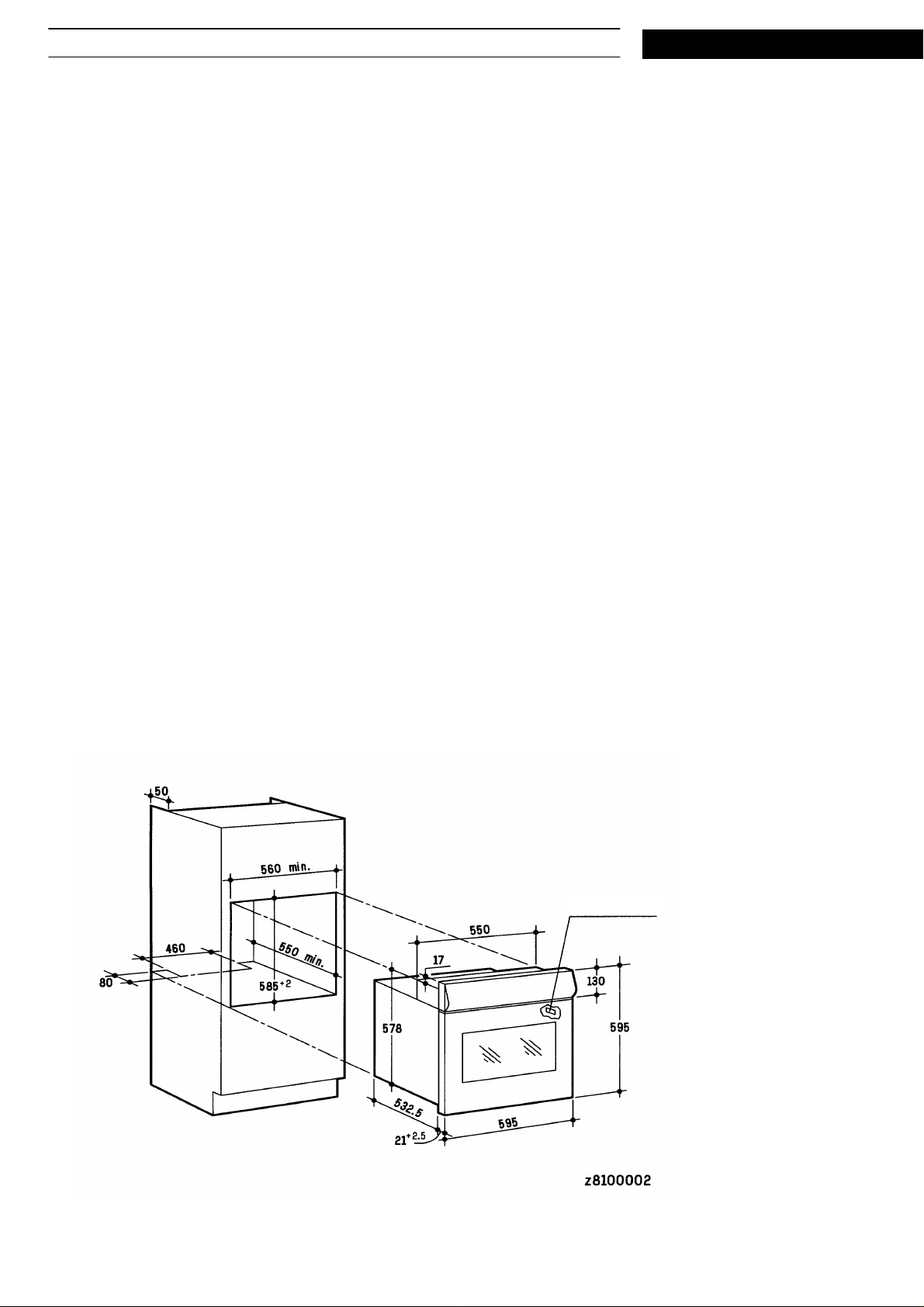
Technical data
Electrical connection
Rated voltage 240V ~
Main connection 380-400V 3N~ 50 Hz
380-400V 2N~ 50 Hz
220-230V 1N~ 50 Hz
Power usable contemporaneously 2550 W
Upper heating element 900 W
Lower heating element - W
Forced air 2000 W
Grill heating element (variable) 2450 W
Electrical components
Minute minder DAC 88C 0018
Hob control -
SERVICE
Accessories
Baking tray - mm
Pan set enameled 415,0 x 318,0 mm
Grid chrome 446,5 x 340,0 mm
Service sticker

Whirlpool Europe 06.08.1996 / Page 3
SERVICE
Customer Service Doc. No: 4812 715 14372
Spare part list
Model AKP 511/WH
Service No. 857751115050
Version 857751115050
Pos. No. 12NC Code Description from to
025 1 4819 460 89312 Trim, side right
025 2 4819 460 89313 Trim, side left
041 0 4819 417 19457 Hinge
045 0 4819 466 89197 Hinge run.mech.
111 0 4819 498 78019 Handle,door
121 0 4819 442 38353 Innerdoor,oven
141 0 4819 450 69855 Oven glass
191 0 4819 468 18109 Gasket
201 0 4819 442 38093 Plate
232 0 4819 460 89445 Trim
245 0 4819 458 19992 Oven shelf
245 2 4819 458 19538 Grid
247 1 4819 395 48003 Plier grid
247 2 4819 418 38328 Fat pan
261 0 4819 458 19999 Grid left
261 1 4819 458 19998 Grid right
301 0 4819 453 58072 Control panel
301 3 4819 460 89421 Trim, lower
301 4 4819 453 58257 Panel
334 1 4819 411 29132 Knob thermostat
334 2 4819 411 29131 Knob
334 5 4819 411 29133 Knob,regulation
354 0 4812 134 48021 Pilot lamp
354 1 4819 462 79749 Lens red
354 4 4819 462 38759 Guide pilot lamp
360 0 4819 282 18665 Timer
361 0 4819 410 28709 Button,push
440 0 4819 361 78231 Fan
441 0 4819 361 18374 Motor,fan
441 1 4819 468 18099 Gasket
443 0 4819 515 28115 Fan wheel
451 0 4819 259 28823 Heating element
452 0 4819 259 28824 Heating element
493 0 4819 290 68363 Terminal block
523 0 4819 273 28135 Regulator 1 zone
554 0 4819 282 28603 Thermostat
557 0 4819 282 28564 Thermostat
562 0 4819 252 28088 Thermal fuse
620 9 4819 273 28401 Switch,oven
651 0 4819 134 88153 Lamp,oven
652 0 4819 255 18214 Holder,lamp
652 1 4819 450 69844 Lamp screen
914 0 4819 505 18323 Nut
915 0 4819 505 18145 Nut
932 0 4819 492 68714 Spring
993 0 4819 310 39087 Mounting kit

06.08.1996 / Page 4 Whirlpool Europe
Doc. No: 4812 715 14372 Customer Service
Exploded view
SERVICE

SERVICE
Wiring diagram
Whirlpool Europe 06.08.1996 / Page 5
Customer Service Doc. No: 4812 715 14372
 Loading...