

Page 1

OPERATING INSTRUCTIONS
DESCRIPTION OF PRODUCT AND SYMBOLS
LIGHTING THE BURNERS
PRATICAL ADVICE FOR USING THE BURNERS
GRID POSITIONING
DIMENSIONS AND DISTANCES TO BE RESPECTED
(mm)
INJECTORS TABLE
PRECAUTIONS AND GENERAL
RECOMMENDATIONS
PROTECTING THE ENVIRONMENT
INSTALLATION (FLUSH OR SEMI-FLUSH)
GAS CONNECTION
ELECTRICAL CONNECTION
FIXING TO THE SUPPORT STRUCTURE -
CONVENTIONAL FITTED MODEL (SEMI-FLUSH)
FIXING TO THE SUPPORT STRUCTURE -
FLUSH-MOUNTING MODEL
ADJUSTMENT TO DIFFERENT TYPES OF GAS
REPLACING INJECTORS
COCK MINIMUM SETTING ADJUSTMENT
CARE AND MAINTENANCE
CARE AND CLEANING OF HOB COMPONENTS
TROUBLESHOOTING GUIDE
AFTER-SALES SERVICE
17
Page 2
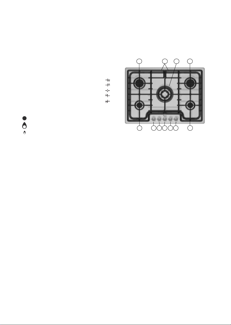
DESCRIPTION OF PRODUCT AND SYMBOLS
Removable panstand grids
1.
Auxiliary burner
2.
Semi-rapid burner
3.
4 ring burner
4.
Semi-rapid burner
5.
Auxiliary burner
6.
Auxiliary burner control knob
7.
Semi-rapid burner control knob
8.
4-crown burner control knob
9.
Semi-rapid burner control knob
10.
Auxiliary burner control knob
11.
Symbols
tap closed
Maximum flame
Minimum flame
3 1 4 5
11 10 9 8 7
2 6
LIGHTING THE BURNERS
Turn the corresponding knob anticlockwise to
1.
the max. flame symbol.
Press the knob against the control panel to
2.
ignite the burner.
After the burner has ignited, keep the knob
3.
pressed for about 5 seconds to allow the
thermocouple to warm up.
This safety device shuts off the gas if the flame
goes out accidentally (draughts, interruption of
gas, liquids boiling over, etc.).
18
The device must not be pressed for more than
15 sec. If, after that time has elapsed, the
burner does not remain lit, wait at least one
minute before trying to light it again.
The burner might go out when the knob is
released. This means that the thermocouple
has not warmed up enough. In this case,
repeat the operations described above.
Page 3
PRATICAL ADVICE FOR USING THE
BURNERS
For optimum burner performance, observe the
following rules:
Use pots and pans that fit the burners (see table
•
on the right).
Only use flat-bottomed pots and pans.
•
Use the correct amount of water for cooking
•
foods and keep the pot covered.
Do not use pots and pans that protrude over the
•
edge of the hob
Do not use:
Two burners at the same time with only one pot
•
(e.g. fish kettle).
Important:
Do not place and/or drag the grids upside down on
the hob as they could scratch it.
Burner Pot Ø
wok
semi-rapid
auxiliary
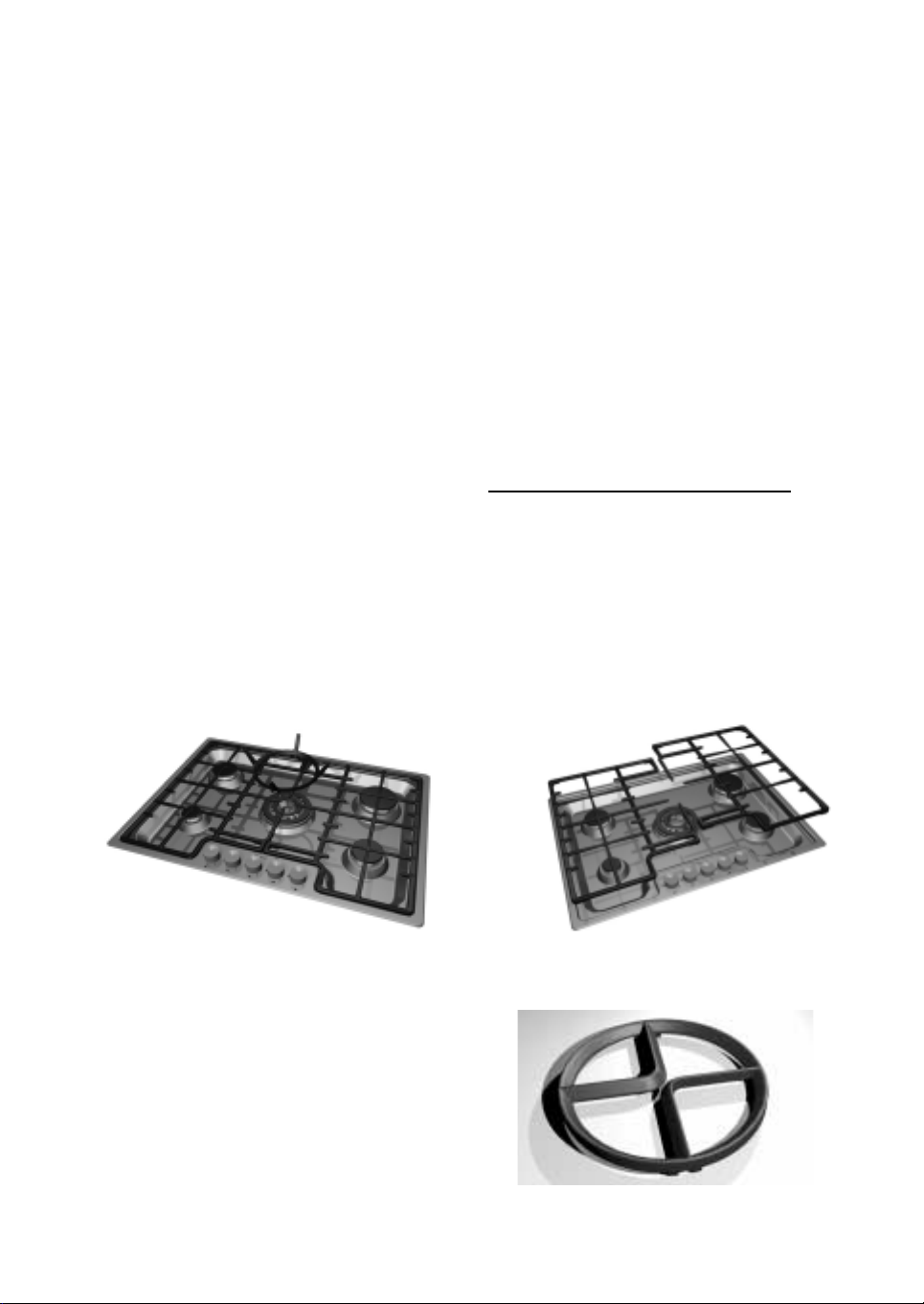
GRID POSITIONING
Position the grids and WOK pot adapter as shown in the following figure.
from 24 to 26 cm
from 16 to 22 cm
8 to 14 cm
To avoid deterioration of the hob, it is provided with a raised grid for placing under pots wider than 26 cm.
19
Page 4
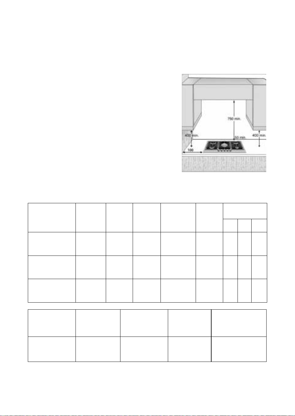
DIMENSIONS AND DISTANCES
TO BE RESPECTED (mm)
In case of installation of a hood above the cooktop, please
refer to the hood instructions for the correct distance.
INJECTORS TABLE
INJECTOR TABLE CATEGORY: II2H3+ IT + UK
Typ e o f g as us ed
NATURAL GAS
(Methane) G20
LIQUEFIED
PETROLEUM GAS
(Butane) G30
LIQUEFIED
PETROLEUM GAS
(Propane) G31
Typ e of
burner
4 ring
semi-rapid
auxiliary
4-crown
semi-rapid
auxiliary
4-crown
semi-rapid
auxiliary
Injector
marking
139
95
78
95
67
50
95
67
50
Rated
thermal
flow rate
kW
3.50
1.65
1.00
3.50
1.65
1.00
3.50
1.65
1.00
Rated
consumption
333 l/h
157 l/h
95 l/h
254 g/h
120 g/h
73 g/h
250 g/h
118 g/h
71 g/h
Reduced
heat
capacity
kW
1.55
0.35
0.30
1.55
0.35
0.30
1.55
0.35
0.30
Gas pressure
mbar
min. rat. max.
17 20 25
25 30 35
25 30 35
Typ e of g as us ed
G20 20 mbar
G30 28-30 mbar
G31 37 mbar
ELECTRIC SUPPLY: 230 V ~ 50 Hz
20
Model
configuration
4 burners
4 burners
4 burners
Rated thermal
flow rate
kW
8.80
8.80
8.80
Total rated
consumption
837 l/h
640 g/h
628 g/h
Air necessary (m
for the combustion
3
of 1 m
of gas
9.52
30.94
23.80
3
)
Page 5

PRECAUTIONS AND GENERAL
RECOMMENDATIONS
To get full satisfaction from your hob, please
read these instructions carefully and keep
them for future consultation.
These instructions are only valid for those
•
Countries where the destination abbreviations
are mentioned on the product description sheet
and on the hob.
Keep the packing elements (plastic bags,
•
polyurethane foam, etc.) out of the reach of
children, as they are a potential source of danger.
• Make sure the hob was not damaged during
transport and remove any protective film
from the appliance parts.
• This hob (Class 3) is designed solely for
household use for cooking food. Any other
use (such as heating rooms) is to be
considered improper and, as a consequence,
dangerous.
• This appliance must not be used by persons
(including children) with physical, sensorial
or mental impairment, unless supervised or
previously instructed in its use by those
responsible for their safety.
• Make sure the installation and gas/electrical
connections are carried out by a qualified
technician in compliance with the current
local regulations.
• This appliance should only be installed and
used in well-ventilated rooms, in
accordance with current regulations.
Carefully read the instructions before
installing and using this appliance.
• Gas adjustment and supply pressure are
indicated on the rating plate located under
the hob. If another type of gas is to be used,
refer to the section “Conversion to different
types of gas”.
21
Page 6

PROTECTING THE ENVIRONMENT
Packaging
The packing material is entirely recyclable and is
marked with the recycling symbol , identifying it
as a type of material that must be sent to local waste
disposal centres.
Product
This appliance is marked in compliance with
European Directive 2002/96/EC on Waste
Electrical and Electronic Equipment (WEEE). By
ensuring that this appliance is scrapped suitably, you
can help prevent potentially damaging
consequences for the environment and health.
The symbol on the product or accompanying
documentation indicates that this product should
not be treated as domestic waste but must be taken
to a suitable centre for collection and recycling of
electrical and electronic equipment. Disposal must
be carried out in accordance with local
environmental regulations for waste disposal.
For further information on the treatment, recovery
and recycling of this product, contact the
competent local authority, the domestic waste
collection service or the shop where you purchased
the appliance.
Declaration of conformity
This cooking hob has been designed,
constructed and marketed in conformity with
the following:
safety requirements of EEC "Gas" Directive
•
90/396.
safety requirements of EEC “Low voltage”
•
Directive 2006/95/EC (which
replaces 73/23/EEC as amended).
protection requirements of EEC “EMC”
•
Directive 89/336.
requirements of EEC Directive 93/68.
•
This cooking hob is suitable for contact with
foodstuffs, and complies with Regulation (EC)
no. 1935/2004.
Notes:
Improper use of the grids could scratch the hob.
•
Do not position the grids upside down or drag
them across the hob.
In case of prolonged use, additional ventilation
•
may be needed (opening a window or increasing
the extraction force of the hood).
Warning
• Keep children away from the hob when in
use and do not let them play with the knobs
or any other part of the appliance.
• The protective rubber feet under the grids
represent a choking hazard for young
children if swallowed.
• After removing the grids, make sure all the
rubbers are correctly fitted.
• After using the hob, always make sure the
control knobs are turned off and close the
main cock of the gas supply pipe or cylinder.
22
Page 7

INSTALLATION (FLUSH OR SEMI-FLUSH)
the outer surfaces of the furniture or applianc es
Technical information for the installer
Be careful:
people are needed during installation.
This product can be fitted in a 20 to 50 mm thick
•
worktop.
If an oven is not provided for under the hob,
•
insert a separating panel of size at least equal to
the opening in the worktop. This panel must be
positioned not more than 150 mm from the
upper surface of the worktop, and never less
than 50 mm from the bottom of the hob.
If there is an oven beneath the hob, make sure
•
that it is manufactured by Whirlpool and
equipped with a cooling system.
manufacturer declines all liability if another
brand oven is installed beneath the hob.
Before installation, make sure that:
The local gas supply (type and pressure) and hob
•
settings are compatible (see the dataplate and
injector table).
Given the weight of the product, two
The
•
adjacent to the hob are heat resistant according
to local regulations.
combustion products are discharged outdoors
•
through specific hoods or wall and/or window
mounted electrical fans.
continuous natural air circulation is ensured
•
through a sufficient opening in the wall of at least
2
100 cm
- Permanent and in walls to the outside of the
- Made in such a way that it cannot be
- Protected by plastic grilles, metal mesh, etc.,
- Located near the floor and positioned so as not
. This wall opening must be:
room;
obstructed from the inside or outside (even
accidentally);
which do not reduce the above-mentioned
useful area;
to interfere with the operation of the fume
exhaust devices.
23
Page 8

GAS CONNECTION
The gas supply system must comply with local
regulations.
The section “national regulations" gives the specific local
•
regulations for the country of use.
If no information concerning your Country is given, please ask
•
your installer for details.
The connection of the hob to the gas pipe network or gas
•
cylinder must be made by means of a rigid copper or steel
pipe with fittings complying with local regulations, or by
means of a continuous-surface stainless steel hose complying
with local regulations. The maximum length of the hose is 2
linear metres.
Before connecting the tube to the elbow (A), fit the gasket (B)
•
supplied, in compliance with
Be careful:
so as not to touch any mobile part of the furniture. It must pass
through an area free of any hindrances and the entire length of
the hose must be accessible for inspection.
After connection to the gas supply, check for leaks with soapy
•
water.
if a stainless steel hose is used, it must be installed
EN 549
.
ELECTRICAL CONNECTION
The electrical connections must comply with the local
regulations.
The data relevant to the voltage and power absorption are
•
indicated on the rating plate.
The earthing of this appliance is compulsory by law.
•
When installing, provide for an omnipolar cutout switch with
•
contact opening distance of at least 3 mm.
If the power cable needs replacing, use one having the same
•
characteristics as the original supplied standard (type
H05V2V2-F T90°C or H05RRF). This operation must be
performed by the After-Sales Service.
Do not use extension leads.
•
• The manufacturer declines any liability for possible
damage or injury due to non-compliance with the
above-mentioned rules.
L
Earth
(Yellow/Green)
N
24
Page 9

FIXING TO THE SUPPORT STRUCTURE CONVENTIONAL FITTED MODEL
(SEMI-FLUSH)
Important: The following operation must be carried out
by a competent technician. Installation can be carried out
on different materials: such as masonry, metal, solid wood
and plastic laminated wood provided it is heat resistant (T
90°C).
Make an opening in the top, of the dimensions shown in fig. 1.
Carefully apply the insulating sealing strip (supplied) around the
outside edge of the hob as shown in the figure below, pressing
lightly to make it adhere (Fig. 2).
Fig. 1
Fix the hob with the special brackets supplied.
The supply includes 2 types of brackets:
- 7 of standard length (Service Code 4812 404 49874) for
installation on kitchen tops thicker than 4 cm
- 7 longer than standard (Service Code 4812 404 49875) for
installation on kitchen tops less than 4 cm thick
The brackets must be fixed with the special screws, to the front
(4) and the back (3) using the seats on the bottom of the hob
(Fig. 3).
Be careful: The power cable must be long enough to allow the
hob to be removed upwards.
Fig. 2
Fig. 3
25
Page 10

FIXING TO THE SUPPORT STRUCTURE FLUSH-MOUNTING MODEL
Important: The following operation must be
carried out by a competent technician.
Installation can be carried out on different
materials such as masonry, metal, solid wood
and plastic laminated wood provided it is heat
resistant (T 90°C).
Make an opening in the cabinet top, of the dimensions
shown in fig. 1; to correctly install the hob a 2 mm
deep milling must also be made in the top (Fig. 4).
In case of laminated tops less than 2 mm thick, carry out the
Note:
milling in the cabinet as shown in the diagram (detail).
Before positioning the hob, apply the adhesive sealing strip
(supplied) on the entire bottom surface that will be in contact
with the top (fig. 2).
Carry out these operations:
Place the hob on the milling and, using the screws and brackets
•
supplied, fix it to the support structure, ensuring that it is
perfectly flat (fig. 3).
Carefully trim the excess sealing strip (fig. 4). In case of
•
installation on wood (especially chipboard), if there are small
spaces between the milling and the edge of the hob, fill with
minimum amounts of silicone. The bottom part of the casing
must be entirely accessible after installation.
Important:
Tighten (lightly by hand) the brackets fixing the hob to the
•
cabinet.
If the cabinet worktop is in wood or similar, protect the edge
•
of the milling with a primer before closing with the sealing strip.
Fix the hob with the special brackets supplied.
The supply includes 2 types of brackets:
- 7 of standard length (Service Code 4812 404 49874) for
installation on kitchen tops thicker than 4 cm
- 7 longer than standard (Service Code 4812 404 49875) for
installation on kitchen tops less than 4 cm thick
The brackets must be fixed with the special screws, to the front
(4) and the back (3) using the seats on the bottom of the hob (Fig.
3).
Be careful: The power cable must be long enough to allow the
hob to be removed upwards.
Fig. 5
Fig. 6
Fig. 7
Fig. 4
26
Page 11

ADJUSTMENT TO DIFFERENT TYPES OF GAS
If a different type of gas to that specified on the
dataplate and on the orange sticker on the back of
the hob is used, the injectors must be replaced, and
in case of the Wok burner the primary air must be
adjusted (see injector table).
The orange sticker must be removed and kept with
the instruction booklet.
Use pressure regulators suitable for the gas
pressure indicated in the Product Sheet.
The injectors must be changed by the After-Sales
•
Service or a qualified technician.
Nozzles not supplied with the appliance must be
•
ordered from After Sales Service.
Adjust the minimum setting of the taps.
•
Note: With liquefied petroleum gas
(G30/G31), the minimum adjustment screw
(by-pass) must be fully screwed down. Should
you experience difficulty in turning the burner
knobs, please contact the After Sales Service
for the replacement of the burner tap if found
to be faulty.
REPLACING INJECTORS
For the type refer to the product sheet.
Note:
Conventional burners (T)
Remove the grid
1.
Extract burners
2.
Unscrew the injector
3.
Replace the injector with one suitable for the new type of gas.
4.
Before installing the hob, remember to apply the gas setting
Note:
label supplied with the replacement injectors in such a way that it
covers the previous information.
(A)
(B)
;
;
with a 7 mm socket wrench;
(C)
COCK MINIMUM SETTING ADJUSTMENT
The adjustment must be performed with the tap in minimum gas
setting position (small flame) .
The primary air of the burners does not need to be adjusted.
To ensure that the minimum setting is correctly adjusted, remove
the knob and proceed as follows:
tighten the screw to reduce the height of the flame (-);
1.
undo the screw to increase the height of the flame (+);
2.
with the burners lit, turn the knobs from max. to min. to
3.
check flame stability.
Upon completion of adjustment, reseal using sealing wax or an
equivalent material.
27
Page 12

CARE AND MAINTENANCE
Before any cleaning and/or maintenance
operation, disconnect the hob from power
supply and wait until it is cold.
Important: Never use steam cleaners.
To keep the hob in perfect condition, remove any
food residuals and clean it after every use.
Hob cleaning:
The stainless steel surface may become stained in
•
case of prolonged contact with very hard water
or aggressive detergents. It is advisable to
immediately wipe any spills (water, sauce, coffee,
etc.).
Clean with lukewarm water and neutral
detergent, rinse and dry thoroughly with a soft
cloth or shammy leather or specific cloth for
cleaning stainless steel surfaces. Remove
baked-on dirt with specific cleaners for stainless
steel surfaces.
Do not use abrasive or corrosive products,
•
chlorine-based products or scouring pads.
Do not use steam cleaners.
•
Do not use flammable products.
•
Do not leave acid or alkaline substances, such as
•
vinegar, mustard, salt, sugar or lemon juice on
the hob.
Note: Continuous use of the hob could cause
the original colour to change at the burners,
due to the high temperature of the flame. This
does not affect hob operation or its
performance.
CARE AND CLEANING OF HOB
COMPONENTS
For models equipped with electric igniters
Grids, burner caps and burners can be
removed to be cleaned.
Wash them by hand with hot water and neutral
1.
detergent, making sure to remove any
encrustations and checking that the burner
openings are not clogged.
Rinse out and dry carefully.
2.
Refit burners and burner caps correctly in the
3.
respective housings.
When refitting the grids, make sure the potstand
4.
zone is aligned with the burner.
Note:
and safety thermocouples, the end part requires
thorough cleaning in order to ensure correct
operation. Check frequently and, if necessary, clean
them with a damp cloth. Any baked-on food should
be removed with a toothpick or needle.
To avoid damaging the electric ignition, do not
use it when the burners are not fitted.
28
Page 13

TROUBLESHOOTING GUIDE
It may happen that the hob does not work or works
poorly. Before calling the After-Sales Service, refer
to this quick guide.
The burner fails to ignite or the flame is not
even? make sure:
the gas and power supplies are not shut off and,
1.
in particular, that the gas cock ahead of the hob
is open.
the gas cylinder (liquid gas) is not empty.
2.
the gas openings of the burner are not
3.
obstructed.
the end part of the igniter is not dirty.
4.
all the burner parts are correctly positioned.
5.
The flame does not stay lit? make sure:
the knob has been pressed down long enough
1.
to activate the safety device during burner
lighting.
the burner openings are not obstructed near
2.
the thermocouple.
the end part of the thermocouple is not dirty.
3.
the minimum setting is correct (see relevant
4.
section).
The pots/pans are unstable? make sure:
the bottom of the pot or pan is perfectly flat.
1.
the pot or pan is centered on the burner.
2.
the grids are correctly positioned.
3.
AFTER-SALES SERVICE
your full address;
Before contacting After-Sales Service
See if you can eliminate the problem on your own
by referring to the “Troubleshooting guide”.
Turn the hob off and on again to check if the
1.
problem has been eliminated.
If the fault persists after the above checks, contact
the Whirlpool After-Sales Service. Always specify:
a short description of the fault;
•
the exact type and model of hob;
•
the Service number (the number after the word
•
Service on the dataplate) located under the hob.
The service number is also indicated on the
warranty booklet;
•
your telephone number.
•
Note: Failure to comply with these
instructions may seriously compromise the
safety and quality of the cooking hob.
29
 Loading...