

Whirlpool AKM 485 IX INSTRUCTION FOR USE
31966063GB.fm Page 1 Monday, March 21, 2005 9:28 AM
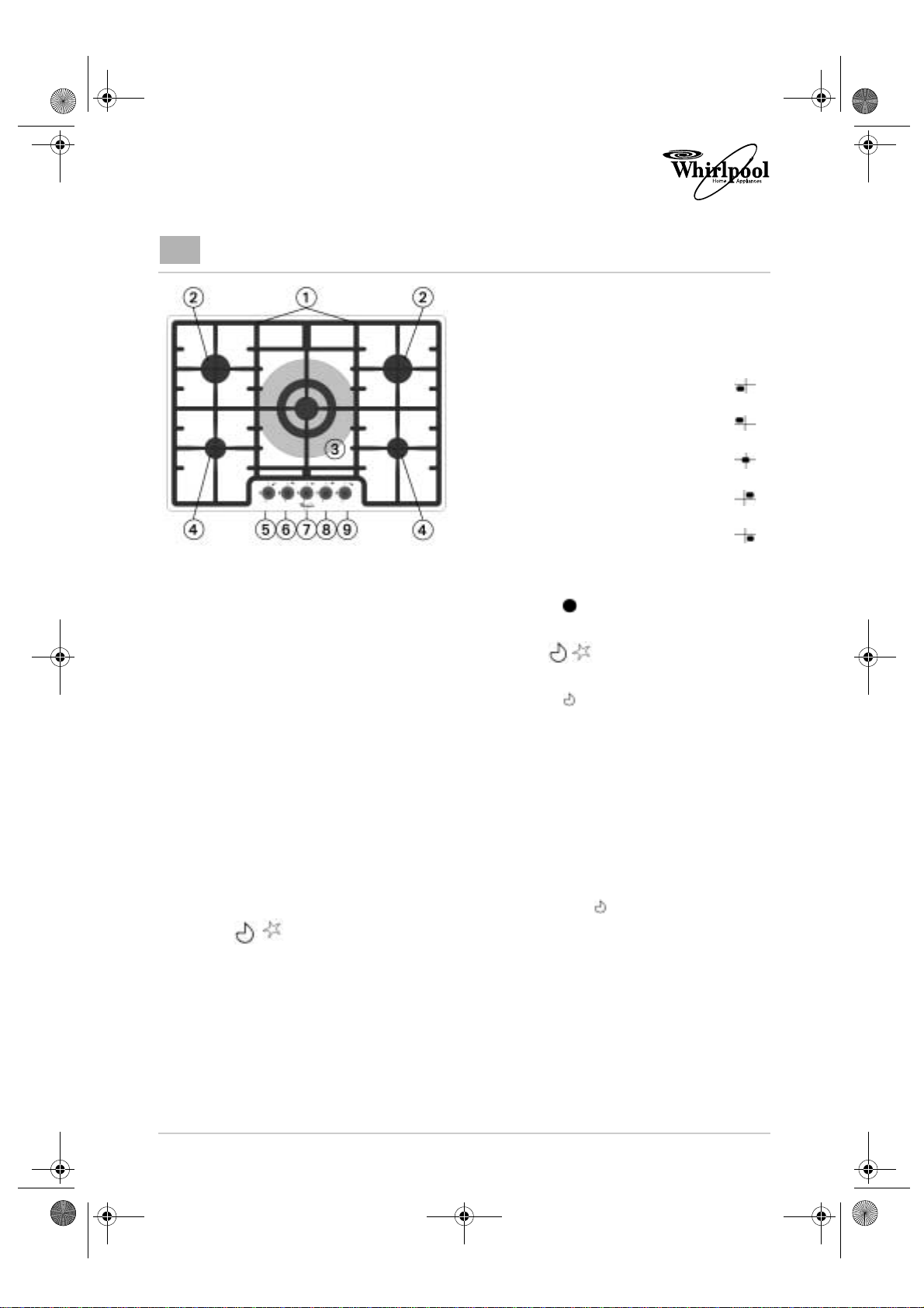
AKM 485 PRODUCT DESCRIPTION SHEET
IT
1. Removable grids
2. Medium burners
3. Triple crown burner
4. Auxiliary burner
5. Front left auxiliary burner
control knob
6. Rear left semi-rapid burner
control knob
7. Triple crown burner control
knob
8. Rear right semi-rapid burner
control knob
9. Front right auxiliary burner
control knob
Operation of burners with safety
device and electric ignition
To light one of the burners:
• Press the relative knob and turn it anticlockwise to the large flame and star
setting .
• At the same time, hold the knob down until
the burner ignites.
• After the burner has ignited, keep the knob
pressed for about 10 seconds.
• Release the knob.
If the burner does not ignite, repeat the operation.
Symbols
Shaded
circle
Large
flame
and star
Small
flame
Note:
— Should particular local conditions of the
delivered gas make the ignition of the burner
difficult, it is advisable to repeat the
operation with the knob turned to the small
flame setting .
— The burner safety device shuts off the gas
supply to the burner if the flame goes out
accidentally (because of a sudden draught,
an interruption in the gas delivery, boiling
over of liquids, etc.).
Tap closed
Maximum opening/delivery
and electric ignition
Minimum opening or
reduced delivery
5019 319 66063
Whirlpool is a registered trademark of Whirlpool USA

31966063GB.fm Page 2 Monday, March 21, 2005 9:28 AM
DIMENSIONS OF COOKING HOB AND WORKTOP (mm)
Fig.2
Adhesive sponge gasket
Fig.1
Fig.3
NOTE:
Important:
Important
Recommended for
laminated worktops with a
depth of less than 3mm
In the event a hood is fitted above the cooktop, please refer to the hood instructions
for the correct distance.
The following operation requires building and/or carpentry work so must be carried out
by a competent tradesman. Installation can be carried out on various materials such as
masonry, metal, solid wood or plastic laminated wood, as long as they are heatresistant (T 90°C).
: Manufacturer supervision is necessary for any other types of installation!
Attachment to support structure, flush-mounting model
Create an opening with the dimensions shown in figure 2 in the work surface, observing a minimum
distance of 50 mm from the rear edge (fig. 1). The lower part of the protective cover must be fully
accessible when the appliance is installed.
This appliance can be installed next to walls that are higher than the work surface, as long as the distance
“X” shown in the figure, to avoid any damage from overheating. Make sure there is a minimum of 750 mm
(Fig. 1) between the gas rings and any shelf that may be installed directly above them.
This type of appliance requires the worktop, the dimensions of which are shown shown in figure 2, to be
milled to a depth of 3 mm.
Note: for laminated worktops with a depth of less than 3 mm, mill the worktop as shown in figure 3.
Before inserting the cooktop, position the adhesive gasket “E” supplied around the milled surface (fig. 4).
 Loading...