

Page 1
3gb66054a.fm Page 1 Tuesday, April 12, 2005 12:20 PM
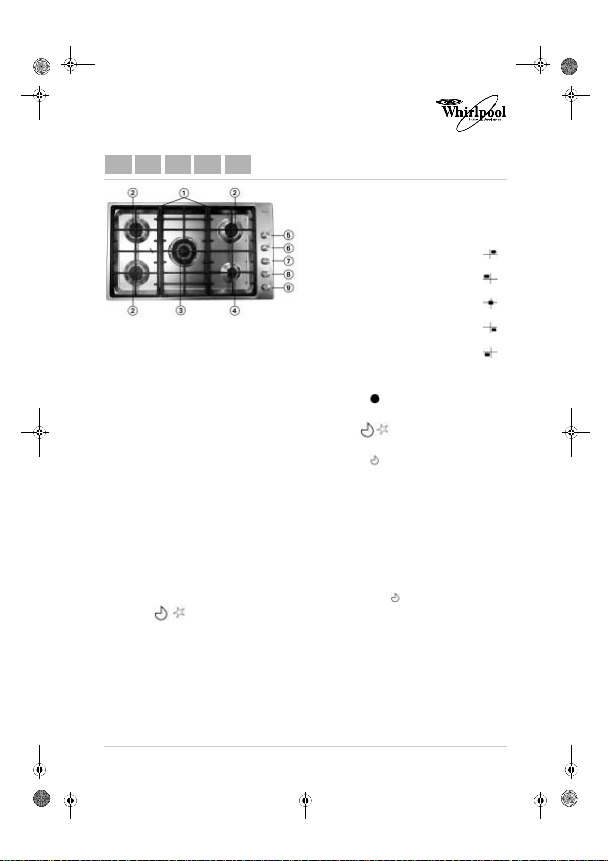
AKM 480 PRODUCT DESCRIPTION SHEET
IT CZ SK RU RO
1. Removable grids
2. Semi-rapid burners
3. Triple crown burner
4. Auxiliary burner
5. Right rear semi-rapid
burner control knob
6. Left rear semi-rapid
burner control knob
7. Triple crown burner
control knob
8. Front auxiliary burner
control knob
9. Front semi-rapid burner
control knob
Operation of burners with safety
device and electric ignition
To light one of the burners:
• Press the relative knob and turn it anticlockwise to the large flame and star
setting .
• At the same time, hold the knob down until
the burner ignites.
• After the burner has ignited, keep the knob
pressed for about 10 seconds.
• Release the knob.
If the burner does not ignite, repeat the operation.
Symbols
Shaded
circle
Large
flame
and star
Small
flame
Note:
— Should particular local conditions of the
delivered gas make the ignition of the burner
difficult, it is advisable to repeat the
operation with the knob turned to the small
flame setting .
— The burner safety device shuts off the gas
supply to the burner if the flame goes out
accidentally (because of a sudden draught,
an interruption in the gas delivery, boiling
over of liquids, etc.).
Tap closed
Maximum opening/delivery
and electric ignition
Minimum opening or
reduced delivery
5019 319 66054/A
Whirlpool is a registered trademark of Whirlpool USA
Page 2
3gb66054a.fm Page 2 Tuesday, April 12, 2005 12:20 PM
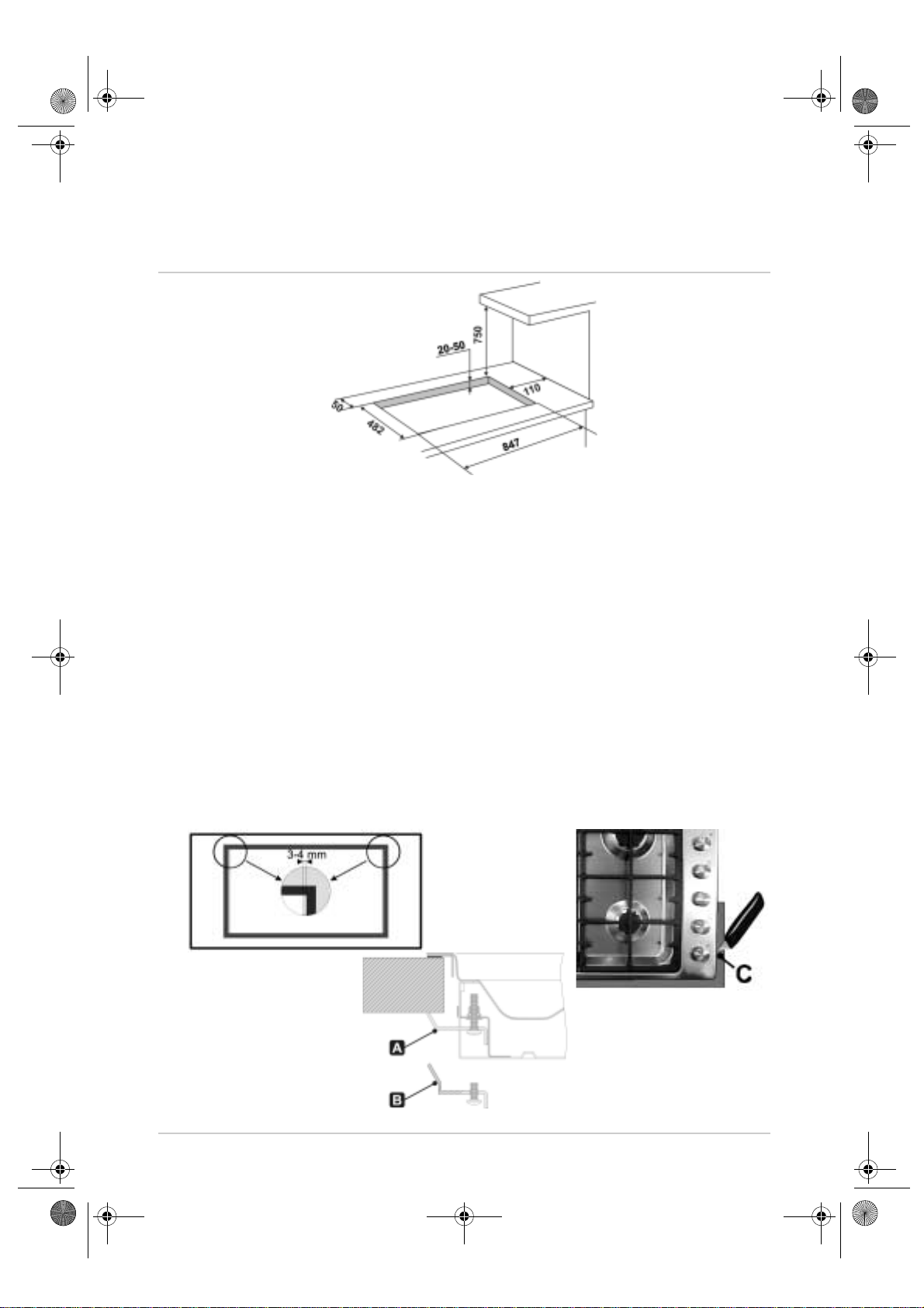
DIMENSIONS OF COOKING HOB AND WORKTOP (mm)
Fig.1
Note: In case of installation of a hood above the cooking hob, please refer to the hood
instructions for the correct distance.
Important:
Installation of this product requires masonry and/or carpentry work. Therefore, it must
be carried out by a competent technician. The appliance may be installed on various
surfaces, such as brickwork, metal, solid wood and plastic laminated wood, provided
they are heat resistant materials (T 90°C).
Installation of traditional built-in model
Provide an opening in the worktop in accordance with the dimensions shown in the figure, leaving a
minimum clearance of 50 mm from the rear edge.
The appliance can be positioned against walls which are higher than the worktop, leaving a distance of
110 mm, as shown in figure 1, in order to avoid damages caused by excessive heat. Make sure there is a
minimum vertical clearance of 750 mm between the burner flames and an overhead shelf.
Apply the seal supplied along the outer perimeter of the cutout as shown in the figures below, ensuring it
adheres to the full length of the perimeter. Depending on the model of hob to be installed, refer to the
dimensions shown in the figure. Please remember that the front and rear sides must only touch the edge of
the cutout.
To fit the hob, use brackets A or B supplied with it (depending on the depth of the worktop). Trim excess
seal off edge C.
The dimensions shown in the figure below refer from the cutout to the inner side of the seal.
Page 3

3gb66054a.fm Page 3 Tuesday, April 12, 2005 12:20 PM
INJECTORS TABLE CATEGORY II2H3+
Type of gas used
NATURAL GAS
(Methane) G20
LIQUID PETROLEUM
GAS
(Butane) G30
LIQUID PETROLEUM
GAS
(Propane) G31
Type of gas used
Type of
burner
Triple crown
semi-rapid
auxiliary
Triple crown
semi-rapid
auxiliary
Triple crown
semi-rapid
auxiliary
Appliance
model
Injector
marking
100/mm
133
97
72
94
65
50
94
65
50
Rated heat
capacity
kW
3.50
1.75
1.05
3.50
1.75
1.05
3.50
1.75
1.05
Total rated heat
capacity
kW
Rated
consumption
333 l/h
167 l/h
100 l/h
254 g/h
127 g/h
76 g/h
250 g/h
125 g/h
75 g/h
Total rated
consumption
Reduced
heat
capacity
kW
1.50
0.45
0.35
1.60
0.45
0.35
1.60
0.45
0.35
Gas pressure mbar
min. rat. max.
17 20 25
20 28-30 35
25 37 45
Air required
for burning
3
m
G20 20 mbar 5 gas 9.80 933 l/h 19.6
G30 28-30 mbar 5 gas 9.80 712 g/h 19.6
G31 37 mbar 5 gas 9.80 701 g/h 19.6
/h
Page 4

3gb66054a.fm Page 4 Tuesday, April 12, 2005 12:20 PM
 Loading...