

Whirlpool ADVANTECHCAE2792K, ADVANTECHCAE2762K, ADVANTECH CGE2761K, ADVANTECH CEE2790K, ADVANTECH CGE2791K Installation, Operation And Service Instructions
...Page 1
CONSUMER SERVICES TECHNICAL
EDUCATION GROUP PRESENTS
ADVANTECH
COMMERCIAL LAUNDRY PRODUCTS
Washers
CL-7
Metercase Equipped Models: # CAE2761K & CAE2762K
Full Console Card Ready Model: # CAE2792K
Freestanding Dryers
Metercase Equipped Models: # CEE2760K & CGE2761K
Full Console Card Ready Models: #CEE2790K & CGE2791K
Stack Dryers
Models: # CSP2770K & CSP2771K
JOB AID
Part No. 8178077
Page 2

FORWARD
This Whirlpool Job Aid, “ADVANTECH Commercial Laundry Products,” (Part No. 8178077),
provides the technician with information on the installation, operation, and service of ADVANTECH
Commercial Laundry Products. It is to be used as a training Job Aid and Service Manual. For
specific information on the model being serviced, refer to the “Literature Pack” provided with
ADVANTECH Commercial Laundry Products.
The Wiring Diagrams and Strip Circuits used in this Job Aid are typical and should be used for
training purposes only. Always use the Wiring Diagram supplied with the product when servicing
the unit.
GOALS AND OBJECTIVES
The goal of this Job Aid is to provide detailed information that will enable the service technician to
properly diagnose malfunctions and repair Whirlpool ADVANTECH
Products.
The objectives of this Job Aid are to:
• Understand and follow proper safety precautions.
• Successfully troubleshoot and diagnose malfunctions.
• Successfully perform necessary repairs.
• Successfully return the product to its proper operational status.
Commercial Laundry
WHIRLPOOL CORPORATION assumes no responsibility for any repairs made
on our products by anyone other than Authorized Service Technicians.
Copyright © July, 2004, Whirlpool Corporation, Benton Harbor, MI 49022
- ii -
Page 3

TABLE OF CONTENTS
Page
GENERAL............................................................................................................................................. 1-1
Safety First ...................................................................................................................................... 1-1
Model & Serial Number Designations ............................................................................................. 1-2
Model & Serial Number Label And Literature Pack Locations........................................................ 1-3
Specifications .................................................................................................................................. 1-4
Washers ....................................................................................................................................... 1-4
Freestanding Dryers .................................................................................................................... 1-5
Stack Dryers................................................................................................................................. 1-6
ADVANTECH
ADVANTECH
Literature Cross-Reference Chart ................................................................................................... 1-9
INSTALLATION INFORMATION ......................................................................................................... 2-1
Washers .......................................................................................................................................... 2-1
Dryers .............................................................................................................................................. 2-8
Money Acceptor Installation .......................................................................................................... 2-25
Money Acceptor Cross Reference.......................................................................... 1-7
Money Acceptor Manufacturer Contact Info / Warranty Info..................................... 1-8
PRODUCT OPERATION ...................................................................................................................... 3-1
ADVANTECH
ADVANTECH
System Overview ................................................................................................... 3-1
PC System & Palm Requirements ....................................................................... 3-2
COMPONENT ACCESS ....................................................................................................................... 4-1
WASHERS ............................................................................................................................................ 4-1
Washer Component Locations........................................................................................................ 4-1
Removing The Console Components ............................................................................................. 4-2
Removing The Money Acceptors & Metercase .............................................................................. 4-6
Removing The Hidden Lid Switch ................................................................................................. 4-10
Removing The Pump, Motor Start Capacitor, & Motor ................................................................. 4-11
Removing The Agitator & Transmission ....................................................................................... 4-13
Removing The Cabinet Assembly................................................................................................. 4-16
Removing The Tub Ring, Basket, Outer Tub, And Basket Drive Assembly ................................. 4-18
Removing The Suspension System & Base Assembly ................................................................ 4-21
Removing The Vacuum Break ...................................................................................................... 4-22
Removing The Dual Water Valve, Water Level Switch, And Drain Hose Assembly .................... 4-23
DRYERS ............................................................................................................................................. 4-25
Gas Dryer Component Locations.................................................................................................. 4-25
Electric Dryer Component Locations ............................................................................................ 4-25
Freestanding Dryers ........................................................................................................................... 4-26
Removing The Console Components ........................................................................................... 4-26
Removing The Money Acceptors & Metercase ............................................................................ 4-29
Removing The Cabinet ................................................................................................................. 4-33
Stack Dryers ....................................................................................................................................... 4-35
Removing The Console Components ........................................................................................... 4-35
Removing The Money Acceptors .................................................................................................. 4-38
Removing The ADVANTECH
Control Boards............................................................................. 4-40
Removing The Upper Dryer .......................................................................................................... 4-41
Removing The Collar Assembly.................................................................................................... 4-43
Freestanding And Stack Dryers .......................................................................................................... 4-44
Removing The Door Switch .......................................................................................................... 4-44
Removing The Thermal Fuse, Operating Thermostst, Drive Motor, & Broken Belt Switch .......... 4-45
Removing The Heater, The High-Limit Thermostat, & Thermal Cutoff......................................... 4-49
Removing The Burner Assembly, Flame Sensor, And High-Limit Thermostat............................. 4-50
Removing The Belt, Drum, & Rollers ............................................................................................ 4-53
Removing The Outlet Grille........................................................................................................... 4-55
Removing A Spark Quencher ....................................................................................................... 4-56
- iii -
Page 4

COMPONENT TESTING ...................................................................................................................... 5-1
Diagnostic Guide ............................................................................................................................. 5-1
WASHERS ............................................................................................................................................ 5-2
Motor ............................................................................................................................................... 5-2
Motor Thermal Protector ................................................................................................................. 5-3
Motor Start Capacitor ...................................................................................................................... 5-3
Hidden Lid Switch ........................................................................................................................... 5-4
Dual Water Valve ............................................................................................................................ 5-4
Water Level Switch ......................................................................................................................... 5-5
Basket Drive Shaft Checks ............................................................................................................. 5-6
GAS & ELECTRIC DRYERS ................................................................................................................ 5-7
Gas Burner Coils ............................................................................................................................. 5-7
Burner Ignitor .................................................................................................................................. 5-7
Flame Sensor .................................................................................................................................. 5-8
High-Limit Thermostat ..................................................................................................................... 5-8
Heater (Electric Models Only) ......................................................................................................... 5-9
Drive Motor.................................................................................................................................... 5-10
Thermal Fuse ................................................................................................................................ 5-11
Operating Thermostat ................................................................................................................... 5-12
Thermal Cutoff .............................................................................................................................. 5-13
Door Switch ................................................................................................................................... 5-14
DIAGNOSIS & TROUBLESHOOTING ................................................................................................ 6-1
Diagnosis ........................................................................................................................................ 6-1
Washers With Metercase ............................................................................................................. 6-1
Freestanding Dryers Without Metercase ..................................................................................... 6-8
Stack Dryers............................................................................................................................... 6-13
WIRING DIAGRAMS & STRIP CIRCUITS ........................................................................................... 7-1
Wiring Diagrams.............................................................................................................................. 7-1
Washers ....................................................................................................................................... 7-1
Freestanding Electric Dryers........................................................................................................ 7-2
Freestanding Gas Dryers ............................................................................................................. 7-3
Stack Electric Dryers.................................................................................................................... 7-4
Stack Gas Dryers ......................................................................................................................... 7-5
Dryer Strip Circuits .......................................................................................................................... 7-6
CONTROL BOARD DIAGNOSTICS..................................................................................................... 8-1
ADVANTECH WASHER PARTS...........................................................................................................9-1
SERVICE POINTERS....................................................................................................... Back Of Manual
WHIRLPOOL COMMERCIAL LAUNDRY CONTACT INFO........................................Inside Back Cover
- iv -
Page 5
GENERAL
SAFETY FIRST
Your safety and the safety of others is very important.
We have provided many important safety messages in this Job Aid and on the appliance. Always
read and obey all safety messages.
This is the safety alert symbol.
This symbol alerts you to hazards that can kill or hurt you and others.
All safety messages will follow the safety alert symbol and either the word
“DANGER” or “WARNING.” These words mean:
You can be killed or seriously injured if you don’t
DANGER
WARNING
All safety messages will tell you what the potential hazard is, tell you how to reduce the chance
of injury, and tell you what can happen if the instructions are not followed.
immediately follow instructions.
You can be killed or seriously injured if you don’t
follow instructions.
1-1
Page 6

MODEL & SERIAL NUMBER DESIGNATIONS
Cabi
Width in Inch
(29″
27″
MODEL NUMBER
MODEL NUMBER C A E 2 7 6 1 K Q 0
PRODUCT GROUP
C = Commercial Laundry
PRODUCT IDENTIFICATION
A= Automatic Washer
E = Electric Dryer
G = Gas Dryer
S = Stack Dryer
CONTROL CODE
E = Electronic Control
M = Electromechanical
P = Pushbutton Single Unit or Stacked Pair
W = Resource Saver
FEATURE CODE
net
FEATURE / VARIATIONS
4 = Metercase or Coinslide Equipped Stack W/O Windows
5 = Metercase and Coinslide Equipped
6 = Metercase or Coinslide Equipped Stack With Windows
7 = Card Reader Ready / Equipped Stacked Pair
9 = Full Width Console
FEATURE CODE
0 = Electric
1 = Single Speed or Gas
2 = Two Speed
es
or
)
YEAR OF INTRODUCTION
J = 2000, K = 2001, L = 2002, M = 2003, P = 2004, R = 2005, S = 2006
COLOR CODE
Q = White
ENGINEERING REVISION NUMBER
0 = Basic, 1 = 1st Revision, 2 = 2nd Revision
SERIAL NUMBER
SERIAL NUMBER C L 16 02287
MANUFACTURING SITE
C = Clyde, OH (Washers)
M = Marion, OH (Dryers)
YEAR OF PRODUCTION
L = 2001, M = 2002, N or P = 2003,
R = 2004, S = 2005, T = 2006
WEEK OF PRODUCTION
PRODUCT SEQUENCE NUMBER
1-2
Page 7
MODEL & SERIAL NUMBER LABEL
AND LITERATURE PACK LOCATIONS
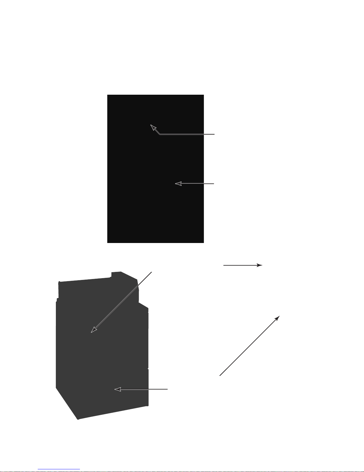
The Model & Serial Number label and Literature Pack locations are shown below. The Literature
Pack includes a wiring diagram, parts list, and tech sheet.
WASHERS
Model & Serial Number
Label (located on the
washer top rear center
under the lid)
Literature Pack
(located behind the
front access panel)
FREESTANDING DRYERS
STACK DRYERS
Model & Serial Number
Label (located inside the
door jamb on the left side)
Literature Pack
(located behind the
front access panel)
1-3
Page 8

1- 4
Page 9

1- 5
Page 10

1- 6
Page 11

1- 7
Page 12

1- 8
Page 13
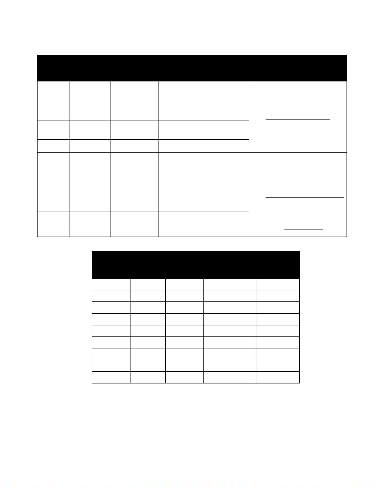
LITERATURE CROSS-REFERENCE CHART
Archway
Lit
Number
N /A Model specific
N / A 8524745
N / A 8178077
CWLL086 8524743
CWLX043 8524744 Software Install CD Management Software CD only
CWLL082b N / A Sales Literature
Whirlpool
Part
Number
Description Contains
Parts breakdown, Wiring Diagram,
Product
Literature Pack
PC User’s
Assembly
Service Manual/
Job Aid
PC User’s Guide
(Software Manual)
Tech Sheet, and Installation
Instructions. Packed with all
Whirlpool ADVANTECH
Complete Palm handheld application,
PC Management Software CD and
Software Manual
Complete Diagnostic & Technical
Reference manual
Complete Palm handheld application,
PC Management Software Manual
Product Specifications, Installation
Instructions, & Energy Usage
products
Ordering & Viewing Information
Available through Whirlpool Corporation
Literature Department 1-800-851-4605
also available online:
www.cltpsc.whirlpoolcorp.com
products and more,
Commercial Laundry link
-
Available at
Also available through Whirlpool
Corporation Literature Department
and for selected Trade Partners at
products and more, Commercial
Available at
www.coinop.com, or call
1-800-643-3444.
www.cltpsc.whirlpoolcorp.com,
Laundry link, or call
1-800-851-4605
www.coinop.com, or call
1-800-643-3444
Model
Number
Wiring
Diagram
Service
Parts List
Tech Sheet
(Technical Data)
Installation
Instructions
CAE2761K 8524730B 8524726 8524734 8524739
CAE2762K 8524731B 8524727 8524734 8524739
CAE2792K 8524731B 8524729 8524738 8524742
CGE2761K 8527854D 8527804 8527808 8527809
CEE2790K 8527859C 8527805 8527811 8527810
CEE2760K 8527854D 8527803 8527808 8527809
CGE2791K 8527859C 8527806 8527811 8527810
CSP2770K 8527882A* 8527819 8527886 8527892
CSP2771K 8527882A* 8527819 8527886 8527892
* CSP Stack Dryers have a wiring diagram label (#8527883A) on the upper dryer toe panel in addition to the diagram
in the Literature Pack.
1-9
Page 14

— NOTES —
1-10
Page 15

WASHER
2-1
Page 16
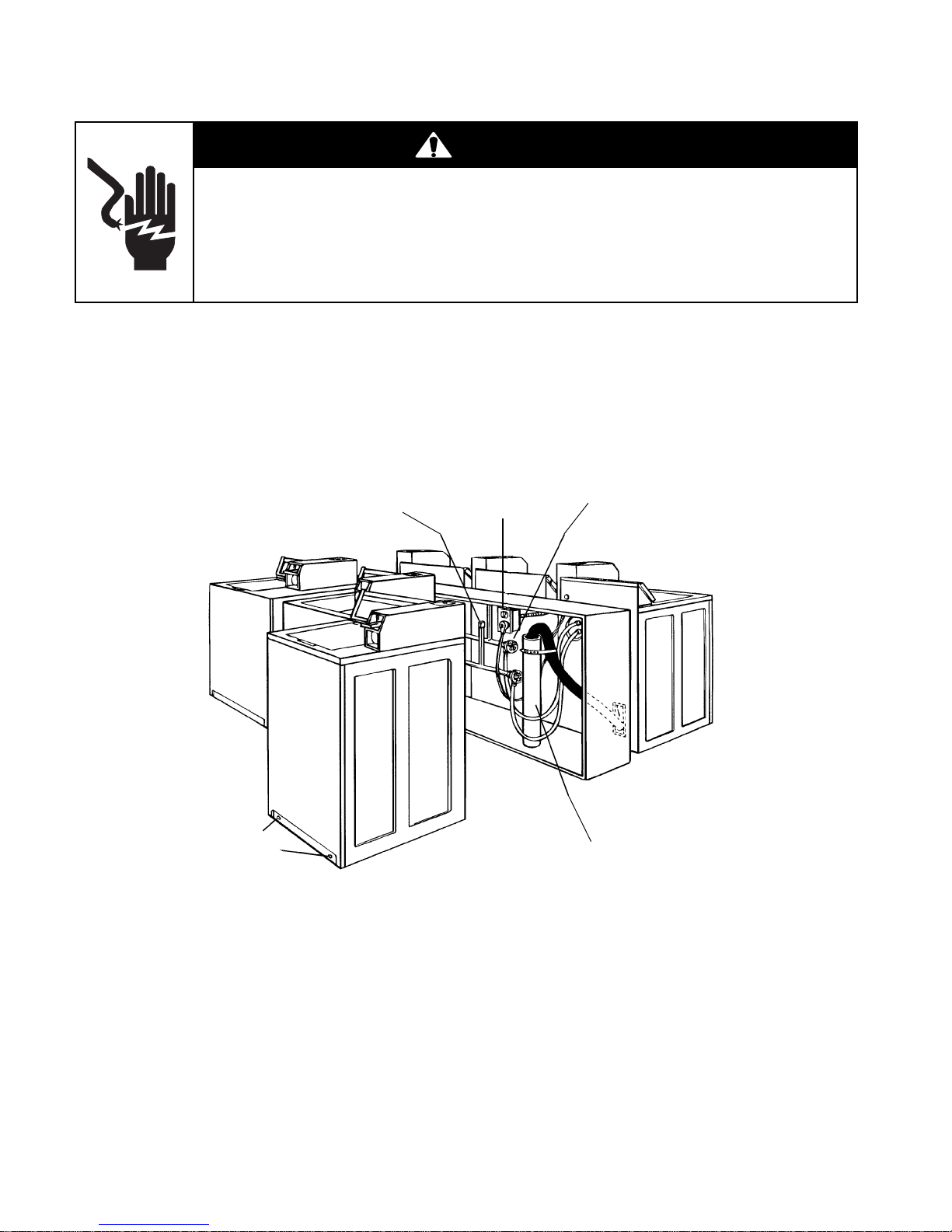
Washer Installation Instructions
Disconnect power before servicing.
Replace all parts and panels before operating.
Failure to do so can result in death or electrical shock.
BEFORE YOU START
WARNING
Electrical Shock Hazard
Check location where
washer will be installed.
Proper installation is your
responsibility. Make sure
you have everything necessary for correct installation.
Untape and
open washer
lid. Remove
packages and
hoses from
washer.
#T-20 Torx
Screws
On coin-operated washers,
front access to the pump area
is available by removing the
two #T-20 Torx screws and
then removing the front panel.
Important: Observe all
governing codes and
ordinances.
Single washer installations require 30 cm
(12 inch) minimum
risers to provide an
air cushion and
prevent noise and
damage to valves.
A floor drain should be provided
under the bulkhead. Prefabricated
bulkheads with electrical outlets,
water supply lines, and drain facilities should be used only where local
codes permit.
Grounded electrical
outlet is required.
See “Washer Electrical
Requirements” on
page 2-3.
Level Floor:
Maximum slope
under washer is
2.5 cm (1 inch).
Hot and cold water faucets must be
within 1.2 meters (4 feet) of the back of
the washer and provide water pressure
690 kPa (10-100 PSI). A pressure reduction valve should be used in the supply
line where inlet pressure entering the
building exceeds 690 kPa (100 PSI) to
prevent damage to the washer mixing
valve.
NOTE: Water Heater—Set to
deliver 60°C to 70°C (140°F to
160°F) water to the washer.
Standpipe drain system: Needs a
5 cm (2 inch) minimum carry-away
capacity of 64.4 liters (17 gallons)
per minute. Top of standpipe must
be at least 86.4 cm (34 inches) high
and no higher than 183 cm (72 inches)
from bottom of washer.
Support: Floor must be sturdy enough
to support loaded washer weight of 143
Kg (315 pounds).
2-2
Page 17
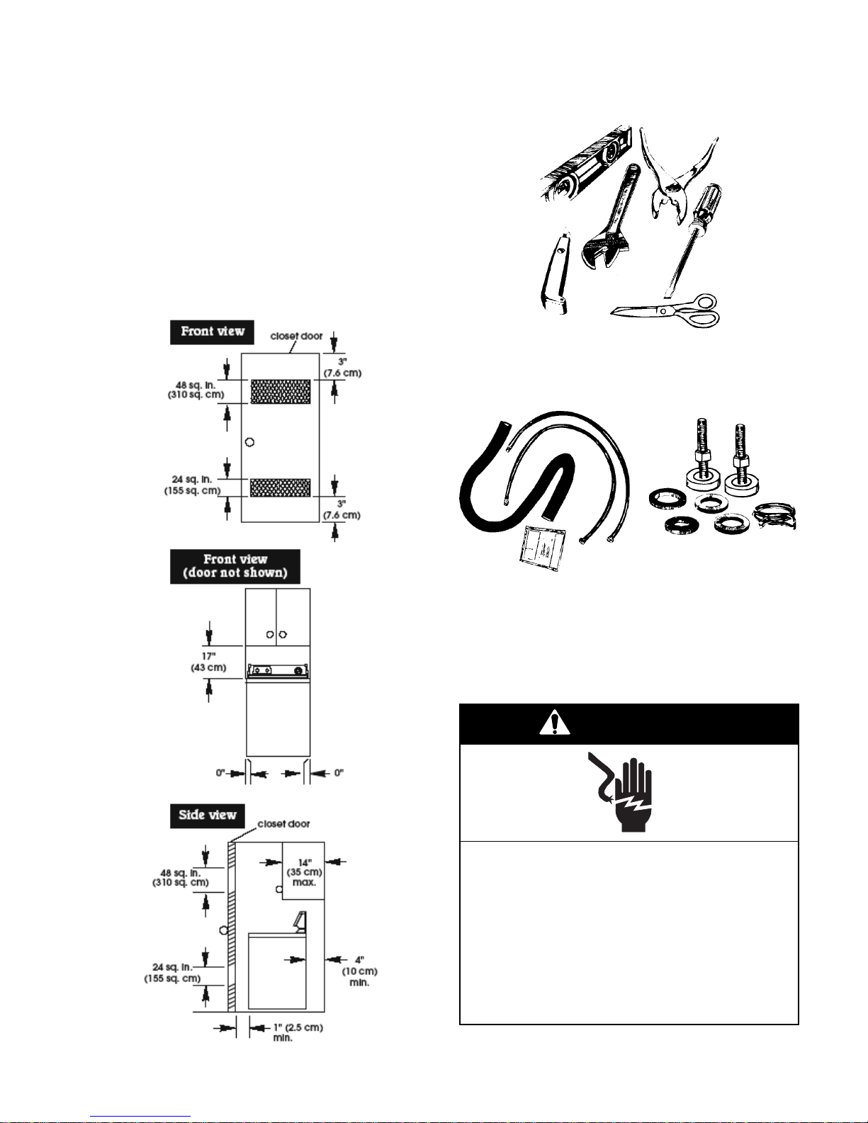
RECESSED AREA INSTRUCTIONS
This washer may be installed in a recessed
area or a closet. The installation dimensions
shown are the minimum spaces allowable.
Additional spacing should be considered for
ease of installation and servicing. If the closet
door is installed, the minimum air openings at
the top and bottom of the door are required.
Louvered doors with air openings in the top and
bottom are acceptable. Companion appliance
spacing should be considered.
TOOLS NEEDED FOR
INSTALLATION
Level Pliers
Wrench
Utility
Knife
Scissors
PARTS SUPPLIED FOR
INSTALLATION
Flat-Blade
Screwdriver
1 Hose Clamp
2 Inlet Hoses
4 Flat Washers
2 Front Leveling Legs W/Nuts
1 Drain Hose
WASHER ELECTRICAL
REQUIREMENTS
WARNING
Electrical Shock Hazard
Plug into a grounded 3-prong outlet.
Do not remove ground prong.
Do not use adapter.
Do not use an extension cord.
Failure to follow these instructions can
result in death, fire, or electrical shock.
2-3
Page 18

If codes permit and a separate ground wire is
used, it is recommended that a qualified electrician determine that the ground path is adequate.
Do Not ground to a gas pipe.
Check with a qualified electrician if you are not
sure the washer is properly grounded.
Do Not have a fuse in the neutral or ground
circuit.
INSTALLING THE WASHER
WARNING
Excessive Weight Hazard
Use two or more people to move and
install washer.
Failure to do so can result in back or
other injury.
A 120-volt, 60-Hz, AC-only, 15- or 20-ampere
fused electrical supply is required. (Timedelay fuse or circuit breaker is recommended.) It is recommended that a separate
circuit serving only this appliance be provided.
Grounding Instructions
For the safety of the customer, this washer
must be grounded. The washer is equipped
with a power supply cord that has a 3-prong
grounding plug.
3-Prong Grounding Type Outlet
3-Prong
Grounding
Plug
Ground
Power Supply
Cord
Prong
To minimize a possible shock hazard, the cord
must be plugged into a mating 3-prong grounding-type receptacle, which has been grounded
in accordance with National Electrical Code
(ANSI/NFPA 70), and all local and state codes.
If a mating outlet is not available, it is the
personal responsibility and obligation of the
customer to have a properly grounded 3-prong
outlet installed by a qualified electrician.
Removing the shipping strap is necessary for
smooth operation. If the shipping strap is not
removed, the washer will make excessive noise.
1. Do not cut yellow strap. Pull yellow strap
firmly, until completely removed from
washer. There will be two cotter pins on the
end of the shipping strap when it is pulled
out of the washer. The electrical plug is
attached to this shipping strap.
2. The shipping strap plug must be completely
removed from the washer for the self-leveling legs to be released. Save the shipping
strap for use in step 7.
IMPORTANT: Improper connection of the
equipment-grounding conductor can result in a
risk of electric shock. Do not modify the plug
provided with the appliance. If it will not fit the
outlet, have a proper outlet installed by a qualified electrician.
2-4
Page 19
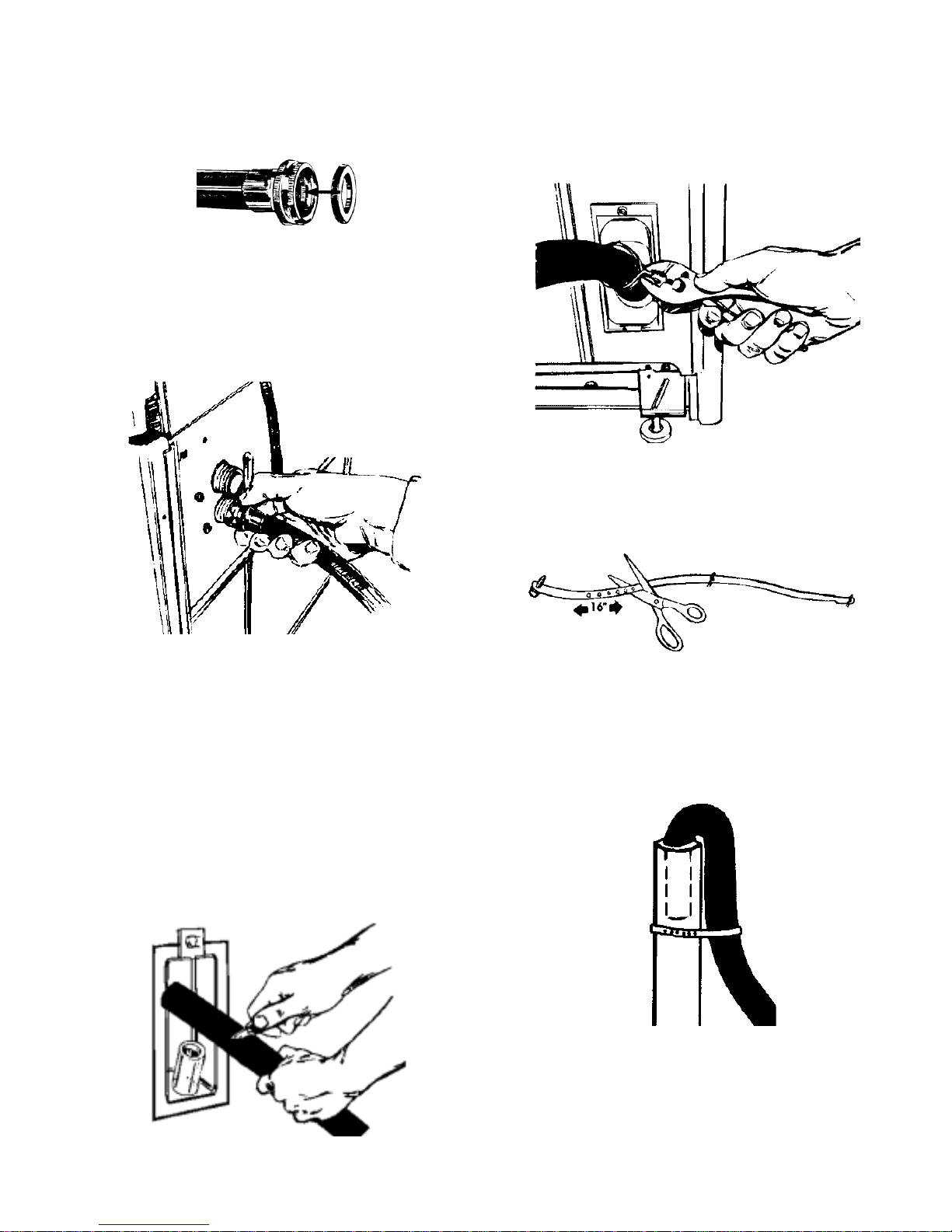
3. Insert a flat washer into each end of the inlet hoses. Check that washers are firmly
seated in couplings.
4. Attach hose to bottom inlet valve opening
first. Then second hose to top inlet. Tighten
couplings by hand; then use pliers to make
an additional two-thirds turn. Slide washer
onto cardboard or hardboard before moving across floor.
Inlets are plastic.
Do not strip or
crossthread.
6. Place hose clamp over washer drain connector. Push drain hose onto washer connector. Use pliers to open clamp and slide
clamp over drain hose. Check for good fit.
7. Measure and mark a point approximately
16″ (40.6 cm) from the plug end of
the shipping strap. Cut the shipping strap
at this point.
5. Move washer close to final position. Put
the “hooked” end of drain hose into the
standpipe. Estimate length of drain hose
needed when washer is in final position.
Hose must be cut exactly to length so the
“hooked” end is held tightly over edge of
standpipe. If drain hose is too long, cut
straight end of hose. (Do not cut the
“hooked” end of drain hose.) Do not
force excess length of drain hose down the
standpipe. This could cause siphoning. See
step 8.
40.6 cm
8. Put the “hooked” end of drain hose into the
standpipe. Tightly wrap the shipping strap
around the standpipe. Push plug into the
nearest hole in the shipping strap. Check
that hose is not twisted or kinked and is
securely in place.
2-5
Page 20
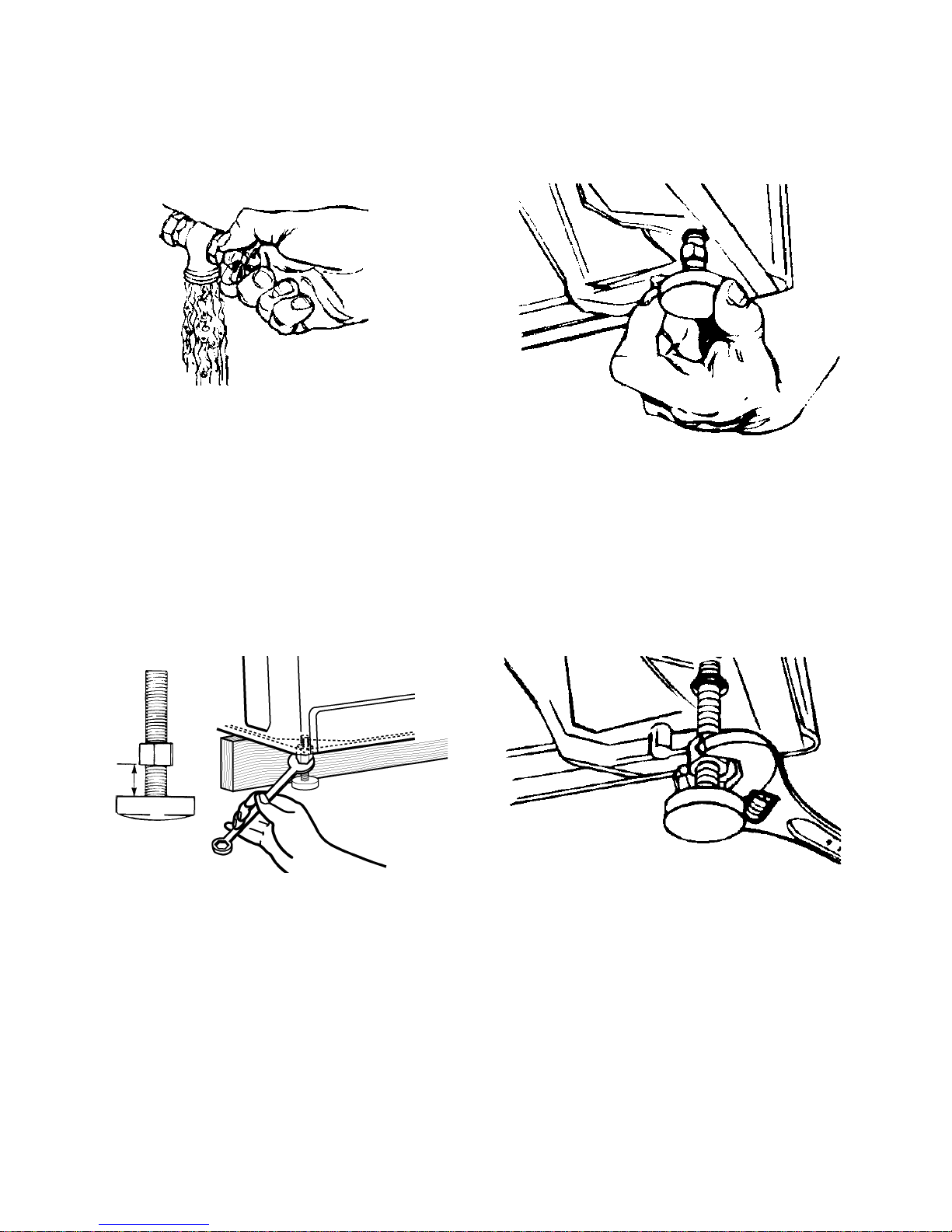
9. Before attaching water inlet hoses, run water
through both faucets into a bucket. This will
get rid of particles in water lines that might
clog hoses. Mark which is the hot water
faucet.
10.Attach bottom hose (inlet marked “H”) to
hot water faucet. Attach top (inlet marked
“C”) to cold water faucet. Tighten coupling
to faucet by hand, then use pliers to make
final two-thirds turn.
11.Prop up the front of the washer about 4″
(10.2 cm) with a wood block, or similar
object. The block needs to support the
weight of the washer.
12.Screw the locknut onto each foot to within
1″ (2.5 cm) of the base.
13.Screw the feet into the correct holes at the
front corner of the washer until the nuts
touch the washer. NOTE: Do not tighten the
nuts until the washer is level, step 17.
14.Tilt washer backward and remove the wood
block. Gently lower washer to floor. Move
washer to its permanent location. Remove
cardboard or hardboard from under washer.
15.Tilt washer forward raising back legs 1″
(2.5 cm) off of floor. To adjust rear leveling
legs, gently lower washer to floor.
2.5 cm
(1″)
2-6
Page 21
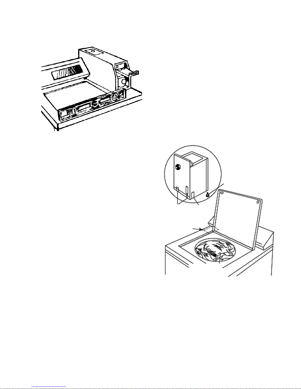
16.Check washer level by placing a level on
Hidden
Lid Switch
top of the washer, first side-to-side, then
front-to-back.
17.If washer is not level, adjust the front legs up
or down. Make final check with level. Best
results are obtained when the washer is
tilted 1/4 bubble toward the rear and level sideto-side. When washer is level, use wrench to turn
nuts on front legs up tightly against washer
base. If nuts are not tight against washer base,
the washer may vibrate.
MOVING THE WASHER
To move the washer to a new location, perform
the following steps:
1. Remove the front legs from the base of the
washer.
2. Place both rear leveling legs in the upper
position and tape them securely in place.
3. Apply tape to the side and bottom of the
cabinet near the rear.
4. Open the washer lid, wedge a blanket between the tub ring and the cabinet top to
keep the tub from moving.
5. Move the washer to the desired location. Be
careful not to drop the washer while using a
hand truck.
Wedge blanket
between tub ring
and cabinet top
Remove front legs
18.Check that all parts are now installed. If
there is an extra part, go back through steps
to see which step was skipped.
19.Turn on water faucets and check for leaks.
Tighten couplings if there is leaking. Do not
over tighten; this could cause damage to
faucets.
20.Check that you have all of your tools. Check
that the shipping strap with 2 cotter pins and
plug was removed from the back of the
washer and used to secure the drain hose.
If entire strap is not removed, washer may
vibrate and be noisy.
21.Untape power supply cord.
22.Plug into a grounded 3-prong outlet.
23.Install the chosen money acceptor per the
instructions under the appropriate money
acceptor section of this Job Aid.
Tape rear
legs in “up”
position
Tape 2
sides
NOTE: Do not
place blanket
in this area to
protect hidden
lid switch
2-7
Page 22

2-8
Page 23

Dryer Installation Instructions
GAS REQUIREMENTS
WARNING
Explosion Hazard
Use a new AGA- or CSA-approved gas
supply line.
Install a shutoff valve.
Securely tighten all gas connections.
If connected to L.P. have a qualified
person make sure gas pressure does
not exceed 13″ (33 cm) water column.
Examples of a qualified person include
licensed heating personnel, authorized
gas company personnel, and
authorized service personnel.
Failure to do so can result in death,
explosion, or fire.
Observe all governing codes and ordinances.
1. This installation must conform with local
codes, or in absence of local codes with the
National Fuel Gas Code ANSI Z223.1/NFPA
54 or the CAN/CGA - B149 installation codes.
2. The design of this dryer has been certified
by the CSA International for use at altitudes
up to 10,000 feet (3048 m) above sea level,
at the BTU rating indicated on the model/
serial plate.
Burner input adjustments are not required
when the dryer is operated up to this elevation. When installed above 10,000 feet (3048 m),
a four percent (4%) reduction of the burner
BTU rating shown on the model/serial plate
is required for each 1,000 foot (305 m) increase
in elevation.
For assistance when converting to other
gas types and/or installing above 10,000
feet (3048 m) elevation, contact your local
service company.
3. Check that dryer is equipped with the correct burner for the particular type of gas
used. Burner information can be found on
the serial/rating plate in the door well of the
appliance. If this information does not agree
with the type of gas available, see your
dealer.
4. This dryer is equipped for use with NATURAL GAS. It is certified by CSA International for manufactured, mixed and L.P.
(propane and butane) gases with appropriate conversion. No attempt shall be made
to convert the appliance from the gas specified on the serial/rating plate for use with a
different gas without consulting the serving
gas supplier. A qualified service technician
must do conversion. Gas conversion kit
part numbers are listed on the gas valve
burner base.
5. Provide a rigid gas supply line of 1/2″ IPS
pipe to the dryer location. If the total length
of the supply line is more than 20 feet (6.1 m),
larger pipe will be needed. For L.P. gas
usage, 3/8″ approved copper tubing may
be used. Pipejoint compounds suitable for
use with LP gas should be used.
2-9
Page 24
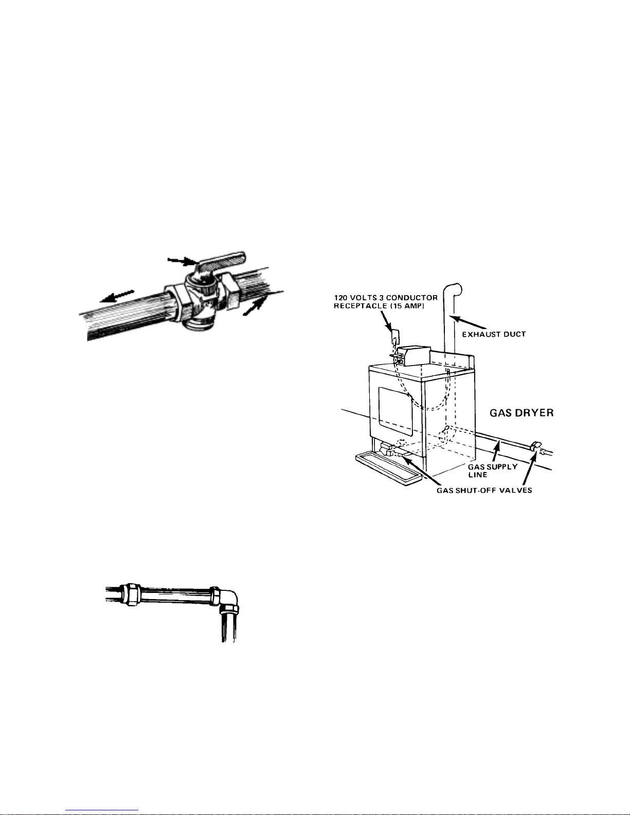
6. The supply line shall be equipped with a
shutoff valve installed within 6 feet (1.8 m)
of dryer in accordance with the American
National Standard National Fuel Gas Code,
ANSI Z223.1—latest edition*. In Canada,
an individual manual shutoff valve must be
installed in accordance with the B149 installation codes CAN/CGA B149.1 and
CAN/CGA B149.2**. This valve should be
located in the same room as the dryer and
should be in a location that allows ease of
opening and closing. Do not block access
to the shutoff valve.
shutoff valve
“open” position
to dryer
gas supply line
7. If the dryer is installed in a confined area
such as a bathroom or closet, provision
must be made for enough air for combustion and ventilation. Check governing codes
and ordinances.
11.For ease of installation, operation and servicing (if ever needed) adequate space
should be provided around the dryer.
12.A 1/8″ NPT plugged tapping, accessible for
gauge testing, must be installed immediately upstream of the gas supply connection to the dryer. The dryer must be disconnected from the gas supply piping system
during any pressure testing of the system at
test pressures in excess of 1/2 psig. The
dryer must be isolated from the gas supply
piping system by closing the equipment
shutoff valve during any pressure testing of
the gas supply piping system at test pressures equal to or less than 1/2 psi (3.45 kPa).
8. If local codes and ordinances permit, it is
recommended that new flexible metal tubing, design-certified by the AGA or CSA, be
used for connecting the dryer to the gas
supply line. (The gas feed pipe which extends through the lower rear of the dryer is
provided with 3/8″ metal pipe thread.)
9. If rigid pipe is used as a gas supply line, a
combination of pipefittings must be used to
obtain an in-line connection to the dryer.
rigid pipe
10.Make sure that the lower edges of the
cabinet, plus the back and bottom sides of
the dryer are free of obstructions to permit
adequate clearance of air openings for combustion air (see page 2-8 for minimum
spacing requirements).
Copies of the standards listed above may be
obtained from:
* American Gas Association
1515 Wilson Blvd.
Arlington, Virginia 22209
** CSA International
8501 East Pleasant Valley Road
Cleveland, Ohio 44131-5575
2-10
Page 25
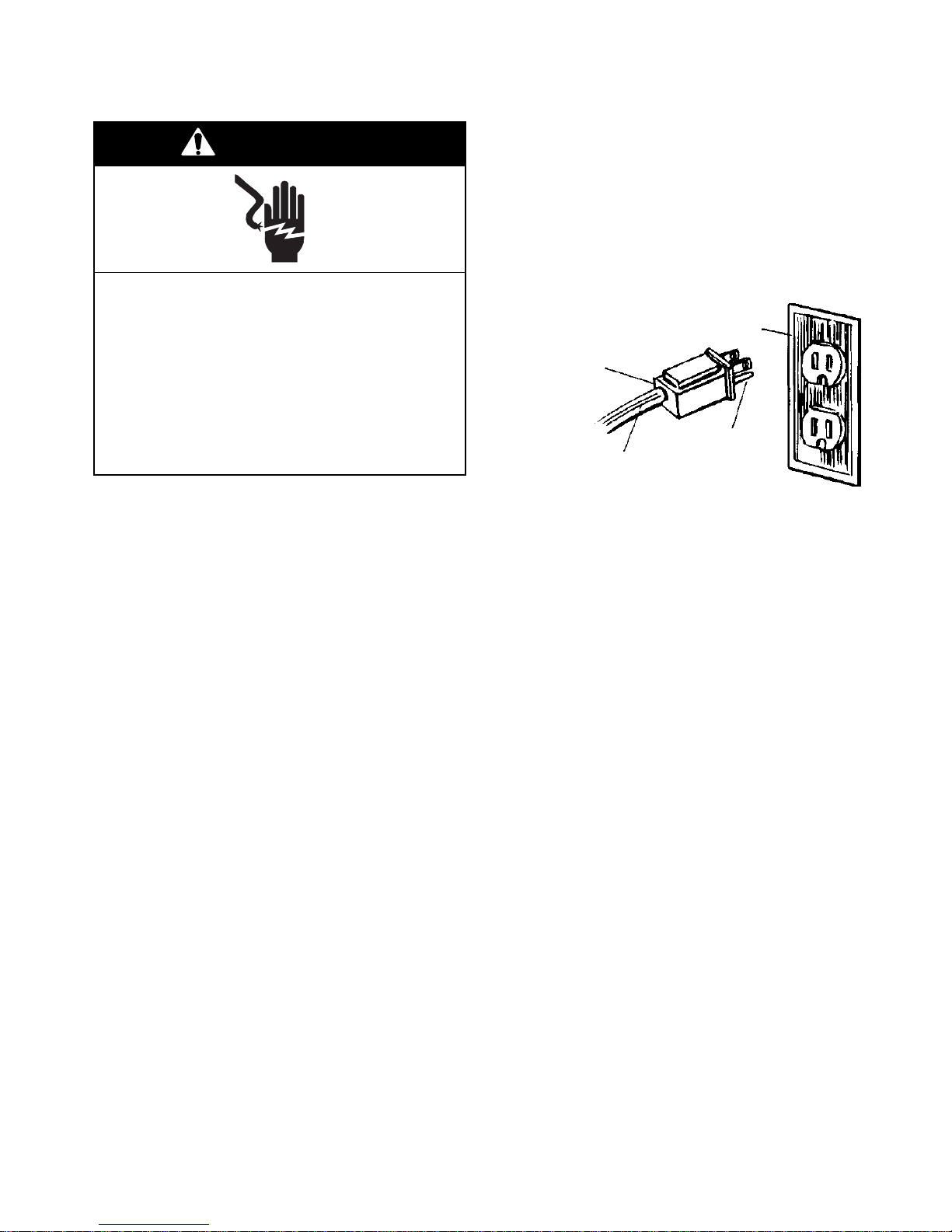
ELECTRICAL REQUIREMENTS
WARNING
Electrical Shock Hazard
Plug into a grounded 3-prong outlet.
Do not remove ground prong.
Do not use an adapter.
Do not use an extension cord.
Grounding Instructions
This appliance must be grounded. In the event
of malfunction or breakdown, grounding will
reduce the risk of electric shock by providing a
path of least resistance for electric current. The
power supply cord plug must be plugged into
an appropriate outlet that is properly installed
and grounded in accordance with all local
codes and ordinances.
3-Prong Grounding-
Type Outlet
3-Prong
Grounding
Plug
Failure to follow these instructions can
result in death, fire, or electrical shock.
Observe all governing codes and ordinances.
If codes permit and a separate ground wire is
used, it is recommended that a qualified electrician determine that the ground path is adequate.
A 120-volt, 60-Hz, AC-only, 15- or 20-ampere
fused electrical supply is required. A timedelay fuse or circuit breaker is recommended.
It is recommended that a separate circuit serving only this appliance be provided.
The dryer, when installed, must be electrically
grounded in accordance with local codes, or in
the absence of local codes, with the National
Electrical Code, ANSI/NFPA 70*, or the Canadian Electrical Code, CSA C22.1**
Copies of the standards listed above may be
obtained from:
Ground
Power Supply
Cord
Prong
IMPORTANT: Improper connection of the
equipment-grounding conductor can result in a
risk of electric shock. Check with a qualified
electrician or serviceman if you are in doubt as
to whether the appliance is properly grounded.
Do not modify the plug provided with the appliance. If it will not fit the outlet, have a proper
outlet installed by a qualified electrician.
* National Fire Protection Association
One Batterymarch Park
Quincey, Massachusetts 02269
** CSA International
8501 East Pleasant Valley Road
Cleveland, Ohio 44131-5575
2-11
Page 26
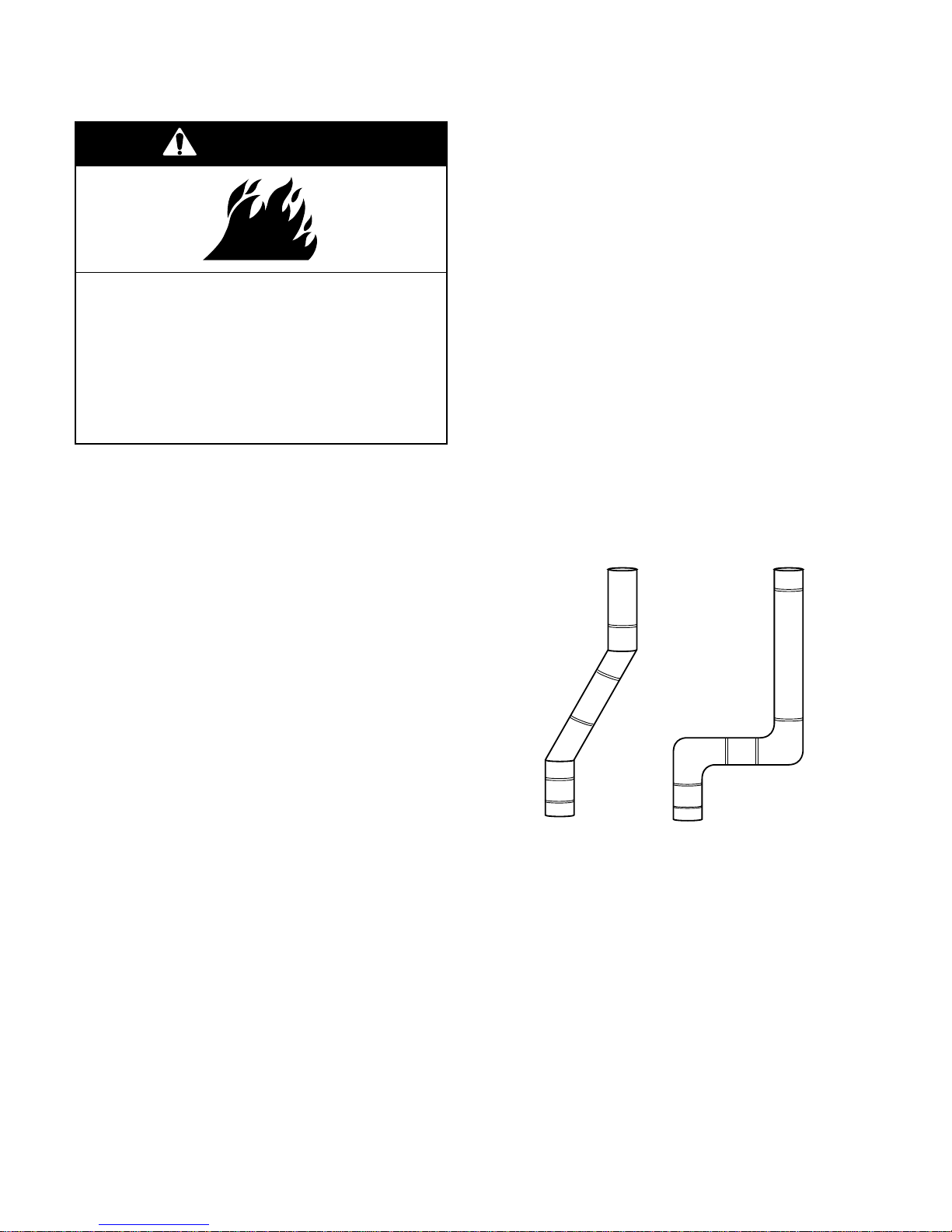
DRYER EXHAUST REQUIREMENTS
WARNING
6. 4″ (10.2 cm) metal exhaust vent is required.
Plan the installation to use the fewest number of elbows and turns. Use 4″ (10.2 cm)
vent clamps to secure the vent system.
7. A metal flexible vent must be fully extended
and supported when the dryer is in its final
position. DO NOT KINK OR CRUSH THE
VENT.
Fire Hazard
Use a heavy metal vent.
Do not use a plastic vent.
Do not use a metal foil vent.
Failure to do so can result in death or
fire.
1. Do not use a non-metal flexible vent, a
metal vent that is smaller than four inches in
diameter, or exhaust hoods with magnetic
latches.
2. The dryer must be exhausted outdoors.
3. Do not exhaust the dryer into a gas vent,
chimney, wall, ceiling, or the concealed
space of a building.
4. Do not install flexible vent in enclosed walls,
ceilings, or floors.
5. If using an existing exhaust system, clean
the lint from the entire length of exhaust
system. Make sure the exhaust hood is not
plugged with lint. The exhaust system should
be inspected and cleaned yearly. Replace
any plastic or metal foil exhaust vent with
rigid metal, or flexible metal vent.
8. A metal flexible vent must be completely
open to allow adequate exhaust air to flow.
9. Allow as much room as possible when
using elbows or making turns. Bend vent
gradually to avoid kinking. Remove any
excess flexible vent to avoid sagging and
kinking that may result in reduced airflow.
The exhaust outlet is located at the center
of the bottom dryer back. The exhaust vent
can be routed up, down, left, right, and
behind the dryer, or straight out the back.
exhaust airflow
better
exhaust
airflow
good
exhaust
airflow
2-12
Page 27
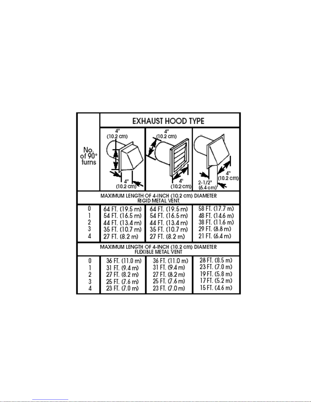
The maximum length of an exhaust system
depends upon the type of vent used, the number of elbows, and the type of exhaust hood.
The maximum lengths for both rigid and flexible venting is shown in the chart below.
For exhaust systems not covered by the exhaust length chart, see the Whirlpool Service
Manual: “Exhausting Whirlpool Dryers,” Part
No. 603197, which is available from your Whirl-
pool parts distributor. Also refer to Section 8.
If a dryer is installed in a confined area, it must
be exhausted to the outside, and provision
made for enough air for combustion and ventilation. Check governing codes and ordinances.
A 4″ (10.2 cm) outlet hood is preferred, however, a 2 1/2″ (6.4 cm) outlet exhaust hood may
be used. A 2 1/2″ (6.4 cm) outlet creates
greater backpressure than other hood types.
For permanent installation, a stationary exhaust system is required.
2-13
Page 28
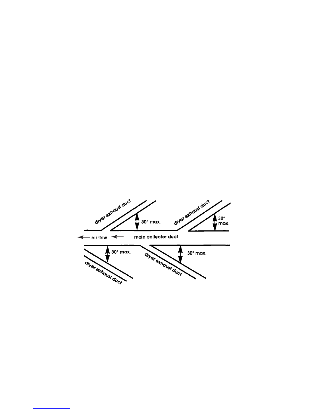
MULTIPLE DRYER VENT
INSTALLATION
A main exhaust vent can be used for exhausting a group of dryers. The main exhaust vent
should be sized to remove 200 CFM of air per
dryer.
Large-capacity lint screens of proper design
may be used in the main exhaust vent if checked
and cleaned frequently.
The room where the dryers are located should
have makeup air equal to or greater than the
CFM of all the dryers in the room.
An exhaust hood should cap the exhaust vent
to prevent exhausted air from returning into the
dryer. The outlet of the hood must be at least
12″ (30.5 cm) from the ground or anything else
that may restrict flow of exhaust air. If an
exhaust hood cannot be used, the outside end
of the main vent should have a sweep elbow
directed downward.
A Back-draft Damper Kit, #3391910, is available from your Whirlpool dealer and should be
installed in each dryer's exhaust vent to prevent exhausted air from returning into the dryers, and to keep individual exhausts in balance
within the main exhaust vent. Unobstructed air
openings are required.
Each exhaust vent should enter the main vent
at an angle pointing in the direction of the
airflow.
Vents entering from the opposite side should
be staggered to reduce the exhausted air from
interfering with the other vents. The maximum
angle of each vent entering the main vent
should be no more than 30 degrees. Keep air
openings free of dry cleaning fluid fumes. Fumes
create acids which, when drawn through the
dryer heating units, can damage dryers and
loads being dried. A clean-out cover should be
located on the main exhaust vent for periodic
cleaning of the exhaust system.
2-14
Page 29
Whirlpool
Pt #3391910
2-15
Page 30

INSTALLING THE DRYER
WARNING
Explosion Hazard
Keep flammable materials and vapors,
such as gasoline, away from dryer.
Place dryer at least 18 inches (45.8 cm)
above the floor for a garage installation.
Failure to do so can result in death,
explosion, or fire.
2. Place two of the cardboard corners from
the carton on the floor in back of the dryer.
Firmly grasp the body of the dryer, and
gently lay it on its back on the cardboard
corners.
3. Look at the ridges on one of the leveling
legs for a diamond marking. That is how far
the leg is supposed to go into the hole.
4. Start to screw the leveling legs into the
holes by hand. (You can use a small amount
of liquid detergent to lubricate the screw
threads so it is easier to turn the legs.) Use
a 1″ wrench or socket wrench to finish
turning the legs until you reach the diamond
mark, then stand dryer up on its feet.
NOTE: Slide the cardboard or hardboard under the dryer before moving it across any
flooring, to avoid damaging the floor covering.
WARNING
Excessive Weight Hazard
Use two or more people to move and
install dryer.
Failure to do so can result in back or
other injury.
1. Remove the tape from the front corners of
the dryer. Open the dryer and remove the
literature and parts packages. Wipe the
interior of the drum thoroughly with a damp
cloth.
5. Move the dryer close to its final position.
Remove the cardboard or hardboard from
under the dryer.
At this time, proceed to either “Gas Dryers” or
“Electric Dryers” to complete the installation.
2-16
Page 31

GAS DRYERS
1. Remove red cap from gas pipe.
2. Connect the gas supply to the dryer. For
L.P. gas installations, be sure to use pipejoint
compound that is resistant to the action of
L.P. gas. If flexible metal tubing is used, be
certain there are no kinks in the tubing.
3. If it is necessary to open the toe panel for
service, use a putty knife to press on the toe
panel locks, located at the top corners of
the panel. Pull downward on the toe panel
to open it. The toe panel is hinged at the
bottom.
4. Open the shutoff valve in the gas supply
line.
5. Use a non-corrosive leak detection fluid to
check for leaks. Bubbles around connections will indicate a leak.
NOTE: Never test for gas leaks with a flame.
6. If a leak appears, shut off gas valve controls
and adjust connections. Then check connections again. Close toe panel. All connections must be wrench tightened.
NOTE: The dryer door must be closed for the
dryer to operate. When the door is open, the
dryer will stop, but the timer will continue to run.
To restart the dryer, close the door, and push
the START button.
7. Connect the exhaust vent system to the
dryer exhaust outlet and the exhaust hood,
using 4″ (10.2 cm) clamps. Use caulking to
seal the exterior wall opening around exhaust hood.
8. Carefully move the dryer into its final position. Place a level on top of the dryer, first
side-to-side, then front-to-back. If the dryer
is not level, adjust the legs up or down until
it is level.
9. If the burner does not ignite and you can
feel no heat inside the dryer, shut off the
dryer for five minutes. Check to make sure
that all of the gas supply valve controls are
on, and that the electrical cord is plugged in.
Repeat this five-minute test.
10.If the drying time is too long, make sure that
the lint screen is clean, and there is no
obstruction to airflow, (i.e. kinked venting,
foreign material in vent, vent hood stuck
closed, or vent tubes too long; see page
2-13).
11.Lift the service door up at the back and
remove it from the metercase. Install the
chosen money acceptor, as instructed in
the appropriate money acceptor section of
this Job Aid.
2-17
Page 32
ELECTRIC DRYERS
WARNING
Fire Hazard
Use a new UL approved 30 ampere
power supply cord.
Use a UL approved strain relief.
Disconnect power before making
electrical connections.
It is the personal responsibility and obligation
of the customer to contact a qualified electrician to assure that the electrical installation is
adequate and in conformance with the National Electrical Code, ANSI/NFPA 70*, or with
CAN 1-B149 installation codes**, and all local
codes and ordinances.
Copies of the standards listed above may be
obtained from:
* National Fire Protection Association
One Batterymarch Park
Quincy, Massachusetts 02269
** CSA International
8501 East Pleasant Valley Road
Cleveland, Ohio 44131-5575
Connect neutral wire (white or center
wire) to center terminal (silver).
Ground wire (green or bare wire) must
be connected to green ground connector.
Connect remaining 2 supply wires to
remaining 2 terminals (gold).
Securely tighten all electrical
connections.
Failure to do so can result in death, fire,
or electrical shock.
Observe all governing codes and ordinances.
If codes permit and a separate ground wire is
used, it is recommended that a qualified electrician determine that the ground path is adequate.
A four-wire or three-wire (Canada: four-wire
only), single-phase, 120/240 volt, 60-Hz, AConly electrical supply (or four-wire or threewire, 120/208- volt, if specified on the model/
serial rating plate) is required on a separate,
30 ampere circuit, fused on both sides of the
line. A time-delay fuse or circuit breaker is
recommended.
Grounding Instructions
1. This appliance must be grounded. In the
event of malfunction or breakdown, grounding will reduce the risk of electric shock by
providing a path of least resistance for
electric current.
2. For grounded cord-connected units:
a) When using a power supply cord, the
plug must be plugged into an appropriate outlet that is properly installed and
grounded in accordance with all local
codes and ordinances.
b) This type of dryer is manufactured with
the cabinet-ground conductor connected to the NEUTRAL (center) of the
wiring harness at the terminal block. If
local codes DO NOT permit this type
of connection, use the instructions for
the four-wire U.S. connection.
Canadian models are equipped with a fourwire, 30-amp rated flexible-type power cord.
The power cord must be plugged into a mating 30-amp receptacle. (NEMA type 14-30R).
2-18
Page 33

3. For permanently connected (or hard-
wired) units:
a) This appliance must be connected to a
grounded metal, permanent wiring system; or an equipment-grounding conductor must be run with the circuit conductors and connected to the equipment-grounding terminal or lead on the
appliance.
4. For Canadian installations:
a) Use a new UL-approved power supply
cord rated 240-volt min., 30 amperes
and marked for use with a clothes dryer.
IMPORTANT: Improper connection of the
equipment-grounding conductor can result in a
risk of electric shock. Check with a qualified
electrician or service representative or personnel if you are in doubt as to whether the appliance
is properly grounded. Do not modify the plug
provided with the appliance. If it will not fit the
outlet, have a proper outlet installed by a qualified
electrician.
2-19
Page 34
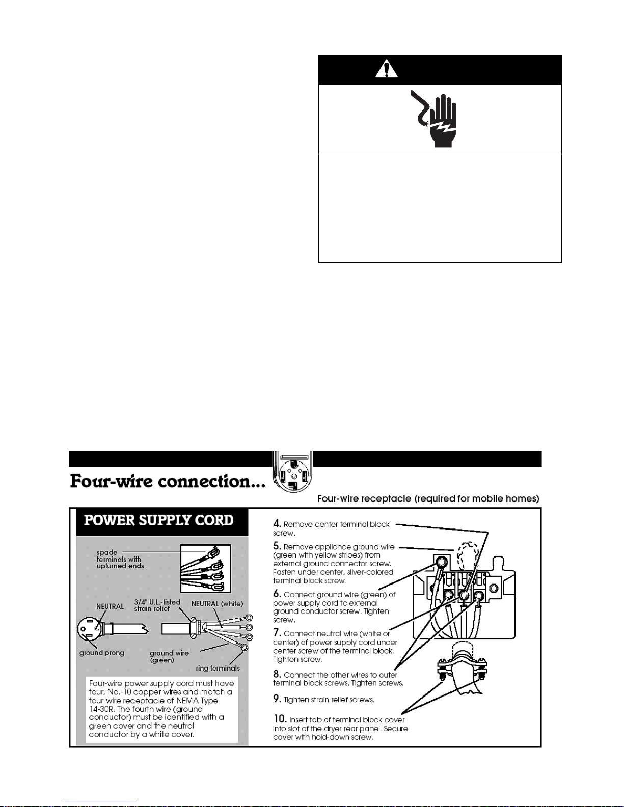
Wiring The Dryer
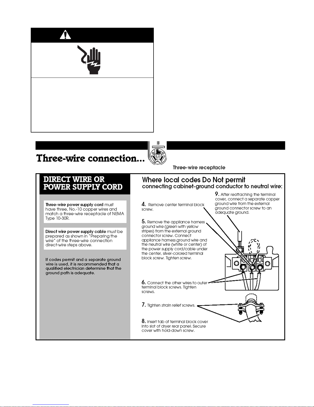
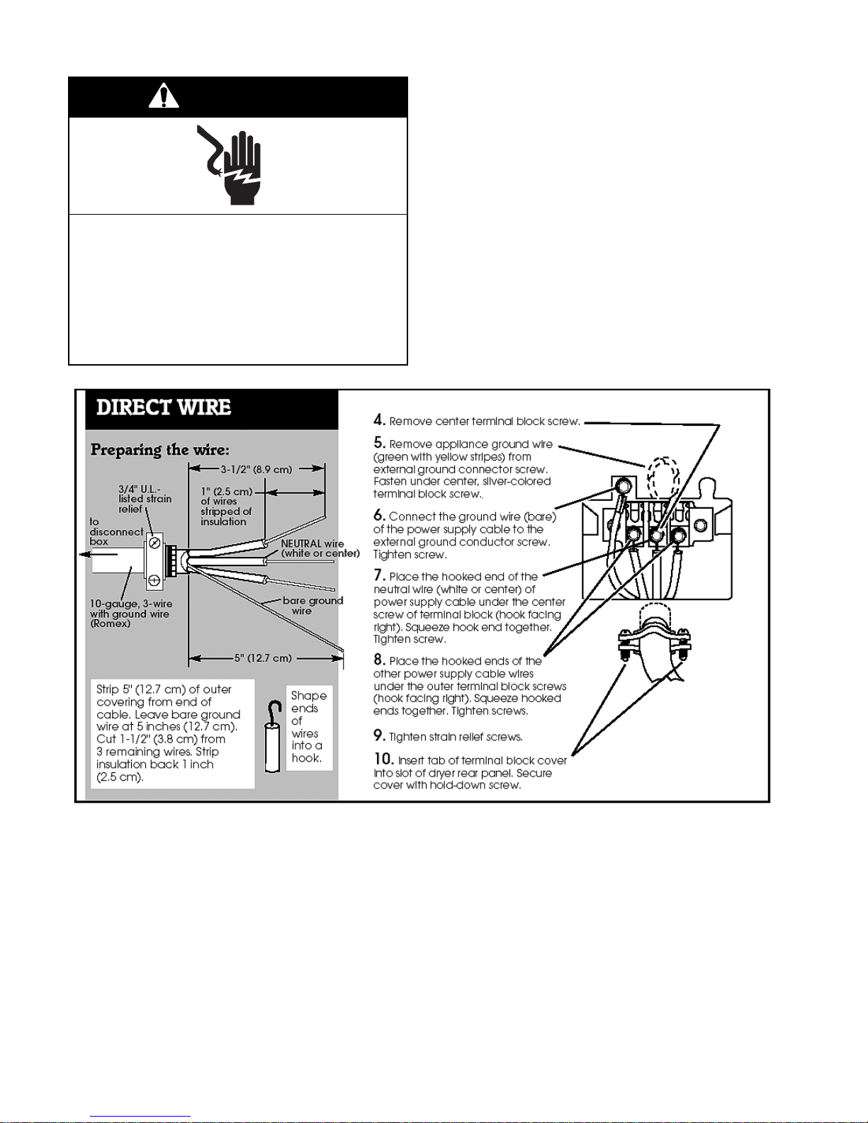
Complete the dryer installation by using one of
the following three instructions for your type of
electrical connection:
• 4-Wire Method (Preferred)
• 3-Wire Method (If 4-Wire Is Not Available)
on Page 2-21.
• Direct-Wire Method (Wire Ends Hooked)
on Page 2-22.
WARNING
Electrical Shock Hazard
Disconnect power before servicing.
Replace all parts and panels before
operating.
Failure to do so can result in death or
electrical shock.
4-Wire Method
1. Disconnect power before servicing.
2. Remove the hold-down screw and terminal
block cover.
3. Assemble a 3/4″ U.L.-Listed strain relief
(U.L. marked on strain relief) into the hole
just below terminal block opening. Tighten
the strain relief screws only enough to hold
the 2 clamp sections together. Install the
power supply cord/cable through the strain
relief.
2-20
Page 35
WARNING
Electrical Shock Hazard
Disconnect power before servicing.
Replace all parts and panels before
operating.
Failure to do so can result in death or
electrical shock.
3-Wire Method
1. Disconnect power before servicing.
2. Remove the hold-down screw and terminal
block cover.
3. Assemble a 3/4″ U.L.-Listed strain relief
(U.L. marked on strain relief) into the hole
just below terminal block opening. Tighten
the strain relief screws only enough to hold
the 2 clamp sections together. Install the
power supply cord/cable through the strain
relief.
2-21
Page 36
WARNING
Electrical Shock Hazard
Disconnect power before servicing.
Replace all parts and panels before
operating.
Failure to do so can result in death or
electrical shock.
Direct-Wire Method (U.S.A. Only)
1. Disconnect power before servicing.
2. Remove the hold-down screw and terminal
block cover.
3. Assemble a 3/4″ U.L.-Listed strain relief
(U.L. marked on strain relief) into the hole
just below terminal block opening. Tighten
the strain relief screws only enough to hold
the 2 clamp sections together. Install the
power supply cord/cable through the strain
relief.
2-22
Page 37
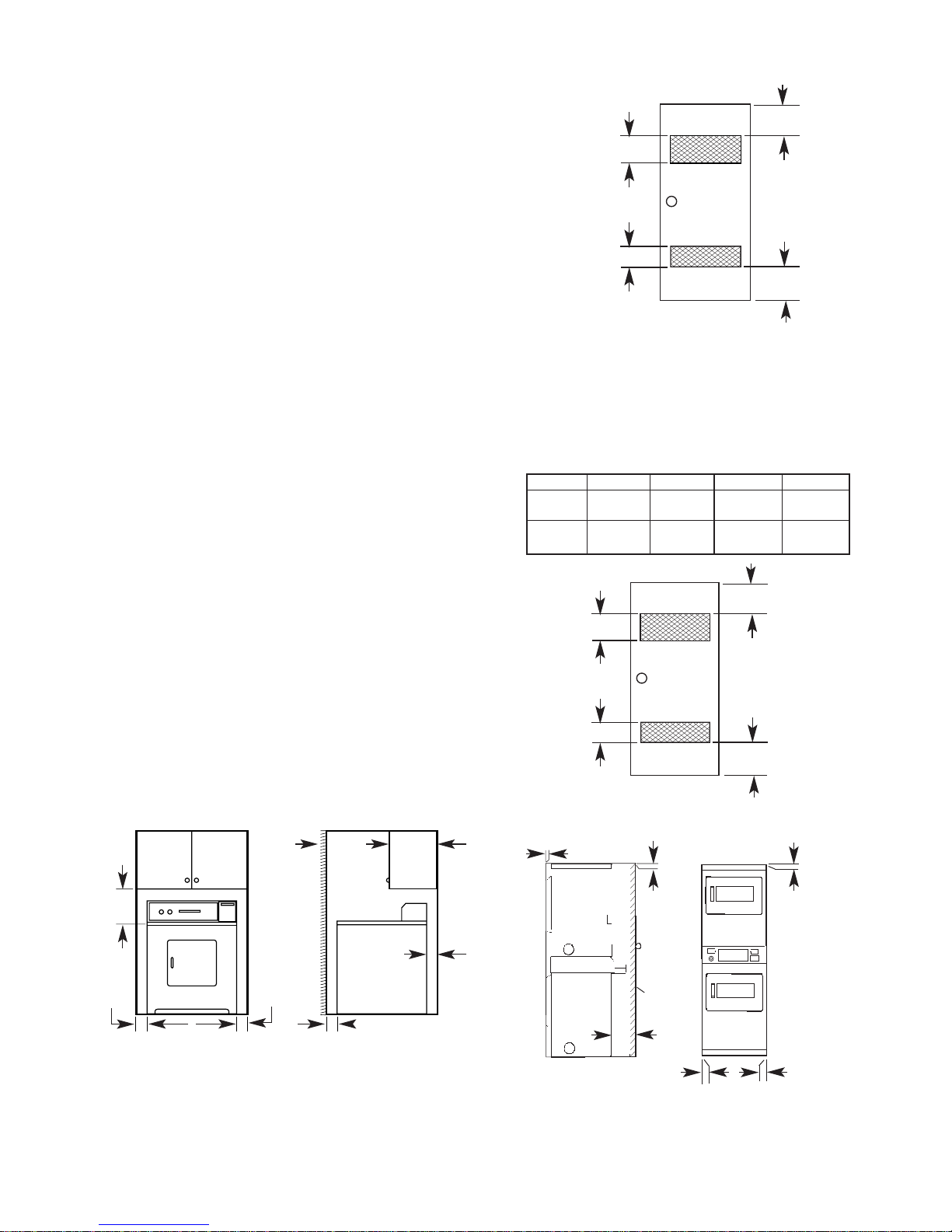
RECESSED AREA AND
CLOSET INSTALLATIONS
This dryer may be installed in a recessed area
or closet. Detailed space requirements for recessed area and closet installations can be
found on the label on the back panel of the
dryer.
The installation spacing is in inches and is
minimum allowable. Additional spacing should
be considered for ease of installation, servicing
and compliance with local codes and ordinances.
If closet door is installed, the minimum unobstructed air openings in top and bottom is
required. Louvered doors with equivalent air
openings are acceptable. Companion appliance spacing should be considered.
FOR CLOSET INSTALLATIONS, TO PREVENT
LARGE AMOUNTS OF LINT AND MOISTURE
FROM ACCUMULATING, TO MAINTAIN DRYING EFFICIENCY, AND TO PREVENT EXPOSURE TO POSSIBLE HEALTH HAZARDS,
THE DRYER MUST BE EXHAUSTED OUTDOORS.
Recessed non-exhausted installation must use
only the rear exhaust position and Exhaust
Deflector Kit, #3391278, is required.
Shelf or cabinet is not permitted above dryer
when non-exhausted. No other fuel-burning
appliance may be installed in the same closet.
3" (7.6 cm)
48 sq. in. **
(310 sq. cm)
Front View
24 sq. in. **
(155 sq. cm)
* Additional clearances may be required for wall, door
and floor moldings if external exhaust elbow is used.
** Opening is minimum for closet door. Louvered door
with equivalent air openings is acceptable.
closet
door
3" (7.6 cm)
Stack Dryers
Minimum Installation Clearances
Recessed 0 in 0 in 6 in
Closet 0 in 0 in 0 in 7 in
48 sq. in.
(310 sq. cm)
Front View
24 sq. in.
(155 sq. cm)
Back Sides Top Front
(0 cm) (0 cm) (15.2 cm)
(0 cm) (0 cm) (0 cm) (17.8 cm)
3" (7.6 cm)
closet
door
3" (7.6 cm)
—
Freestanding Dryers
Closet
Door
15″ **
(38 cm)
0″ *0″ *
Recessed Front View Side View
14″
(35 cm)
max.
0″ *
1
″ (2.5 cm)
2-23
Opening is minimum for closet door. Louvered
door with equivalent air openings is acceptable.
0" (0 cm)
0"
(0 cm)
closet
door
7"
(17.8 cm)
0" (0 cm)
Closet Side View
Additional clearances may be required for wall, door
and floor moldings if external exhaust elbow is used.
Recessed Front View
6"
(15.2 cm)
0"
(0 cm)
Page 38

MOVING THE DRYER
MAINTENANCE INSTRUCTIONS
Gas Dryers
1. Unplug dryer or disconnect power.
2. Turn off gas supply to dryer.
3. Disconnect the gas pipe and fittings from
the dryer, then cap the gas supply line.
4. Tape the open end of the dryer gas pipe.
5. Make sure the leveling legs are secure in
the dryer base.
6. Tape the dryer door and the lint screen.
Electric Dryers
1. Unplug dryer or disconnect power.
2. Disconnect the power supply cord or cable
from the dryer terminal block.
3. Make sure the leveling legs are secure in
the dryer base.
4. Tape the dryer door and the lint screen.
1. Clean the lint screen after each cycle.
2. Keep the dryer area clear and free of combustible materials, gasoline, and other flammable vapors and liquids.
3. Do not obstruct the flow of combustion and
ventilation air from inside the dryer cabinet.
4. Lint should be removed from the ducting
every two years, or more often depending
on dryer usage.
2-24
Page 39

MONEY ACCEPTOR INSTALLATION
ADVANTECH models come from the factory
without money acceptors installed. The end
user must install the money acceptor or combination of acceptors of their choice. Money
acceptors are available in three basic varieties,
coinslides, coindrops and SMART Cards. The
ADVANTECH control can accept inputs from
all of these devices.
The control can be configured to operate without a money acceptor, or have a coinslide/
coindrop with an auxiliary interface, connected
(card reader) at the same time. With multiple
money acceptor installations, some features of
ADVANTECH may be limited by the acceptor's
capabilities. For example, if a coinslide is used
on a dryer, the top-off purchase option is limited to the full amount of the coinslide.
Whirlpool does warranty the proper operation
of the control system when external connections are made as described within this document. External circuits may induce EMI (electromagnetic interference) which could result in
improper operation of the control system. It is
the responsibility of the money acceptor manufacturer to insure proper operation of the auxiliary interface device with the ADVANTECH
control. Product modifications void the Whirlpool warranty.
The money acceptor type installed must be
programmed into the control either manually or
through use of the ADVANTECH management software and the PDA. Additionally the
vend-amount of the money acceptor must
match the vend-price programmed into the
control. For information on setting vend-price
and the money acceptor type using
ADVANTECH Management Software and
Palm, consult the Software Service Manual,
Part #8524743.
If the washer or dryer is to be used without the
ADVANTECH Management Software and
Palm, infrared (IR) functionality must also be
disabled to prevent unauthorized access to the
control settings.
2-25
Page 40
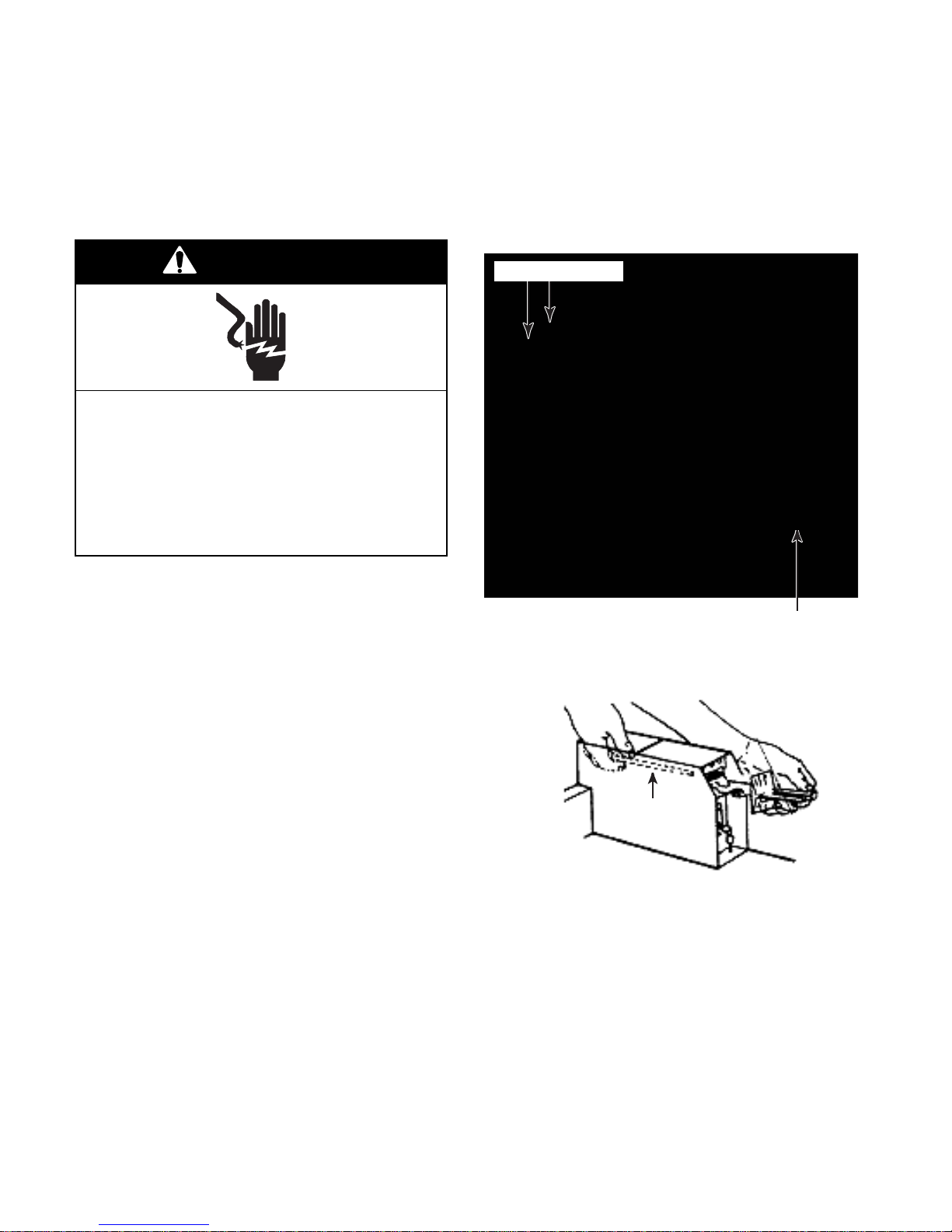
COINSLIDE INSTALLATION,
WASHERS & FREESTANDING
DRYERS
Check the electrical requirements. Make sure
that you are using the correct electrical supply,
and the recommended grounding method.
5. With the coinslide still free, connect the two
harness wires to the coinslide switch, and
the green wire to the bottom of the extension.
6. Insert the coinslide into the metercase, and
attach the green ground wire to the metercase.
WARNING
Electrical Shock Hazard
Disconnect power before servicing.
Replace all parts and panels before
operating.
Failure to do so can result in death or
electrical shock.
1. Unplug or disconnect electrical power.
2. Unlock and remove the coinbox service
access panel.
3. Unpack the coinslide and extension. If necessary assemble the coinslide extension
onto the coinslide. Coinslides and extensions are available from the manufacturers
of these devices.
Wire Connectors
Coinslide Into Metercase
7. Secure the coinslide to the metercase with
the coinslide mounting bolt.
4. Set the coinslide to the desired vend-price
using the instructions provided with the
coinslide.
Bolt
8. Replace the coinbox service access panel.
9. Reconnect electrical power.
10.Follow the appropriate procedure for either
manual or Palm
setup.
2-26
Page 41
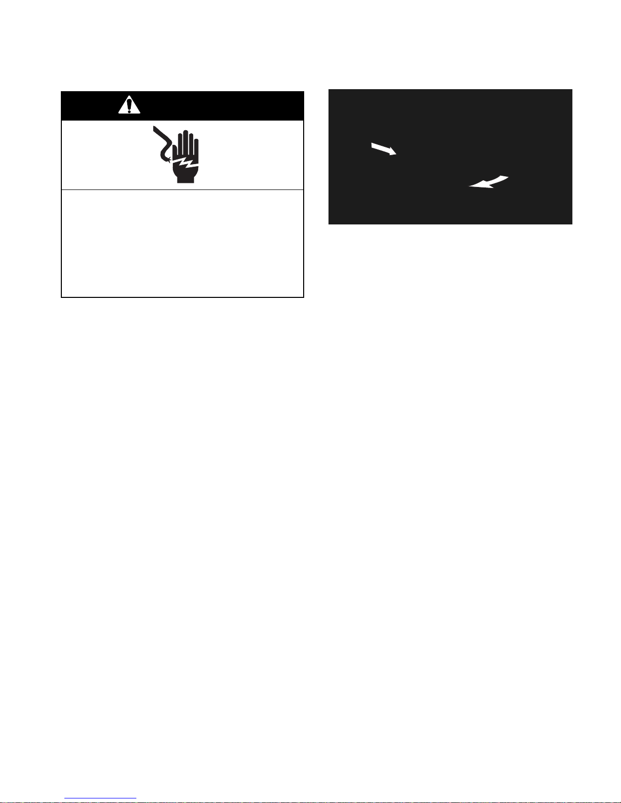
COlNSLIDE INSTALLATION,
CSP STACK DRYERS
WARNING
Electrical Shock Hazard
Disconnect power before servicing.
3. To remove the console, pull the right end
out, and slide it away from the collar.
Replace all parts and panels before
operating.
Failure to do so can result in death or
electrical shock.
Follow these instructions to ensure proper electrical grounding of the coinslide unit.
1. Unplug or disconnect electrical power.
2. Unlock the cam lock on the right side of the
console.
NOTE: Make sure that all wiring harness connections are secure prior to closing the console
after servicing or installing money acceptors.
4. Perform steps 4 through 7 on page 2-26.
NOTE: A stacked dryer uses collar openings for money acceptors instead of a
metercase.
5. Make sure all harness connections are
properly connected and reinstall the console.
2-27
Page 42

2-28
Page 43
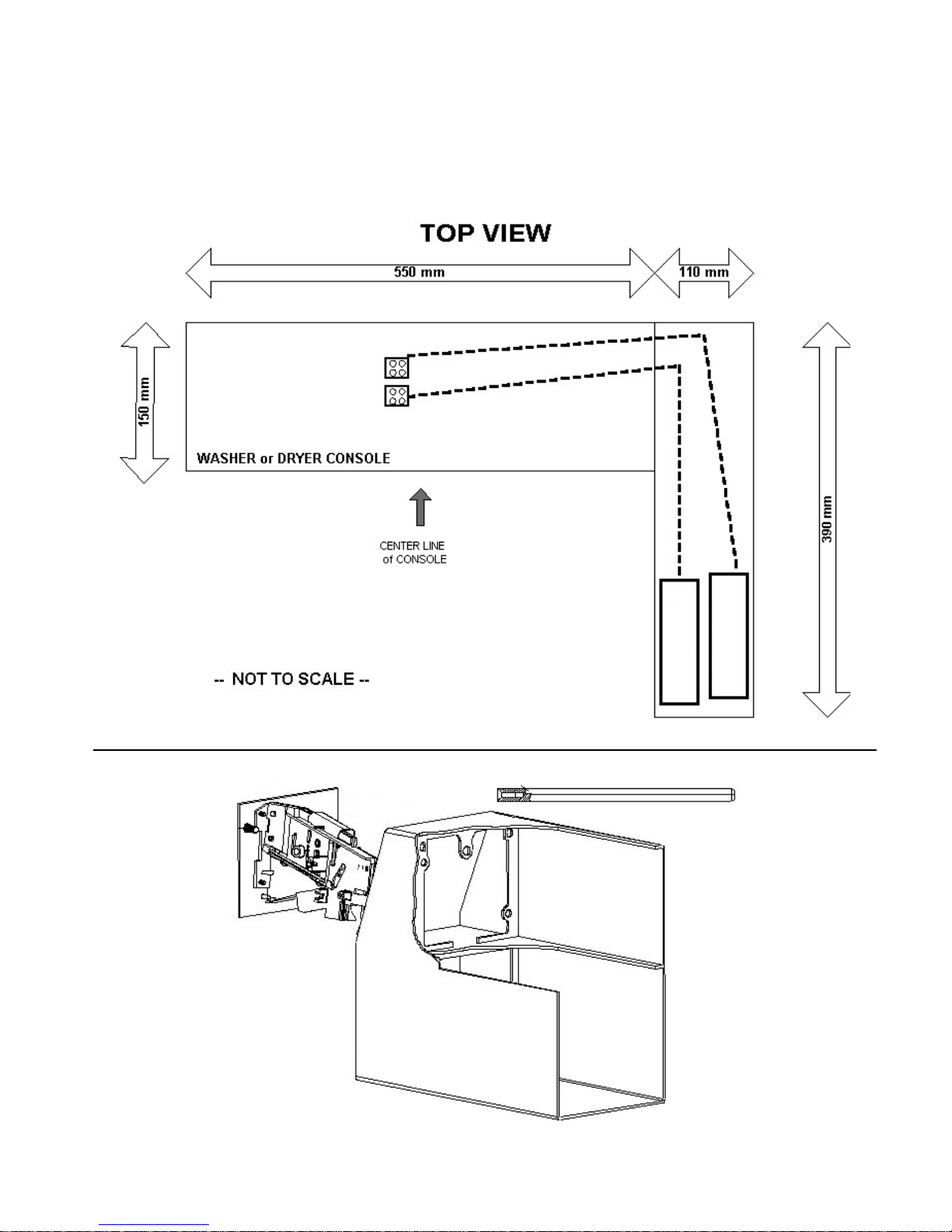
6. For single coindrops, (see the top illustration), plug the harness connector into
coindrop COIN 1 position. For dual
coindrops plug the lower value denomination drop into COIN 1, & higher value coin
into COIN 2 position.
P-12 DROP 2
P-10 DROP 1
7. Mount the coindrop into the metercase using the mounting screws/bolts included with
the coindrop kit (see the bottom illustration).
Bolt
$0.25
COIN DROP #1
COIN DROP #2
$1.00
2-29
Page 44
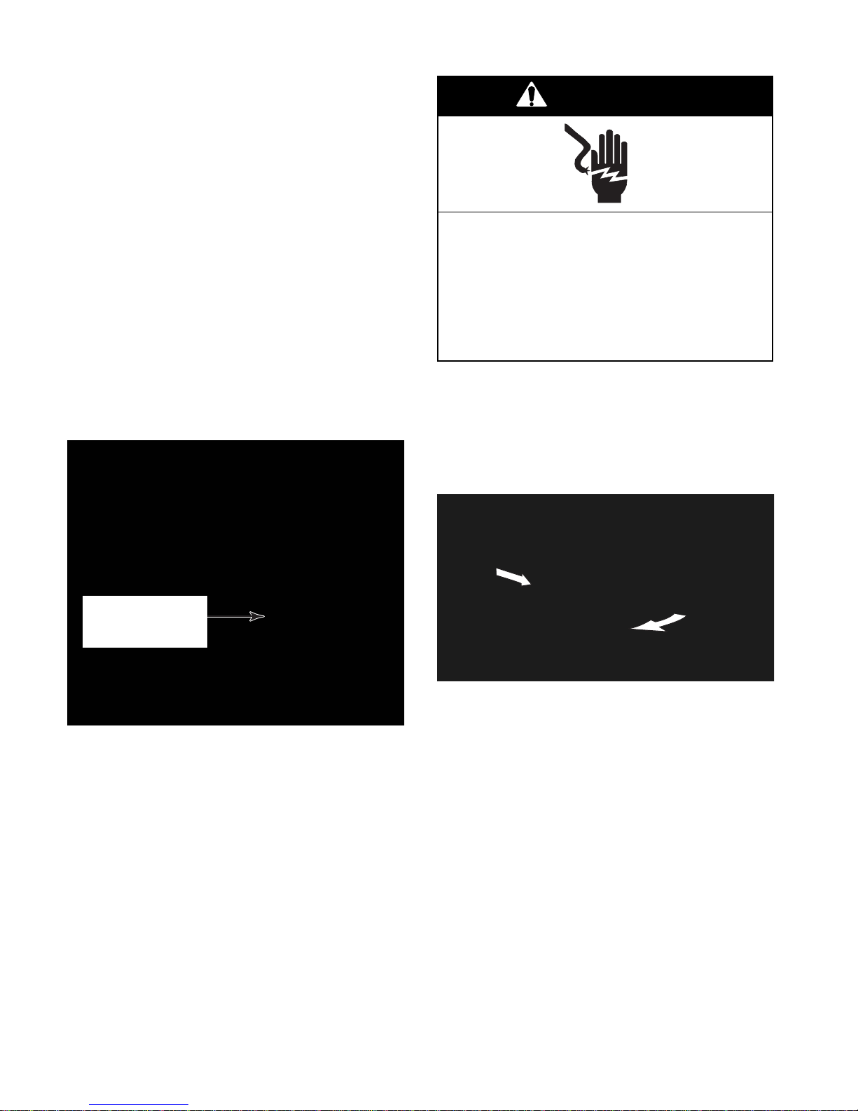
COlNDROP INSTALLATION,
CSP STACK DRYERS
ADVANTECH stack dryers are equipped with
2 control boards, one per dryer. Money acceptors (not included) for the upper and lower
dryer can be of different types i.e. upper
coinslide, lower coindrop, lower coindrop, upper SMART Card, etc.
When installing SMART Card readers or
coindrops, it is very important to thread the
harness from the proper board to the collar
money acceptor opening for the desired dryer
(upper or lower).
The upper dryer (right money acceptor opening) is controlled by the board farthest back in
the collar assembly. The front board will control
the lower dryer (left collar opening).
WARNING
Electrical Shock Hazard
Disconnect power before servicing.
Replace all parts and panels before
operating.
Failure to do so can result in death or
electrical shock.
1. Unplug or disconnect electrical power.
2. Unlock the cam lock on the right side of the
console.
3. To remove the console, pull the right end
out, and slide it away from the collar.
Coindrop Into
Upper Opening Of
Collar Assembly
NOTE: Make sure that all wiring harness connections are secure prior to closing the console
after servicing or installing money acceptors.
4. Perform steps 2 through 4 on page 2-28.
5. Thread the coindrop harness in through the
upper metercase opening, then to the console following the routing of the factory
coinslide harness.
2-30
Page 45

6. Install the coindrop into the upper opening
of the collar assembly using the nuts supplied with the coindrop kit. A deep socket
and an extension will facilitate tightening
the mounting screws closest to the outside
of the dryer.
7. Reinstall the console
8. Reconnect the electrical power.
9. Follow the appropriate procedure for either
manual or Palm
setup.
2-31
Page 46
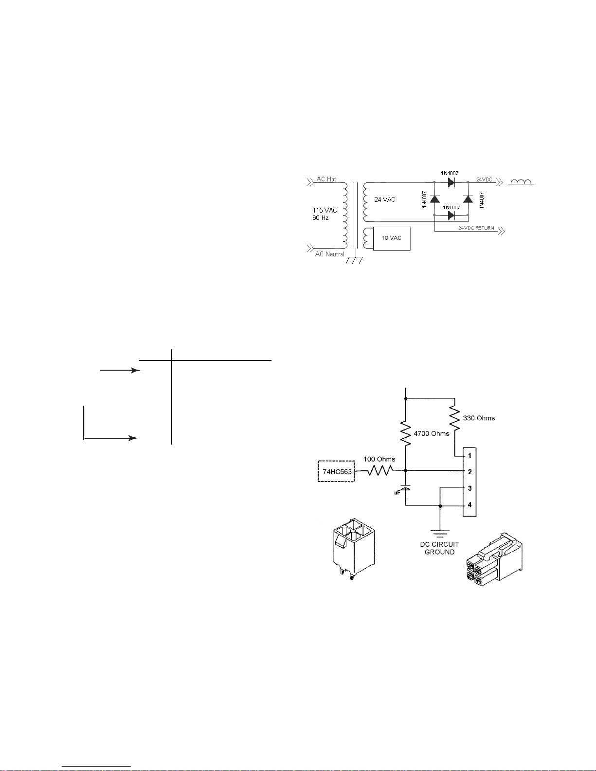
AUXILIARY DEVICE OVERVIEW
INSTALLATION, WASHERS AND
FREESTANDING DRYERS
Auxiliary devices include but are not limited to
SMART Card devices, remote monitoring stations, Internet monitors, distributed money terminals and other transaction stations. Currently the only commonly used auxiliary device
is a SMART Card. As more devices become
common, additional descriptions will be provided.
If the Auxiliary device is a SMART card unit, the
card acceptor can physically reside in the location normally used by a coinslide or coindrop
mechanism. Alternately, a washer and dryer
model is offered without a metercase (full width
console model), but provides a mounting location in the console for a SMART Card reader.
Auxiliary Communications Interface
Pinout Chart (P11 On The Board)
Pin Function
1 DC Power Return
2 DC Power
3 No Connection
4 Signal Input
5 Signal Output
6 Signal Ground
NOTE: When the thermal fuse opens the control must be replaced! Prior to installation of the
new control all auxiliary devices should be
checked per manufacturers testing procedures
to prevent control failure. Additionally the water
valve on washers and the bias heater circuits
should also be tested (see “Component Testing” in section 5).
CARD READER CIRCUIT
The +5 VDC and DC circuit ground indicated
below are isolated from the AC line by a UL
Class II transformer. No connection to earth
ground or cabinet ground is to be made by the
coindrop circuit. If a circuit other than an opto
beam interrupter is used, for example a microprocessor controlled unit, the circuits must
remain electrically isolated from one another.
COINDROP CIRCUITS
AT P10 AND P11
Security is only provided by physical access to
the auxiliary communications port. There are
no security codes imposed between the control and the auxiliary device. Therefore, the
auxiliary device must provide for its own security layer of protection.
The auxiliary device connection on the control
board features a power output enabling device
to be connected to the control without requiring
an external low voltage power source (extra
transformer). This helps reduce the end user
cost of such devices. The transformer contains
an internal one-time use thermal fuse at the
primary, which opens when current draw is
greater than the 200-mA limitation. An open
thermal fuse not only disables the entire auxiliary power supply but also power to the control.
2-32
Molex brand
#39-29-9046
Header on the
controller
0.01
Molex brand Mini-Fit Jr. Dual
Row Receptacle Part #39-01-3048
four circuits UL 94V-0 Terminal
Part #44485-1211 18-24 AWG.
The receptacle provided with the
coindrop device wire length will be
a minimum of 46″ from the
connector to coindrop device.
Page 47
AUXILIARY DEVICE INSTALLATION,
WASHERS AND FREESTANDING
DRYERS
For the purpose of installation instructions the
only auxiliary device detailed will be a SMART
Card reader. The SMART Card reader on all
models is connected to the auxiliary input.
When a SMART Card reader is installed, the
reader becomes the primary over the control,
and the control assumes the secondary role,
display codes are then driven by the card
reader. Codes will vary between card manufacturers. If a code is displayed in the reader
other than codes listed in this manual, consult
the maker of the card reader for additional
information.
NOTE: When routing the harness from the
card reader to the control, care must be taken
not to bundle the card reader harness with the
washer harness. If the two harnesses are
bundled together, signal interference may occur that would prevent proper card reader
operation.
Incorrect Card Reader Harness Bundling
WARNING
Electrical Shock Hazard
Disconnect power before servicing.
Replace all parts and panels before
operating.
Failure to do so can result in death or
electrical shock.
1. Unplug or disconnect electrical power.
2. Remove coinbox top access panel.
3. Unpack the SMART Card reader and wiring
harness included with the card reader kit.
4. On full-length console models, remove the
mounting screw from the factory installed
blank in the card reader opening and remove the blank.
5. Install the card reader control panel bezel
per the manufacturer instructions.
6. Install the card reader into the control panel
per the manufacturer instructions.
7. On metercase models release the coin
funnel from the metercase by prying up on
the plastic retaining clips and lifting up on
the funnel to release it.
8. Turn the funnel up, then remove the funnel
through the timer access panel.
9. Install the card reader into the adapter plate
in the upper metercase opening. Push the
card reader into the metercase, then lock it
in-place by pushing down slightly.
2-33
Page 48

10.Install the card reader retaining screws
included with the kit, or a standard coinslideretaining bolt.
11.Plug the card reader wiring harness into the
auxiliary connection at P11 on the control
board.
12.Close the control panel and reinstall the
mounting screws.
13.Reconnect the electrical power.
Card Reader
14.Follow the appropriate procedure for either
manual or Palm
setup.
NOTE: ADVANTECH machines are shipped
from the factory with the coinslide function
enabled. After installing a card reader into the
machine, the card reader (CArd) must be enabled prior to doing a machine setup (see
OWNER SETTINGS in Section 6 for the procedure).
2-34
Page 49
AUXILIARY DEVICE INSTALLATION,
CSP STACK DRYERS
ADVANTECH stack dryers are equipped with
two control boards, one per dryer. Money acceptors for the upper and lower dryer can be
different types (upper coin, lower drop, lower
coin, upper card, etc.)
NOTE: When installing SMART Card readers
or coindrops, it is very important to thread the
harness from the proper board to the collar
money acceptor opening for the desired dryer
(upper or lower).
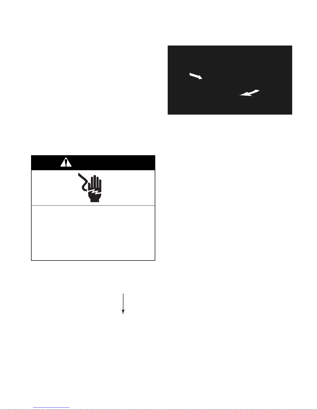
The upper dryer (right money acceptor opening) is controlled by the board farthest back in
the collar assembly. The front board controls
the lower dryer (left collar opening).
WARNING
3. To remove the console, pull the right end
out, and slide it away from the collar.
NOTE: Make sure that all wiring harness connections are secure prior to closing the console
after servicing or installing money acceptors.
4. Perform steps 2 through 4 on page 2-33.
5. Thread the card reader harness in through
the upper metercase opening, then to the
console following the routing of the factory
coinslide harness.
Electrical Shock Hazard
Disconnect power before servicing.
Replace all parts and panels before
operating.
Failure to do so can result in death or
electrical shock.
1. Unplug or disconnect electrical power.
2. Unlock the cam lock on the right side of the
console.
Lock
6. Install the card reader into the collar using
the retaining bolt supplied with the card
reader kit.
7. Reinstall the console, ensure all harness
connections are attached fully to the appropriate connectors.
8. Reconnect the electrical power.
9. Follow the appropriate procedure for either
manual or Palm setup.
NOTE: ADVANTECH machines are shipped
from the factory with the coinslide function
enabled. After installing a card reader into the
machine, the card reader (CArd) must be enabled prior to doing a machine setup (see
OWNER SETTINGS in Section 6 for the procedure).
UPPERLOWER
2-35
Page 50
ADVANTECH
CONTROL SET UP
After the appropriate money acceptor has been
installed in an ADVANTECH
washer or dryer,
the control must be configured to match the
installed device. This can be accomplished
through transferring the appropriate template
that matches the money acceptor from the
management software, 1) to a Palm
unit, then from the Palm
ADVANTECH
control board, 2) by inputting
via infrared to the
handheld
the appropriate series of manual keystrokes
through the membrane switch, 3) by inserting
the appropriate SMARD Card setup into the
newly-installed card reader. To set up the con-
trol, an ADVANTECH
product must be in-
stalled and power applied.
WARNING
Electrical Shock Hazard
Disconnect power before servicing.
Replace all parts and panels before
operating.
Failure to do so can result in death or
electrical shock.
4. The HOT temperature LED begins blinking
to confirm that the switch was pushed. The
machine's lifetime cycle count now shows
on display. Display automatically returns to
the vend-price after 1 minute of inactivity.
Accessing The Service Mode For
Full Console Models
1. Unplug or disconnect electrical power.
2. Remove the two T-15 Torx screws from the
console.
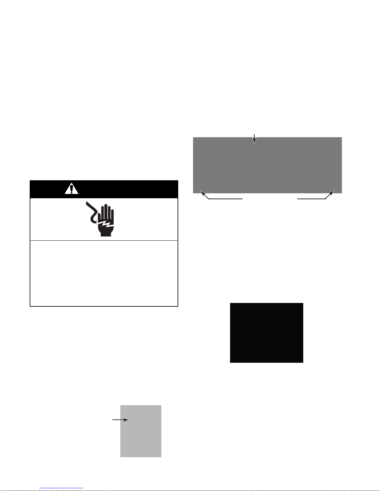
Temperature LEDs
T-15 Torx Screws
NOTE: On electric dryers, the control panel
should only be open with the power cord cover
in place. If the power cord cover is removed
with the console in the service position and
power is applied, there is a risk of shock and
product damage.
3. Rotate the console back on its two hinges
into the service position.
4. Press and release service switch S1 on the
control board.
CONTROL SETUP:
MANUALLY SETTING THE CONTROL
Accessing The Service Mode For
All Metercase Models
1. Unplug or disconnect electrical power.
2. Remove the service access door on top of
the metercase. The door may be locked
and require a key.
3. Push and release the rocker switch located
inside the metercase.
Rocker
Switch
5. The HOT temperature LED will begin flashing to confirm that the switch was pushed.
The machine's lifetime cycle count now
shows on display. The display automatically returns to vend-price after 1 minute of
inactivity.
2-36
Page 51
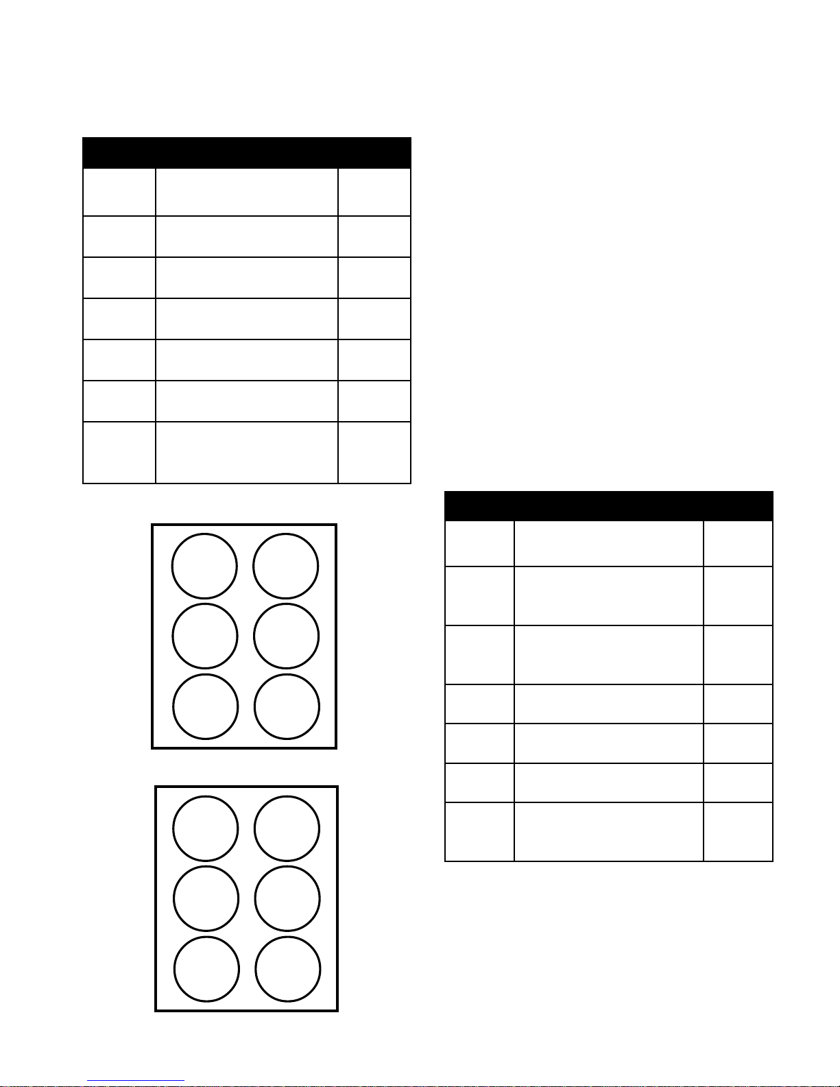
6. Keypads are now re-mapped for navigating
Dryer
Keypad
HOT
1
Increase the setting value.
Push and hold the keypad for a
fast increase.
HIGH
1
WARM
2
Decrease the setting value.
Push and hold the keypad for a
fast decrease.
MEDIUM
2
COLD
3
NO FUNCTION
NORMAL
4
NO FUNCTION
GENTLE
5
NO FUNCTION
HIDDEN
6
Accept the new setting value.
The display returns to the
OWNER SETTINGS list.
START
6
KEYPAD NAVIGATION
the settings as listed in the following “Keypad Mapping” table.
KEYPAD MAPPING
7. If the service calls for a free-vend, push and
release keypad #3 (see the “Keypad Positions”). The unit is now ready for use as if
money was used. On dryers, push and
release keypad #6 to start.
Washer
Keypad
HOT 1Move up to the preceding
item on the list.
WARM
2
Move down to the
next item on the list.
COLD 3Select an item to view
the current setting.
NORMAL
4
GENTLE
5
HIDDEN
6
NO FUNCTION
NO FUNCTION
Exit OWNER SETTINGS
program. The display
returns to the cycle count.
Washer Keypad Positions
HOT
1
NORMAL
4
Dryer
Keypad
HIGH
1
MEDIUM
2
LOW
3
ON
4
OFF
5
START
6
8. If a money acceptor has been installed,
press keypad #1 to enter the “Owner Settings.”
9. Scroll through the owner settings using
keypad #1 or #2 until the proper money
acceptor is located (droP, SLidE, or CArd).
(See the OWNER SETTINGS tables in
Section 6.)
NOTE: Keypad #6 is hidden on two-speed
washers. Keypads #4, #5, and #6 are hidden
on single-speed washers.
10.Press keypad #3 to view the current setting
of the selected money acceptor. To change
the setting, use keypad #2 to toggle between 0 (disabled) and 1 (enabled).
Washer
Keypad
WARM
2
COLD
3
GENTLE
5
HIDDEN
6
Dryer Keypad Positions
HIGH
1
MEDIUM
2
LOW
3
ON
4
OFF
5
START
6
LOW
3
ON
4
OFF
5
2-37
Page 52

11.Press keypad #6 to accept the setting, and
return to the owner settings.
12.Press keypad #2 to scroll to cycle price,
then press keypad 6. The current vendprice will be displayed.
14.When the proper vend-price is displayed,
press keypad #6 to return to owner settings.
15.Press keypad #6 again to exit the setup and
return to vend-price.
NOTE: The vend-price of the coinslide or
coindrop must match the control setup.
13. Increase or reduce the cycle price desired
for the card reader, or the cycle price as
determined by the mechanical setting of
the coinslide or coindrop by pressing keypad #1 (increase) or #2 (decrease), as
shown in the “Keypad Navigation” table on
the previous page.
NOTE: Additional cycle functions may be set
at this time, such as the top-off price for dryers, or an extra charge for hot or warm water
for washers. See the OWNER SETTINGS
table in Section 6 for advanced features/
manual programming.
16.Insert the money card for card readers, or
the appropriate coins into the selected
money acceptor device to verify proper
operation.
2-38
Page 53
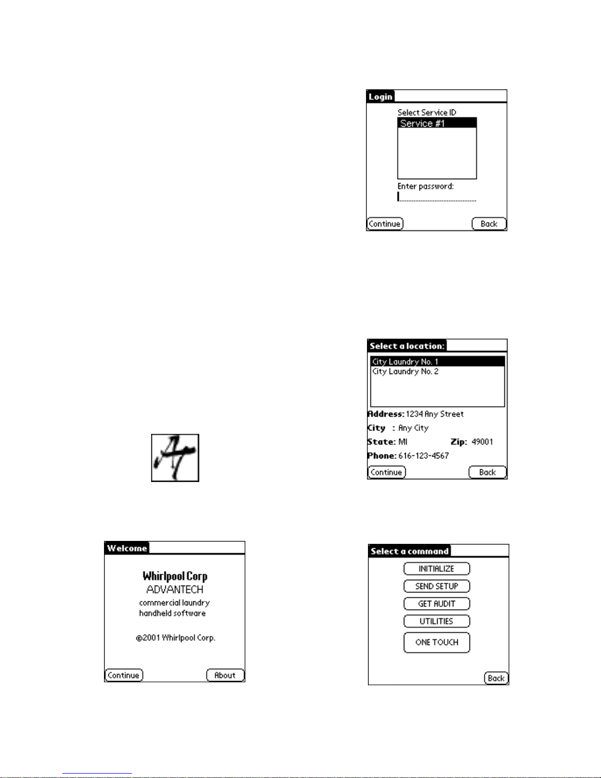
CONTROL SETUP:
HANDHELD PALM
(PDA) DEVICE
Detailed Palm enabled set up information can
be obtained from the Software User's Manual,
Part #8524743.
This section will cover the installation of a
template from the Palm to a washer or dryer.
For advanced features such as template creation requiring use of the management software, see the Software User’s Manual, Part
#8524743.
NOTE: The following procedure assumes that
security, locations and templates have already
been established using the management software program and that the selected Palm has
performed a HotSync with the management
software.
1. To start the Handheld Software, remove
the Palm handheld from its cradle and turn
it on.
6. Tap on Continue.
7. The Login screen appears.
8. Select the correct Servicer ID, and enter
the corresponding password using the
Graffiti
writing method.
9. Tap on Continue. The Select a location
window appears. Select the appropriate
location, then tap on Continue.
2. Check the battery power by pressing the
HOME button with the stylus. 50% or more
battery power is needed.
3. Using the stylus, tap the Palm handheld,
and scroll to the ADVANTECH icon.
4. Tap the ADVANTECH icon.
5. The Welcome screen will appear.
10.After logging in and selecting the appropriate location, the Select a command screen
appears.
2-39
Page 54

2-40
Page 55
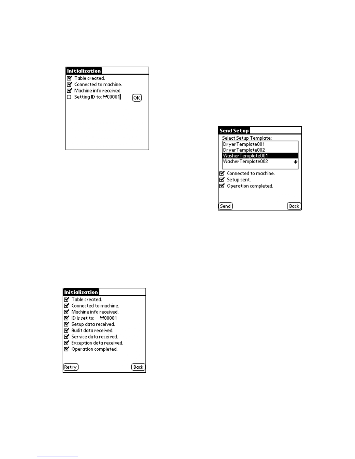
2. Verify that you are aiming at the machine's
infrared receiver then tap on OK when the
ID is correct on the screen, as illustrated
below.
Send Setup Command
The Send Setup command transfers a washer
or dryer template, created in the management
software, to a machine.
1. Aim the infrared port on the PDA at a 90°
angle to the machine's receiver.
NOTE: Machine IDs must begin with a “W” for
washer or a “D” for dryer, followed by an additional 5-digits. The handheld software suggests
a logical naming order, or if you prefer, use the
product serial number. Machine IDs must also
be unique within each location. An easy way
to keep track of machine names is to begin
with the first machine to your left as you enter
a location, and work clockwise around the
room, or physically mark the machine with a
property tag or magic marker.
3. When initialization is complete, the screen
will display Operation completed. Tap on
Back to return to the Select a command
screen.
2. Tap on Send Setup, from the Select a
command screen on the Palm
.
3. Select the appropriate Setup Template,
then tap on Send.
4. When the operation is complete, tap on
Back to return to the Select a command
menu.
5. Insert the user card or appropriate coins
into the selected money acceptor to verify
proper operation.
NOTES:
• The Management Software will not recog-
nize the setup data you assigned to the
machine until you have taken an audit and
performed a HotSync‚ operation to upload it
back to your PC.
• Remember to change the mechanical
coinslide vend-price to match any changes
made to the control board vend-price in the
setup mode.
2-41
Page 56
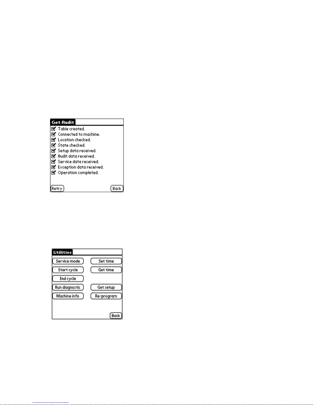
Get Audit Command
1. Aim the infrared port on the PDA at a 90°
angle to the machine's receiver.
2. Tap on Get audit, from the Select a com-
mand screen on the Palm
.
3. When audit is complete tap on Back to
return to the Select a command menu.
4. If all items are not checked on the Get audit
screen then the process was not successful, and steps 1 through 3 need to be
repeated by clicking Back on the Palm
.
• Service mode—Places the machine into
the Service Mode. This option can be used in
place of pressing the service switch on the
machine. (Refer to the Tech Sheet for more
information on placing the machine in Service Mode.)
• Start cycle—Allows the service person to
start a cycle without depositing any coins.
• End cycle—Ends the current cycle that is
running.
• Run diagnostic—Checks machine's internal data to ensure integrity.
• Machine info—Displays the processor's se-
rial number, machine ID, location ID, and
software version number.
• Set time—Sets the machine's internal clock
based on the time and date that is on the
Palm handheld. The time is set automatically during initial setup of the machine,
however use Set time if manual setup is
required.
Utilities Command
The Utilities Command is also located on the
Select a command screen, and displays options for managing the machines. Many of the
options can be accessed directly from the
control board, without the use of a Palm.
• Get time—Displays the machine's current
time and date settings.
• Get setup—Allows the service person to
“clone” a machine. For example, if a control
board needed to be replaced on a machine,
the service person could clone the setup
data from an existing machine in order to
copy the current template to the new control
board.
• Re-program—Used only when a machine
software upgrade is required. Instructions
for reprogramming will be provided when
new machine software is distributed.
2-42
Page 57

PRODUCT OPERATION
ADVANTECH SYSTEM OVERVIEW
ADVANTECH Product flexibility allows a single
washer or dryer to accept multiple payment
systems over the life of the product. This eliminates the need to purchase different SKUs
based on money acceptance requirements.
ADVANTECH allows use of multiple money
acceptors, as well as Palm
and SMART Card
accountability systems at the same time. All
ADVANTECH
models come equipped with an
auxiliary communications port for connecting
SMART Cards, Ethernet boxes, Internet controls, or additional devices. ADVANTECH does
not require that purchasers be tied to an appliance manufacturer’s proprietary card reader.
The ADVANTECH open-architecture design
allows the use of a card system that best meets
the current business requirements to be installed into the product.
Whirlpool ADVANTECH Commercial Laundry Products allow the use of a Palm handheld
device, also referred to as a “Personal Digital
Assistant” (PDA), for washer and dryer installation and setup. This includes setting special
vend-prices, washer and dryer software upgrades, and transferring data to and from a
personal computer (PC). Information is set up
on a PC using ADVANTECH Management
Software, which is then used to download
ADVANTECH Handheld Software to the
Palm. The Palm uses an infrared light beam
to communicate information contained in the
Management Software to the washer and dryer.
Before downloading the Handheld Software to
the Palm, Management Software must be
installed and running on the PC. Passwords,
machine setup, and Handheld Software are
available within the Management Software.
Detailed information about setup and installation of the ADVANTECH Management Software is available in the Software Service
Manual, Part #8524743. Additional
ADVANTECH literature can be located in the
“Literature Cross-Reference Chart” on page
1-9.
Commands for the Management Software installed on the PC are entered by using the
keyboard or mouse. Commands for the
Handheld Software are entered into the Palm
by tapping the appropriate menu on its screen,
using a stylus that is provided with the handheld
device. Occasionally you may be asked to
enter text into the Palm
using the Graffiti text
characters, or the Palm keyboard. Additional
information regarding the use of Graffiti text
and the Palm keyboard can be found in the
Palm Owner’s Manual.
3-1
Page 58

ADVANTECH PC SYSTEM & PALM REQUIREMENTS
MINIMUM PC SYSTEM
REQUIREMENTS
• Pentium 233 MHz MMX processor
• CD-ROM drive
• 32 MB of RAM
• Dedicated minimum of 2.5 GB of hard
drive space for storing report information
• One of the following operating systems:
- Windows 98 Version 4.10.2222A
(Second Edition) preferred
- Windows 98 Version 4.10.1998 (First
Edition)
- Windows 95 SR2, SR2.5
- Windows NT SP3, SP4, SP6
- Windows
ME
2
- Windows 2000 Professional, SP1
• Monitor resolution: 1024 x 768 pixels, or
higher
1
In order for the Management Software to run on the
Windows 95 operating system, Windows 95 users
must install DCOM95 before installing the Management Software. Refer to page 11 of the Software
Users Manual for DCOM95 Installation Instructions.
2
Use of Microsoft Windows ME may produce the
following error during setup: “Fatal Setup Error MDAC 2.5 is already running on the operating system
that you are running.” Click on “OK” to ignore this
message and continue the setup.
1
MINIMUM PALM HANDHELD
REQUIREMENTS
• Palm handheld computer, IIIx, or higher
• 4MB of RAM
• Palm OS 3.5.0, or higher
IMPORTANT:
The electronic controls within the
ADVANTECH laundry machines are factory
preset to accept commands from a Palm
handheld equipped with the Handheld Software. If a Palm handheld is not used, this
functionality must be disabled. Failure to disable the handheld device can result in unauthorized machine access. To manually disable
handheld functionality, go to the Important Setup Information section of the Tech Sheets
supplied with each ADVANTECH machine,
initiate a service sequence manually, and look
for the Palm Accessory setting, P ACc will be
displayed. This setting can be set to either 1,
which equals on or 0, which equals off for this
feature.
All machine usage history will be lost at time of
control board replacement.
3-2
Page 59
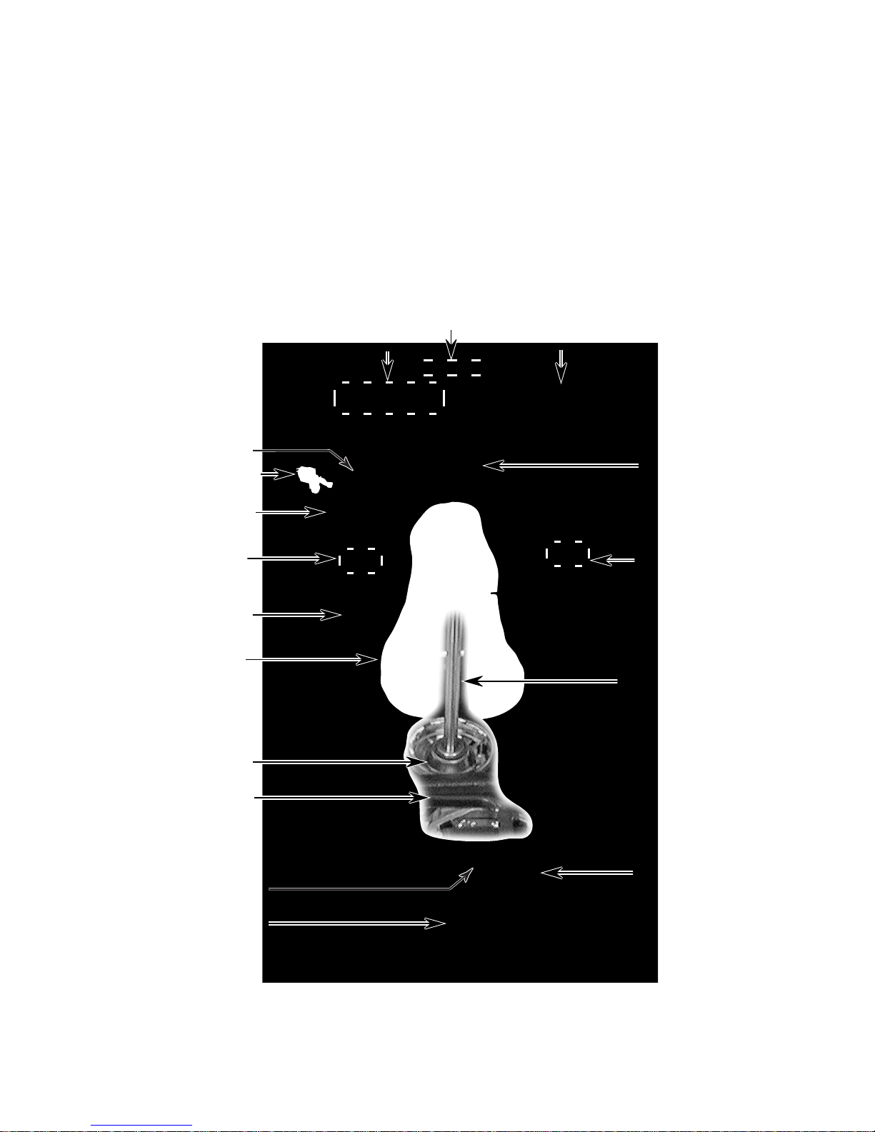
COMPONENT ACCESS
WASHERS
This section instructs the technician on how to service each component inside the ADVANTECH
Commercial Washer. The front washer components and their locations are shown below. The rear
panel components are shown, starting on page 4-22.
WASHER COMPONENT LOCATIONS
Display Board
ADVANTECH
Basket
Hidden Lid Switch
Tub Ring
Water Level Switch
(On Rear Panel)
Control Board
Card Reader
Vacuum Break
Dual Water Valve
(On Rear Panel)
Outer Tub
Agitator
Clutch
Transmission
Motor
Pump
Basket Drive
Motor Start
Capacitor
4-1
Page 60
REMOVING THE CONSOLE COMPONENTS
NOTE: The Model CAE2792K is shown in this
console removal procedure. The Model
CAE2762K uses the same components, but
without the card reader.
WARNING
Electrical Shock Hazard
Disconnect power before servicing.
Replace all parts and panels before
operating.
Failure to do so can result in death or
electrical shock.
1. Unplug washer or disconnect power.
2. Remove the two T-15 Torx screws from
the console.
Console
T-15 Torx Screws
3. Slide the console to the front of the unit
slightly, then rotate it back and place it in
the “service” position.
Card Reader
4. To remove the ADVANTECH control
board:
a) Disconnect the 6 board connectors at
P1, P2, P3, P4, P8, and P11.
b) Disconnect the green ground wire from
terminal P6.
c) Remove the six 5/16″ hex-head screws
from the board and remove the board
from the unit.
ADVANTECH Control Board
Screw (1 of 6)
P11
P8
P2
P4
P3
Ground Wire
P1
5. To remove the display board:
a) Remove the ADVANTECH
control
board (see step 4).
b) Disconnect the connector from the dis-
play board at P1.
c) Unlatch the display board from the
holder and remove it.
P1
Latch
Display Board
Control Board And Display Board
(Below Control Board)
4-2
Page 61
6. To remove the membrane switch:
a) From the rear of the unit, remove the
screw from either of the end caps.
Rear Screw
e) Bend the tabs on the membrane switch
and remove them from the slots in the
board. NOTE: Be sure to install the
new membrane switch on the board
with the ribbon cable facing the end
with the two alignment pins that are on
the opposite side of the board. Also
make sure that the ends of the two
alignment pins are in their bracket holes.
End Cap
Hinge
b) Remove the ADVANTECH control
and display boards (see steps 4 and 5).
c) Remove the two ground screws from
the green ground wires (see the photo
below).
NOTE: The membrane switch board will be
loose when you remove the bracket screws in
the next step. Be careful not to drop the board
when you remove the bracket.
d) Remove the two end cap screws from
both ends of the console bracket. Carefully lift the bracket from the console,
and remove the loose end cap and the
membrane switch board.
Ground Screws
Membrane Switch
Alignment Pin
Ribbon Cable
Membrane Switch Tabs
Backer Board
Alignment Pin
7. To remove the card reader assembly:
a) Disconnect the connector from the
ADVANTECH
ADVANTECH Control Board
P11
control board at P11.
Card Reader
End Cap Screws
Continued on the next page.
4-3
Page 62
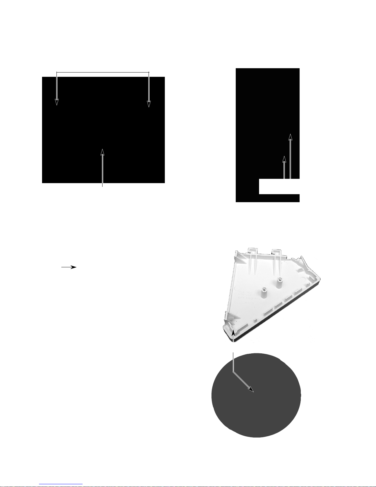
b) Remove the two screws from the card
reader assembly and remove the assembly.
Card Reader Screws
Card Reader Assembly
b) Remove the two hex-head screws from
the console support bracket, and slide
the end cap off the end of the panel.
Console Support
Bracket Screws
8. To remove an end cap from the console:
a) Remove the hex-head screw from the
back of the end cap.
Back
Screw
Left End
Cap
c) If a mounting stud is not installed on
the new end cap, remove the stud from
the old cap, and install it on the new
one.
Left End
Cap
Mounting Stud
4-4
Page 63

9. To remove the spark quencher:
NOTE: The spark quencher is an in-line
filter that is part of the main harness and
must be removed as an assembly.
a) Disconnect the harness wire connec-
tors from the components.
b) Unclip and remove the main harness
from the unit (refer to the spark
quencher Service Pointer in section 8
for complete service information).
Spark Quencher
4-5
Page 64
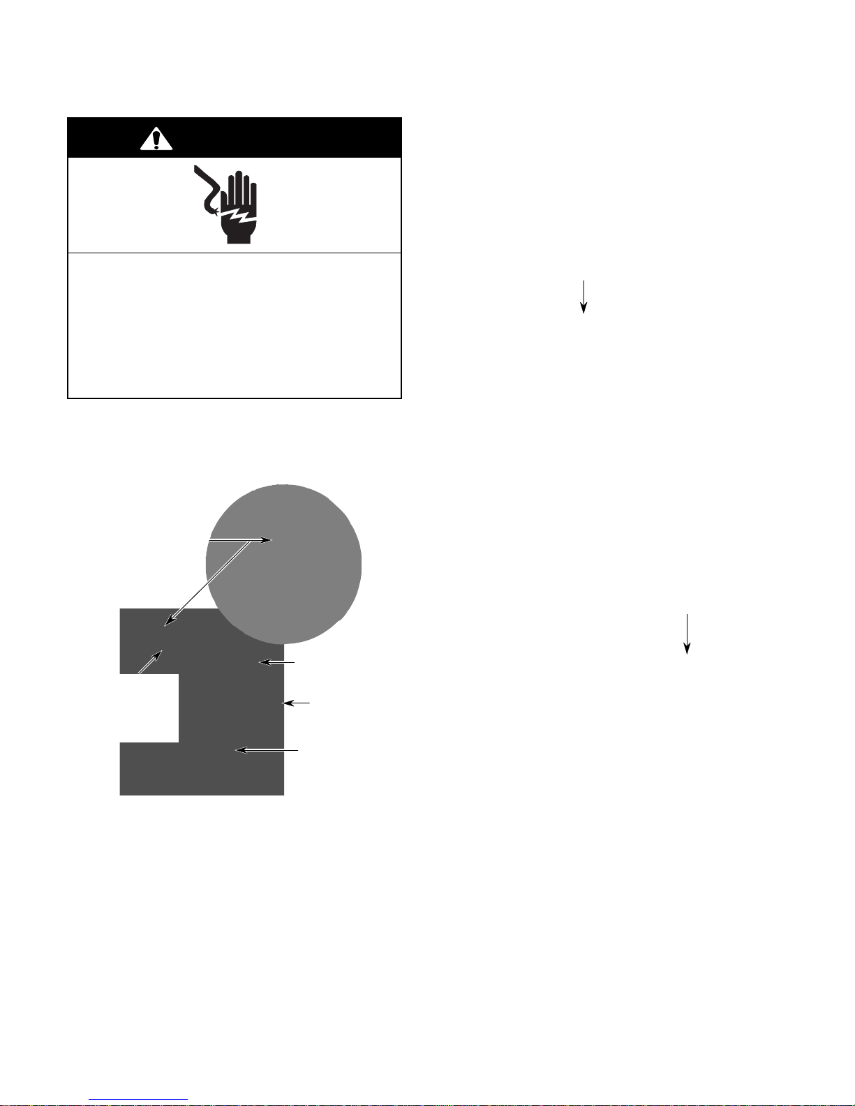
REMOVING THE MONEY ACCEPTORS & METERCASE
3. To remove the coinslide assembly:
WARNING
a) Using a 5/16″ socket, unscrew the
retaining bolt from the money acceptor, and remove the bolt from inside the
metercase.
Electrical Shock Hazard
Disconnect power before servicing.
Replace all parts and panels before
operating.
Failure to do so can result in death or
electrical shock.
1. Unplug washer or disconnect power.
2. Unlock the service access door and remove it from the top of the metercase.
Access Door
Metercase
5/16″ Retaining Bolt
b) Remove the 5/16″ hex-head screw from
the coinslide green ground wire that is
attached inside the metercase.
Ground Wire
Coinslide Switch
(inside) On
Coinslide
Extension
Coinslide
Assembly
Coinbox
4-6
Page 65

c) Lift the coinslide to release it from the
holes in the metercase, and pull it
forward out of the metercase.
d) Unplug the two wires from the coinslide
switch.
Coinslide Switch
With 2 Wires
4. To remove the card reader assembly:
a) Using a 5/16″ socket, unscrew the
retaining bolt from the money acceptor, and remove the bolt from inside the
metercase.
b) Lift and pull the card reader assembly
forward and remove it from the
metercase.
Card
Reader
Assembly
c) Position the console to its service po-
sition (see page 4-2 for the procedure).
d) If you are changing to a different type
of money acceptor, disconnect the connector from P11 on the ADVANTECH
control board, and remove the card
reader wire harness.
ADVANTECH Control Board
P11
5/16″ Retaining Bolt
e) If you are replacing a defective card
reader, disconnect the wire connector
from the card reader assembly.
Continued on the next page.
4-7
Page 66
5. To remove the coindrop assembly:
6. To remove the coinbox switch:
a) From inside the open access panel of
the metercase, remove the screws or
hex-bolts from the back of the coindrop
assembly.
b) Position the console to its service po-
sition (see page 4-2 for the procedure).
c) Disconnect the connector(s) at P10 /
COIN 1 (& P12 / COIN 2) on the
ADVANTECH
P10 (COIN 1)
P12 (COIN 2)
control board.
ADVANTECH Control Board
d) Remove the coindrop with its wire har-
ness from the unit.
a) Unlock and remove the coinbox from
the metercase.
b) Disconnect the two wires from the
coinbox switch terminals from inside
the metercase.
c) Squeeze the locking tabs on the top
and bottom of the switch body and
push the switch into the coinbox compartment of the metercase.
Coindrop
Assembly
Top Locking Tab
Coinbox Switch Wires
4-8
Page 67
7. To remove the service switch:
a) Push up on the switch body, and re-
move the switch from the retaining
bracket from inside the metercase.
b) Disconnect the two wires from the ser-
vice switch terminals.
Retaining Bracket
Service Switch Wires
8. To remove the metercase:
a) Remove the money acceptor from the
metercase.
c) Unsnap the locking arms from the bot-
tom of the coin funnel and remove the
funnel from the metercase.
d) Remove the 1/2″ hex-head screws from
the front and rear of the metercase,
then lift the metercase off the washer,
and remove it.
Coin Funnel
1/2″ Hex-Head Front
Metercase Screws
9. To remove the adapter plate:
Money
Acceptor
b) Unlock and remove the coinbox.
a) Remove the coinbox.
b) Unlock and remove the service access
door.
c) Using a ratchet with a 10″ extension
and a 3/8″ socket, remove the two hexnuts from the adapter plate through the
service access opening.
d) Remove the 3/8″ hex-nut from the top
of the coinbox opening. Pull from the
top, and remove the adapter plate.
Hex-Nuts (Behind
Adapter Plate)
Adapter Plate
Coinbox Area
Hex-Nut
4-9
Page 68

#285784
4-10
Page 69
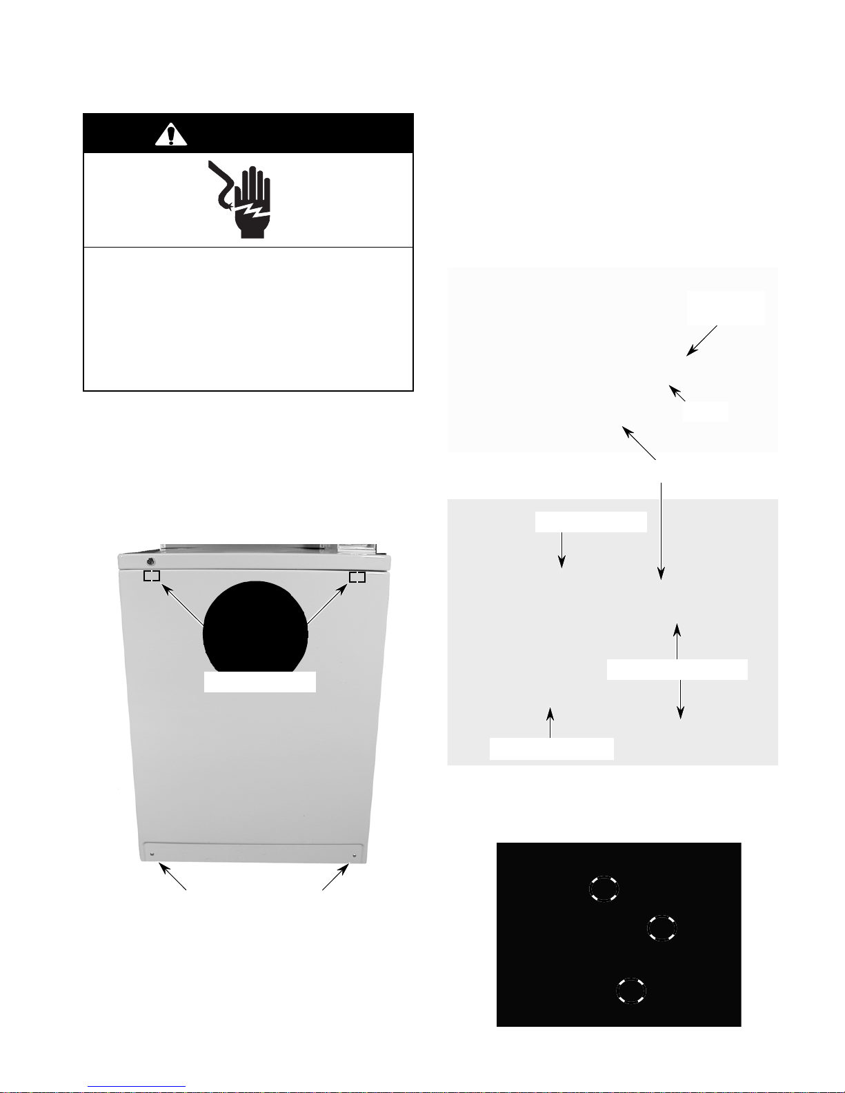
REMOVING THE PUMP, MOTOR START CAPACITOR, & MOTOR
4. To remove the pump:
WARNING
Electrical Shock Hazard
Disconnect power before servicing.
Replace all parts and panels before
operating.
Failure to do so can result in death or
electrical shock.
a) Release the two pump spring clips and
pull the pump away from the motor.
b) Place a container near the two pump
hoses to catch the water, then remove
the clamps from the inlet and outlet
hoses, and pull them off the pump.
Motor Start
Capacitor
1. Unplug washer or disconnect power.
2. Remove the two T-20 Torx screws from
the bottom of the front panel.
3. To remove the front panel, pull the bottom
forward to release it from the two top
retaining clips, and remove the panel.
Retaining Clips
Front Panel
Motor
Pump
Pump Inlet Hose
Release Spring Clips
Pump Outlet Hose
REASSEMBLY NOTE: Position the pump on
the motor shaft with the feet in the bracket
indents (circled below).
T-20 Torx Screws
NOTE: The pump, motor start capacitor, and
motor can more easily be accessed by tilting
the washer back, or by laying it on its rear
panel.
4-11
Continued on the next page.
Page 70
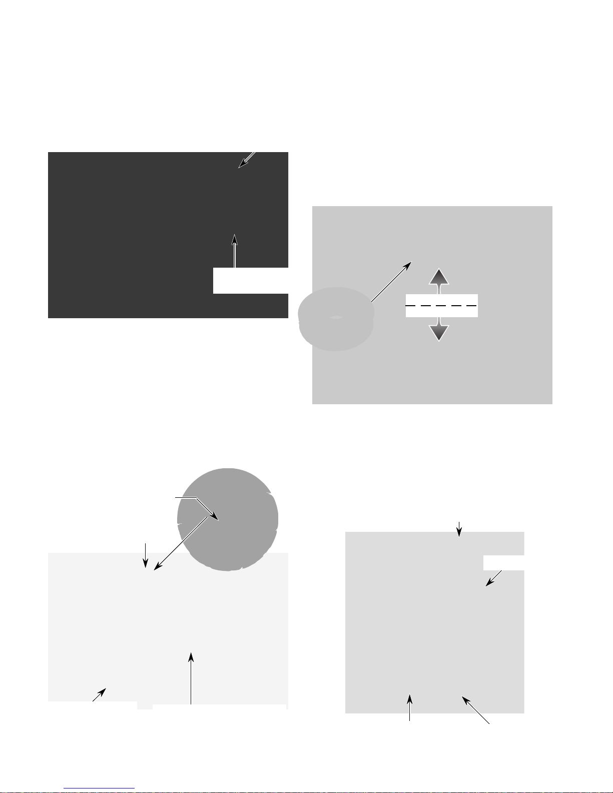
5. To remove the motor start capacitor:
a) Disconnect the two wires from the mo-
tor start capacitor terminals.
b) Loosen the hex-head screw on the
capacitor clamp and slide the capacitor out.
Clamp Screw
Motor Start
Capacitor Wires
6. To remove the motor:
e) Support the bottom of the motor with
one hand to keep it from dropping, then
pry the end of the top spring clip off the
motor with a screwdriver, (see the round
inset), and remove the lower spring
clip.
f) Lower the front of the motor until the
motor coupler pins disengage from the
motor coupler isolator, and remove the
motor.
Isolator
Motor Coupler
a) Remove the pump (see step 4 for the
procedure).
b) Raise the locking arm and disconnect
the wire connector from the motor.
c) Disconnect the two wires from the mo-
tor start capacitor terminals.
d) Remove the hex-head screw from each
of the two motor mounting spring clips.
Pry Off Spring Clip
Spring Clip Screw
Isolator
g) Remove the following components
from the motor:
• Motor Coupler
• Motor Start Capacitor & Clamp
• Rubber Motor Mounts (4)
• Cardboard Shield
Rubber Motor Mount
Motor Coupler
Spring Clip Screw
Motor Wire Connector Raise
Locking Arm To Release
4-12
Motor Start Capacitor & Clamp
Cardboard
Shield
Page 71
REMOVING THE AGITATOR & TRANSMISSION
WARNING
Electrical Shock Hazard
Disconnect power before servicing.
Replace all parts and panels before
operating.
Failure to do so can result in death or
electrical shock.
1. Unplug washer or disconnect power.
2. To remove the agitator:
a) Unsnap the agitator cap from the agi-
tator and remove it.
3. To remove the transmission:
a) Tape the washer lid closed.
b) Tilt the washer back at a 45° angle, or
lay it on its back panel.
c) Unclip the two spring clips from the
pump and remove the pump from the
motor shaft (see step 4 on page 4-11).
d) Disconnect the motor wire connector
and the two motor start capacitor wires
(see step 6 on page 4-12).
e) Disconnect the harness clip from the
transmission.
Pump
Spring Clip
(1 of 2)
Agitator Cap
b) Pull off the air dome cover and remove
the rubber O-ring from inside the agitator.
Air Dome Cover
Harness Clip
Transmission
Continued on the next page.
c) Remove the bolt from the agitator and
lift the agitator out of the washer.
4-13
Page 72
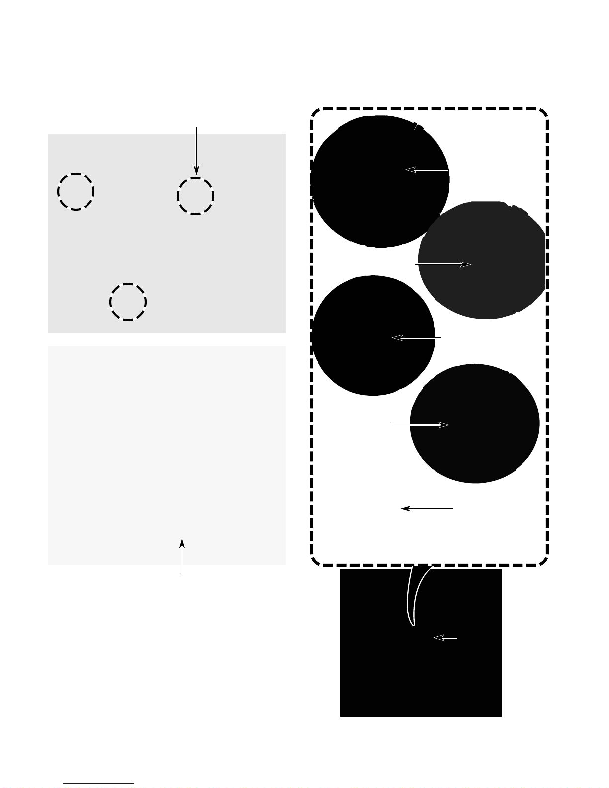
f) Remove the three 1/2″ bolts from the
transmission and pull the transmission
and motor assembly away from the
washer.
Bolt (1 of 3)
j) Slide the clutch off the agitator shaft.
k) Slide the anti-rattle clip off the agitator
shaft.
Thrust Washer
Spring Retaining Clip
Clutch Retaining Ring
Pull Transmission & Motor From Washer
Refer to the photos in the next column.
g) Remove the thrust washer from the
agitator shaft.
h) Use a screwdriver and unsnap the
spring retaining clip from the agitator
shaft.
i) Use a screwdriver and unsnap the
clutch retaining ring from the agitator
shaft.
Remove Clutch
Anti-Rattle Clip
Clutch Assembly
4-14
Page 73
l) Use a pair of pliers and remove the pad
assembly from the clutch drum.
n) Inspect the inside contact surface of
the drum for scratch marks, or uneven
wear. Inspect the clutch pad assembly
for loose, or worn pads (see the inset
photo to the left). If the distance between the clutch pad contact surface
and the clutch pad rivet head is less
than 1/10″, replace the clutch assembly
with part #285785.
o) Remove the motor from the transmis-
sion (see step 6 on page 4-12 for the
procedure).
p) Remove the two 1/2″ hex-head bolts
from the motor plate and remove the
plate.
Clutch Pad Assembly
Less Than 1/10″
Replace Clutch Pad Assembly
Drum
m) Clean the inner surface of the clutch
drum and the clutch pad assembly
surfaces with an approved solvent,
such as brake cleaner. Both assemblies must be free of dirt, oil, and grease
so that the proper spin speed and
water extraction may be achieved.
Motor
Plate
1/2″ Hex-Head Bolts
NOTE: For an exploded parts view of the
transmission, refer to section 8.
4-15
Page 74
REMOVING THE CABINET ASSEMBLY
WARNING
Electrical Shock Hazard
Disconnect power before servicing.
Replace all parts and panels before
operating.
Failure to do so can result in death or
electrical shock.
4. Use a screwdriver and unsnap the two
cabinet spring clips from the cabinet top.
5. Use a screwdriver and unsnap the two
cabinet side straps from the back of the
washer.
Cabinet Side
Strap (1 of 2)
1. Unplug washer or disconnect power.
2. Position the console to its service position
(see page 4-2 for the procedure).
3. With the full console model, disconnect
the main harness from the hidden lid switch
connector.
Clip
Lid Switch Connector
Clip
6. Remove the cabinet front panel (see page
4-11 for the procedure).
7. Remove the three bottom 5/16″ side panel
hex-head screws (2 on right, 1 on left).
5/16″ Hex-Head Screws
8. With the metercase model, disconnect
all metercase electrical connections, and
pull them into the console before removing the cabinet.
Spring
Clip
Pull Wire Harness Out Of Metercase
4-16
Page 75
9. Lift the cabinet slightly and tip it forward on
its front edges. IMPORTANT: The cabinet
will not stand on its own in the upright
position.
Plastic Lock
Damaged Bottom
Cabinet Flange
Properly Aligned
Bottom Cabinet Flange
NOTE: You can remove the right and left side
panels of the cabinet, instead of removing the
complete cabinet assembly. However, you will
have to remove the front panel first.
REASSEMBLY NOTE: When you reinstall the
cabinet, make sure that the small alignment
tabs at the front and rear of each side rail are
fully upright, as shown below, and not bent
over. Also make sure that the side rails are
straight and not deformed, otherwise, the cabinet will not fit properly.
Side Rail
Alignment Tab
NOTE: Tension can be added to the cabinet
clips to insure better frame-to-cabinet fit by
adjusting the clips. Apply pressure in the direction of the arrow while holding the clip in the
pliers. Another method is to install kit #488495.
4-17
Page 76
REMOVING THE TUB RING, BASKET,
OUTER TUB, AND BASKET DRIVE ASSEMBLY
TUB RING REASSEMBLY NOTE: When you
WARNING
reinstall the tub ring, snap the tub ring clip with
the narrow opening onto the catch on the outer
tub first, then work around the ring to snap the
remaining clips in place.
5. To remove the basket:
Electrical Shock Hazard
Disconnect power before servicing.
Replace all parts and panels before
operating.
Failure to do so can result in death or
electrical shock.
1. Unplug washer or disconnect power.
2. Remove the cabinet assembly (see page
4-16 for the procedure).
3. Remove the agitator (see step 2 on page
4-13 for the procedure).
4. To remove the tub ring from the outer
tub:
a) Press down on the tub ring at each of
the clips and pull the clips away from
the outer tub catches.
b) Lift the tub ring off the basket.
Press Down
a) Use a spanner wrench and remove the
spanner nut from the drive block. Tap
the spanner wrench with a hammer to
loosen the nut while holding the basket.
Spanner Wrench
Spanner Nut
b) Press down on one side of the basket
with the heels of both hands and release the basket from the drive block,
then lift the basket off the drive shaft,
and out of the outer tub.
Pull Out On Tub Ring Clip
Basket
Outer Tub
4-18
Page 77
c) Tap the bottom of the drive block with
a hammer and remove it from the basket drive shaft.
6. To remove the outer tub:
a) Remove the end of the counterbal-
ance spring from the hole in the frame.
NOTE: The end of the spring is connected to the base assembly. The
washer in the photo below is shown
laying on its rear panel.
Drive Block
DRIVE BLOCK REASSEMBLY NOTE: When
you reinstall the drive block on the basket drive,
make sure that you align the two slots in the
drive block with the corresponding tabs on the
top of the basket drive shaft. If they are misaligned, the basket drive and drive block will fail.
Tabs On Basket Drive
Slots In Drive Block
Drain Hose
Base Assembly
(Viewed From Bottom Of Unit)
Counterbalance Spring
b) Disconnect the end of the water level
hose from the side of the outer tub.
Tabs Flush
With Top
Surface
Of Drive
Block
Water Level Hose
Air Dome
Continued on the next page.
4-19
Page 78
c) Remove the end of the tub-to-pump
hose from the bottom of the outer tub.
d) Remove the hex-head screw from each
of the outer tub spring brackets.
Tub-To-Pump Hose
Tub Spring Bracket
& Screw
e) Turn the outer tub while you lift it off the
support assembly.
7. To remove the basket drive assembly:
a) Remove the tub ring and the basket
(see steps 4 and 5 on page 4-18 for the
procedures).
b) Remove the agitator and the transmis-
sion (see page 4-13 for the procedures).
c) Turn the clutch engagement cam on the
basket drive counterclockwise while pulling it toward you, and remove the basket drive from the support assembly.
Clutch Engagement Cam
OUTER TUB REASSEMBLY NOTE: When
you reinstall the outer tub, install the rear tub
spring bracket first.
NOTE: For spin tube bearing placement, refer
to the exploded parts view in Section 8.
4-20
Page 79
REMOVING THE SUSPENSION SYSTEM & BASE ASSEMBLY
WARNING
Pry Off
Suspension Pads
Electrical Shock Hazard
Disconnect power before servicing.
Replace all parts and panels before
operating.
Failure to do so can result in death or
electrical shock.
1. Unplug washer or disconnect power.
2. To remove the skate plate and suspen-
sion pads:
a) Remove the tub ring, basket, and outer
tub (see steps 4 through 6 on pages
4-18 through 4-20 for the procedures).
b) Lift the skate plate off the base assembly.
Skate Plate
3. To remove the base assembly:
a) Remove the tub ring, basket, outer tub,
and basket drive assembly (see steps
4 through 7 on pages 4-18 through 4-20
for the procedures).
b) Remove the skate plate (see step 2b).
c) Remove two 5/16″ hex-head base as-
sembly screws from the rear panel.
d) Remove the rear panel from the base
assembly.
e) If you are replacing the base assem-
bly, remove the feet, springs, etc. from
the assembly. NOTE: The new base
assembly is supplied with suspension
pads already installed.
Suspension Pads
Rear Panel Screw (1 of 2)
(Shown With Lower Surface Facing Up)
c) Pry the three suspension pads off the
top of the base assembly and replace
them (see the photo at the top of the
next column).
Base Assembly
4-21
Page 80
REMOVING THE VACUUM BREAK
WARNING
Electrical Shock Hazard
Disconnect power before servicing.
Replace all parts and panels before
operating.
Failure to do so can result in death or
electrical shock.
3. Push outward on the lower part of the two
vacuum break mounting tabs, lift out at the
bottom, and remove the vacuum break
from the slots in the rear panel.
Lift From Slots
1. Unplug washer or disconnect power.
2. Remove the cabinet assembly from the
washer (see page 4-16 for the procedure).
Vacuum Break
(View Of Rear Panel With Basket Removed)
Vacuum Break
4. Disconnect the water fill hose from the
vacuum break.
NOTE: Use a container to catch the water
from the hose.
Water Fill Hose
Vacuum Break
4-22
Page 81
REMOVING THE DUAL WATER VALVE, WATER LEVEL
SWITCH, AND DRAIN HOSE ASSEMBLY
3. To remove the dual water valve:
WARNING
Electrical Shock Hazard
Disconnect power before servicing.
Replace all parts and panels before
operating.
Failure to do so can result in death or
electrical shock.
1. Unplug washer or disconnect power.
2. Position the washer so that you can access the rear panel.
a) Remove the 5/16″ hex-head mounting
plate screw and the 1/4″ dual water
valve hex-head screw from the mounting plate.
b) Lift the mounting plate and remove it
from the rear panel.
c) Lift the dual water valve and unhook it
from the hole in the mounting plate.
5/16 ″
Screw
1/4 ″ Screw
Water
Level
Switch
Drain
Hose
Assembly
(View Of Rear Panel)
Dual
Water
Valve
d) Pull the dual water valve out of the rear
panel opening and disconnect the two
wire connectors from the terminals.
NOTE: Be sure to reinstall the red and
white connectors as shown below.
e) Remove the clamp from the end of the
hose and drain the water into a container.
W BR/R Y/R (2)W
Hose &
Clamp
4-23
Dual Water Valve
Continued on the next page.
Page 82
4. To remove the water level switch:
5. To remove the drain hose assembly:
a) Press the locking tab on the water level
switch, then rotate the switch in either
direction until the square extrusion
aligns with the cutout in the rear panel,
and remove the switch.
Turn 90°
Water Level Switch
Locking
Tab
b) Disconnect the air hose and wire connec-
tor from the switch.
a) Remove the 5/16″ hex-head screw from
the drain hose assembly.
b) Tilt the cabinet forward to lift the rear of
the unit.
c) Reach under the unit and gently pull
down on the drain hose assembly locking tab, and push the assembly out
through the rear panel.
5/16 ″
Screw
Drain Hose
Assembly
Locking
Tab
Air Hose
Tab
d) Pull the drain hose off the drain hose
assembly.
Wire
Connector
Dran Hose
Assembly
Drain Hose
4-24
Page 83
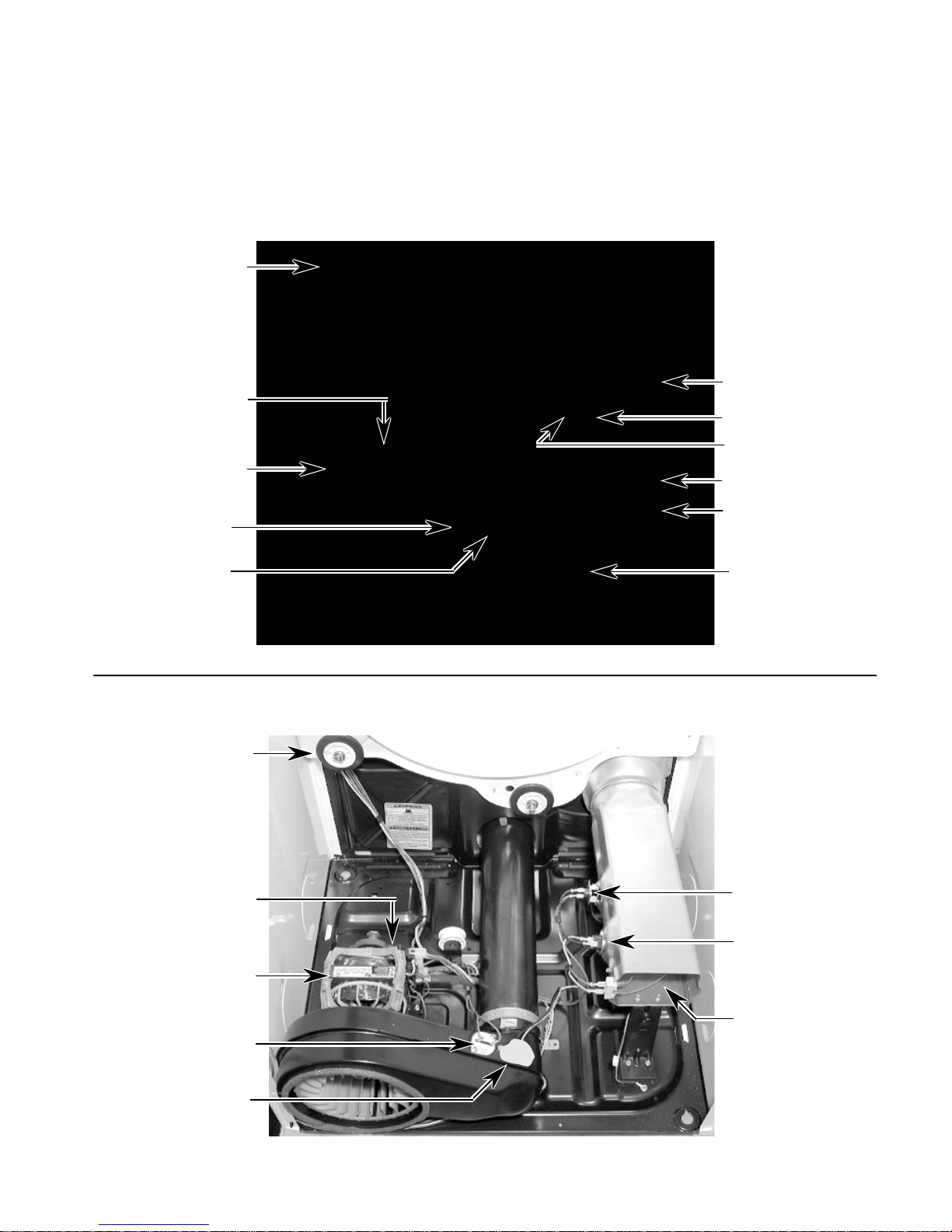
DRYERS
This section instructs the technician on how to service each component inside the ADVANTECH
Commercial Dryer. The gas and electric dryer components and their locations are shown below.
GAS DRYER COMPONENT LOCATIONS
Drum Roller (1 of 4)
Broken Belt Switch
(Mounted On Motor
Bracket)
Drive Motor
Thermal Fuse
Operating
Thermostat
High-Limit
Thermostat
Ignitor
Flame Sensor
Coil Assembly
Gas Valve
Spark Quencher
NOT SHOWN:
Door Switch
Control & Display
Boards
ELECTRIC DRYER COMPONENT LOCATIONS
Drum Roller (1 of 4)
Broken Belt Switch
(Mounted On Motor
Bracket)
Drive Motor
Thermal Fuse
Operating
Thermostat
Thermal Cutoff
High-Limit
Thermostat
Heater Coil
NOT SHOWN:
Door Switch
Control & Display
Boards
4-25
Page 84
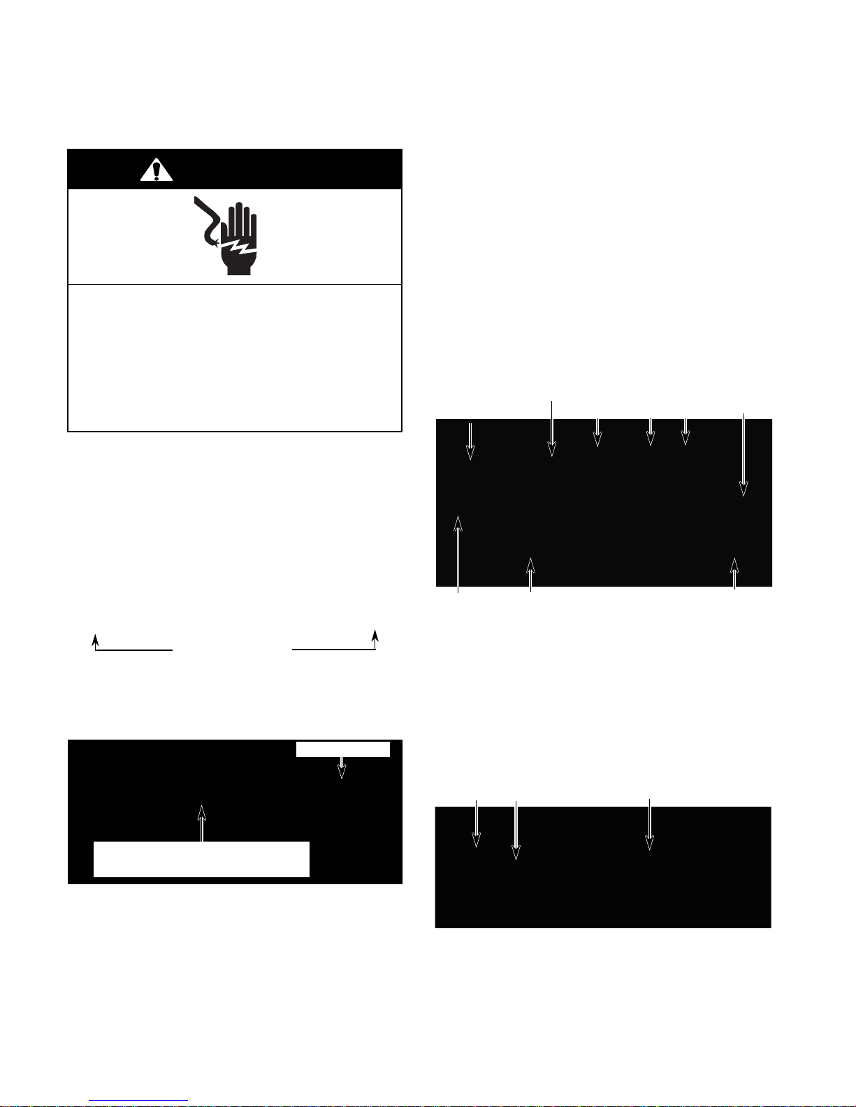
Freestanding Dryers
REMOVING THE CONSOLE COMPONENTS
WARNING
Electrical Shock Hazard
Disconnect power before servicing.
Replace all parts and panels before
operating.
Failure to do so can result in death or
electrical shock.
1. Unplug dryer or disconnect power.
2. Turn off gas supply to dryer.
5. To remove the ADVANTECH control
board:
a) Disconnect the board connectors at
P1, P4, P8, and P11.
b) Disconnect the four wires at the dryer
motor relay K1 (RD & RD), and dryer
heater relay K2 (BU & BK).
c) Disconnect the green ground wire from
terminal P6.
d) Remove the six 5/16″ hex-head screws
from the board and remove the board.
ADVANTECH Control Board
Screw (1 of 6)
P4
Relays
K2
K1
P1
3. Remove the two T-15 Torx screws from
the console.
T-15 Torx Screws
4. Slide the console to the front of the unit
slightly, then rotate it back and place it in
the “service” position.
Card Reader
Control Board And Display Board
(Below Control Board)
P11
P8
Ground Wire
6. To remove the display board:
a) Remove the ADVANTECH
board (see step 5).
b) Disconnect the connector from the dis-
play board at P1.
c) Unlatch the display board from the
holder and remove it.
P1
Latch
Display Board
control
4-26
Page 85

7. To remove the membrane switch:
a) From the rear of the unit, remove the
screw from either of the end caps.
Rear Screw
e) Bend the tabs on the membrane switch
and remove them from the slots in the
board. NOTE: Be sure to install the new
membrane switch on the board with the
ribbon cable facing the end with the two
alignment pins that are on the opposite
side of the board. Also make sure that
the ends of the two alignment pins are
in their bracket holes.
Hinge
End Cap
b) Remove the ADVANTECH control and
display boards (see steps 5 and 6).
c) Remove the two ground screws from
the green ground wires.
NOTE: The membrane switch board will be
loose when you remove the bracket screws in
the next step. Be careful not to drop the board
when you remove the bracket.
d) Remove the two end cap screws from
both ends of the console bracket. Carefully lift the bracket from the console,
and remove the loose end cap and the
membrane switch board.
Alignment Pin
Ribbon Cable
Backer Board
Membrane Switch
Alignment Pin
Membrane Switch Tabs
Continued on the next page.
Ground Screws
End Cap Screws
4-27
Page 86
8. To remove the card reader assembly
on a full console machine:
a) Disconnect the connector from the
ADVANTECH
ADVANTECH Control Board
P11
control board at P11.
Card Reader
b) Remove the two screws from the card
reader assembly and remove the assembly.
Card Reader Screws
b) Remove the two hex-head screws from
the console support bracket, and slide
the end cap off the end of the panel.
Console Support
Bracket Screws
c) If a mounting stud is not installed on the
new end cap, remove the stud from the
old cap, and install it on the new one.
Card Reader Assembly
9. To remove an end cap from the console:
a) Remove the hex-head screw from the
rear of the end cap.
Rear Screw
Left End
Cap
Left End
Cap
Mounting Stud
4-28
Page 87
REMOVING THE MONEY ACCEPTORS & METERCASE
4. To remove the coinslide assembly:
WARNING
a) Using a 5/16″ socket, unscrew the re-
taining bolt from the money acceptor,
and remove the bolt from inside the
metercase.
Electrical Shock Hazard
Disconnect power before servicing.
Replace all parts and panels before
operating.
Failure to do so can result in death or
electrical shock.
1. Unplug dryer or disconnect power.
2. Turn off gas supply to dryer.
3. Unlock the service access door and remove it from the top of the metercase.
Access Door
Coinslide
Switch (inside)
On Coinslide
Extension
Metercase
Coinslide
Assembly
Coinbox
5/16″ Retaining Bolt
b) Remove the 5/16″ hex-head screw from
the coinslide green ground wire that is
attached inside the metercase.
Ground Wire
Continued on the next page.
4-29
Page 88

c) Lift the coinslide to release it from the
holes in the metercase, and pull it forward out of the metercase.
d) Unplug the two wires from the coinslide
switch.
Coinslide Switch
With 2 Wires
5. To remove the card reader assembly:
a) Using a 5/16″ socket, unscrew the re-
taining bolt from the money acceptor,
and remove the bolt from inside the
metercase.
b) Lift and pull the card reader assembly
forward and remove it from the
metercase.
Metercase
Card Reader
Assembly
c) Position the console to its service posi-
tion (see page 4-26 for the procedure).
d) If you are changing to a different type of
money acceptor, disconnect the connector from P11 on the ADVANTECH
control board, and remove the card
reader wire harness.
P11
ADVANTECH Control Board
5/16″ Retaining Bolt
e) If you are replacing a defective card
reader, disconnect the wire connector
from the card reader assembly.
4-30
Page 89
6. To remove the coindrop assembly:
7. To remove the coinbox switch:
a) From inside the open access panel of
the metercase, remove the screws or
hex-bolts from the back of the coindrop
assembly.
b) Position the console to its service posi-
tion (see page 4-26 for the procedure).
c) Disconnect the connector(s) at P10 /
COIN 1 (& P12 / COIN 2) on the
ADVANTECH
P10 (COIN 1)
P12 (COIN 2)
control board.
ADVANTECH Control Board
d) Remove the coindrop with its wire har-
ness from the unit.
a) Unlock and remove the service access
panel and the coinbox from the metercase.
b) Disconnect the two wires from the
coinbox switch terminals from inside
the metercase.
c) Squeeze the locking tabs on the top
and bottom of the switch body and push
the switch into the coinbox compartment of the metercase.
Coindrop
Assembly
Top Locking Tab
Coinbox Switch Wires
Continued on the next page.
4-31
Page 90
8. To remove the service switch:
a) Push up on the switch body, and re-
move the switch from the retaining
bracket from inside the metercase.
b) Disconnect the two wires from the ser-
vice switch terminals.
Retaining Bracket
Service Switch Wires
9. To remove the metercase:
c) Remove the 1/2″ hex-head screws from
the front and rear of the metercase,
then lift the metercase off the dryer, and
remove it.
Coin Funnel
1/2″ Hex-Head Front
Metercase Screws
a) Remove the money acceptor from the
metercase.
Coinslide Switch
With 2 Wires
b) Unlock and remove the coinbox.
NOTE: Prior to removal of the metercase assembly, pull all of the harness wires back into
the console area.
10. To remove the adapter plate:
a) Remove the coinbox.
b) Unlock and remove the service access
door.
c) Using a ratchet with a 10″ extension
and a 3/8″ socket, remove the two hexnuts from the adapter plate through the
service access opening.
d) Remove the 3/8″ hex-nut from the top
of the coinbox opening. Pull from the
top, and remove the adapter plate.
Hex-Nuts (Behind
Adapter Plate)
Adapter Plate
Coinbox Area
Hex-Nut
4-32
Page 91
REMOVING THE CABINET
WARNING
4. To remove the lower service access
panel, use a putty knife, and pry down on
the upper retaining clips while pulling forward on the lower service access panel,
and remove the panel.
Electrical Shock Hazard
Disconnect power before servicing.
Replace all parts and panels before
operating.
Failure to do so can result in death or
electrical shock.
1. Unplug dryer or disconnect power.
2. Turn off gas supply to dryer.
3. To remove the dryer top:
a) Slide the console to the front of the unit
slightly, then rotate it back and place it
in the service position.
b) Remove the three rear hex-head screws
from the top.
Clip
Lower Service
Access Panel
Pry
Down
Clip
5. To remove the front panel:
a) Remove the lower service access panel
(see step 4).
b) Remove the two bottom hex-head
screws and the two T-15 Torx screws
and flat washers from the top of the
front panel.
Front Panel
3 Screws
c) Slide the top forward to release if from
the two front side panel clips, and remove the top from the unit.
Side
Panel
Clips
Torx Screws W/Flat Washers
Hex-Screws
Continued on the next page.
4-33
Page 92

c) Pull the top of the front panel forward
just enough to access the door switch
wires, then remove the two wires from
the switch terminals.
Door Switch Wires
Door Switch
d) Lower the front panel to disengage the
two front drum rollers from the drum,
and remove the front panel.
Front Rollers
4-34
Page 93
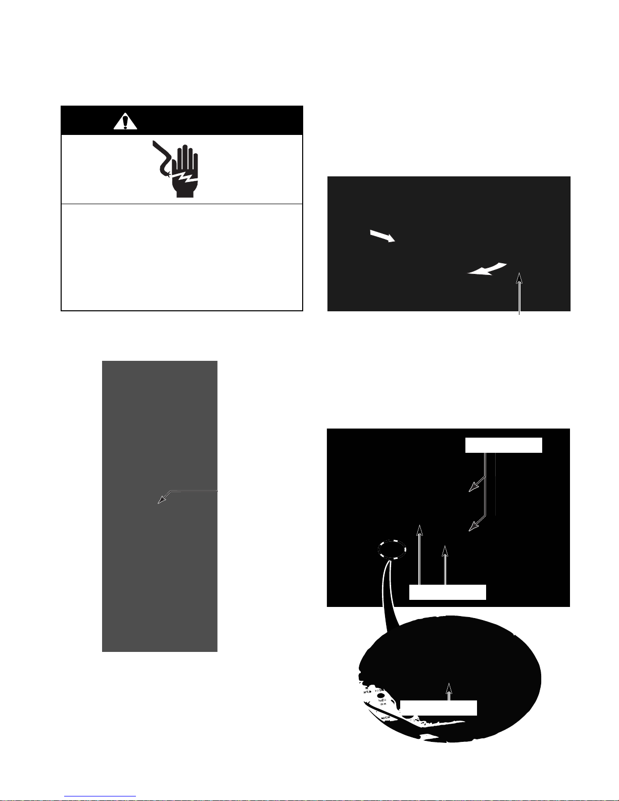
Stack Dryers
REMOVING THE CONSOLE COMPONENTS
WARNING
Electrical Shock Hazard
Disconnect power before servicing.
Replace all parts and panels before
operating.
Failure to do so can result in death or
electrical shock.
3. To remove the console:
a) Unlock the console, pull the right side
out, and remove the console from the
unit so you can access the wiring.
1. Unplug dryers or disconnect power.
2. Turn off gas supply to dryers.
Console
Console Lock
b) Disconnect the two P1 connectors for
the upper and lower dryers from the
display boards.
c) Remove the 5/16″ hex-head screw from
the console securing the red retaining
wire and green ground wire.
P1 Connectors
Display Boards
4-35
Ground Screw
Continued on the next page.
Page 94
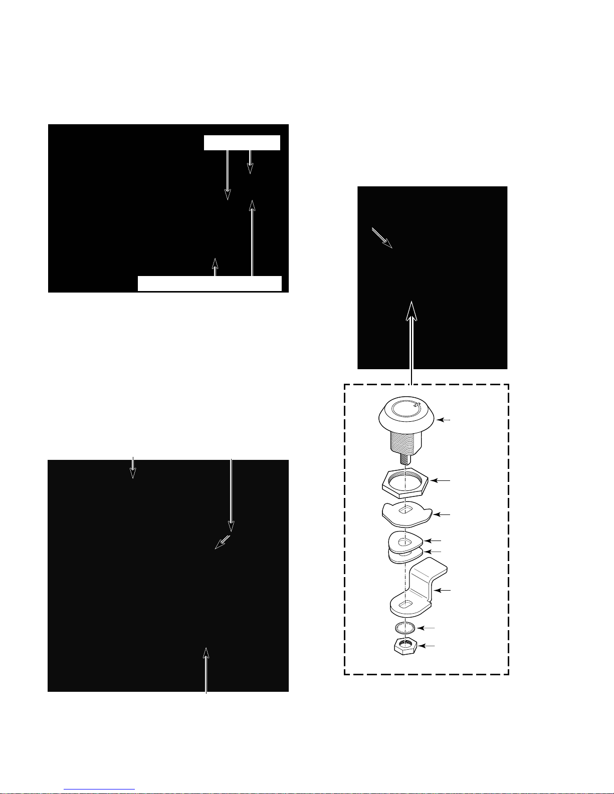
d) Disconnect the two P4 connectors for
Lock
7/8″ Hex-Nut
Lock Stop
Locking Cam
Wave W ashers 2
7/16″ Hex-Nut
Lockwasher
the upper and lower dryers from the
ADVANTECH
control boards and re-
move the console from the unit.
P4 Connectors
ADVANTECH Control Boards
4. To remove the cycle selector switches
from the console:
a) Remove the console (see step 3).
b) Disconnect the selector switch wires.
NOTE: A switch wiring color-code
sticker is shown on the bracket.
c) Remove the four bracket screws and lift
the bracket and selector switches from
the console.
5. To remove the lock from the console:
a) Remove the console (see step 3).
b) Remove the 7/16″ hex-nut from the
lock and remove the lockwasher, locking cam, 2 wave washers, and lock stop
(see the illustration below).
c) Remove the 7/8″ hex-nut from the lock
and remove the lock from the console.
Console Lock
Upper Dryer Selector Switch
Lower Dryer Selector Switch
Bracket W/4 Screws
4-36
Page 95

6. To remove the display boards from the
console:
a) Remove the console (see step 3).
b) Remove the 11/32″ hex-nuts from the
upper and lower display boards and
remove the boards from the console.
11/32″ Nuts
Upper Display
Lower Display
4-37
Page 96
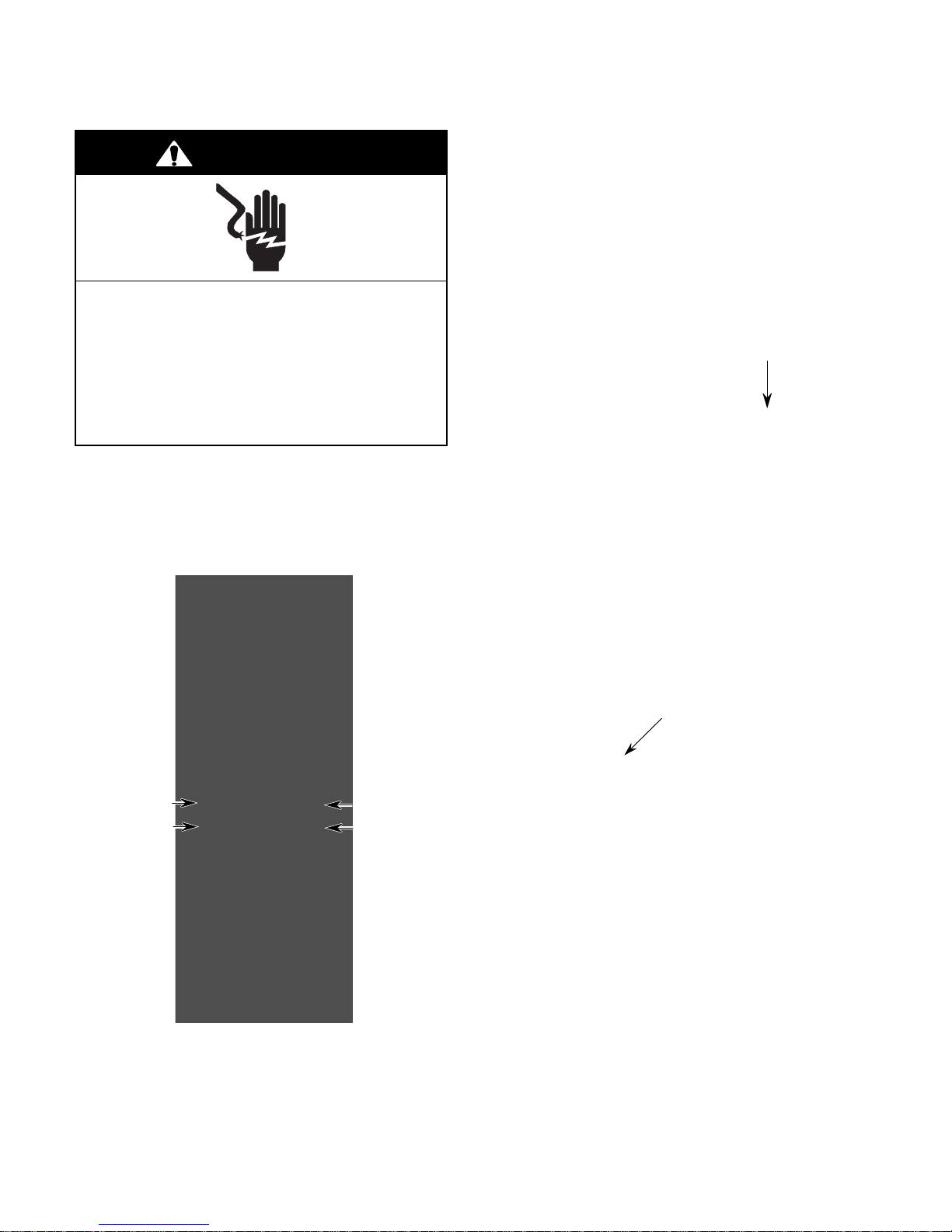
REMOVING THE MONEY ACCEPTORS
WARNING
Electrical Shock Hazard
Disconnect power before servicing.
Replace all parts and panels before
operating.
Failure to do so can result in death or
electrical shock.
1. Unplug dryers or disconnect power.
2. Turn off gas supply to dryers.
3. Remove the console (see step 3 on page
4-35 for the procedure).
4. To remove the coinslide assembly:
a) Using a 5/16″ socket, unscrew the re-
taining bolt from the money acceptor,
and remove the bolt from inside the
console opening.
Coinslide Retaining Bolt
b) Lift the coinslide and pull it forward out
of the unit.
c) Unplug the two wires from the coinslide
switch.
d) Remove the ground wire screw from
the bottom of the coinslide assembly.
Coinslide
Coinbox
Example Of Various Money Acceptor Configurations
Coindrop
Coinbox
Coinslide Switch
With 2 Wires
4-38
Page 97
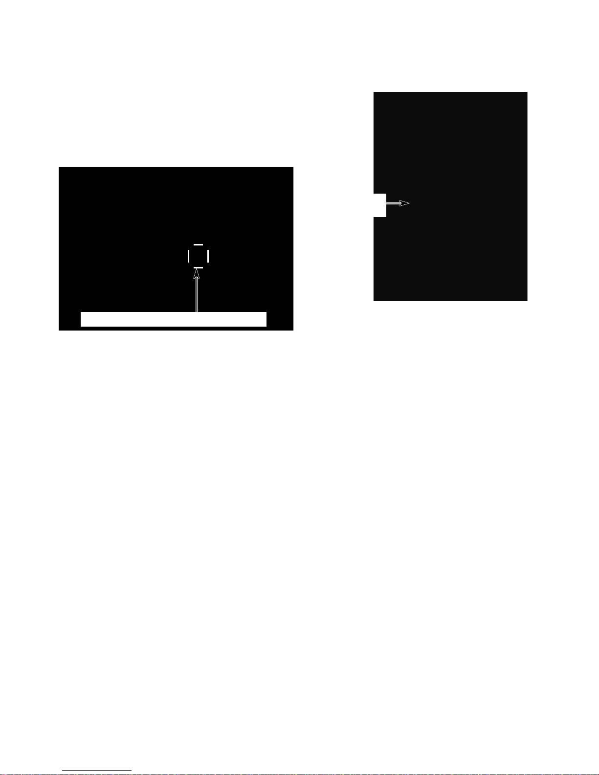
5. To remove the coindrop assembly:
a) From inside the console opening, re-
move the screws or hex-bolts from the
back of the coindrop assembly.
b) Disconnect the connector(s) at P10 /
COIN 1 (& P12 / COIN 2) on the upper
or lower ADVANTECH
ADVANTECH Control Board P10 & P12
control board.
c) Remove the coindrop with its wire har-
ness from the unit.
Coindrop
Assembly
4-39
Page 98
REMOVING THE ADVANTECH CONTROL BOARDS
WARNING
Electrical Shock Hazard
Disconnect power before servicing.
Replace all parts and panels before
operating.
Failure to do so can result in death or
electrical shock.
1. Unplug dryers or disconnect power.
2. Turn off gas supply to dryers.
3. Remove the console (see step 3 on page
4-35 for the procedure).
4. Disconnect the board connectors at P1,
P4, P8, and P11.
5. Disconnect the four wires at the dryer
motor relay K3 (RD & RD), and dryer
heater relay K2 (BU & BK).
6. Disconnect the green ground wire from
terminal P6.
7. Remove the six 5/16″ hex-head screws
from the board and remove the board.
ADVANTECH Control Board
Screw (1 of 6)
P4
Relays
K3
K2
P1
ADVANTECH Control Board—Upper Dryer
FRONT OF UNIT
ADVANTECH Control Board—Lower Dryer
(Viewed From Top With Upper Dryer Removed)
P11
P8
Ground Wire
4-40
Page 99
REMOVING THE UPPER DRYER
WARNING
Electrical Shock Hazard
6. Remove the upper dryer’s lower service
access panel.
Clip
Lower Service
Access Panel
Disconnect power before servicing.
Replace all parts and panels before
operating.
Failure to do so can result in death or
electrical shock.
1. Unplug dryers or disconnect power.
2. Turn off gas supply to dryers.
3. Remove the console (see step 3 on page
4-35 for the procedure).
4. Remove the money acceptors (see page
4-38 for the procedure).
5. Remove the cotter pins (if installed) from
the two front security bolts.
Pry
Down
Clip
7. Remove the two front security bolts and
flat washers from the upper dryer.
Front Security Bolts & Flat Washers
8. Disconnect the main harness connector
from the top of the collar.
Cotter Pin
Security Bolt
Main Harness Connector
Continued on the next page.
4-41
Page 100

CAUTION: Use two people to lift the upper
dryer when you remove it from its mounting
location.
9. Slide the upper dryer forward just far
enough to unhook the rear feet from the
collar. Using two people, lift the dryer off
the lower unit.
4-42
 Loading...