

Page 1
CONSUMER SERVICES TECHNICAL
EDUCATION GROUP PRESENTS
R-100
JOB AID
Part No. 8178485
10,000 BTU
PORTABLE
ROOM AIR
CONDITIONER
Model ACP102PR
Page 2

FORWARD
This Whirlpool Job Aid, “10,000 BTU Portable Room Air Conditioner” (Part No. 8178485), provides the technician with information on the installation, operation, and service of the 10,000
BTU Portable Room Air Conditioner. For specific information on the model being serviced, refer
to the “Use and Care Guide,” or “Tech Sheet” provided with the air conditioner.
The Wiring Diagram used in this Job Aid is typical and should be used for training purposes only.
Always use the Wiring Diagram supplied with the product when servicing the unit.
GOALS AND OBJECTIVES
The goal of this Job Aid is to provide information that will enable the service technician to properly diagnose malfunctions and repair the 10,000 BTU Portable Room Air Conditioner.
The objectives of this Job Aid are to:
Understand and follow proper safety precautions.
•
Successfully troubleshoot and diagnose malfunctions.
•
Successfully perform necessary repairs.
•
Successfully return the air conditioner to its proper operational status.
•
WHIRLPOOL CORPORATION assumes no responsibility for any repairs
made on our products by anyone other than Authorized Service Technicians.
Copyright © 2005, Whirlpool Corporation, Benton Harbor, MI 49022
- ii -
Page 3

TABLE OF CONTENTS
Page
GENERAL . . . . . . . . . . . . . . . . . . . . . . . . . . . . . . . . . . . . . . . . . . . . . . . . . . . . . . . . . . . . . . 1-1
Safety First . . . . . . . . . . . . . . . . . . . . . . . . . . . . . . . . . . . . . . . . . . . . . . . . . . . . . . . . . . . . 1-1
Whirlpool Model & Serial Number Designations
Model & Serial Number Label Location
Specifications . . . . . . . . . . . . . . . . . . . . . . . . . . . . . . . . . . . . . . . . . . . . . . . . . . . . . . . . . . 1-4
Whirlpool Air Conditioner Warranty . . . . . . . . . . . . . . . . . . . . . . . . . . . . . . . . . . . . . . . . . . 1-5
ALLATION INFORMATION . . . . . . . . . . . . . . . . . . . . . . . . . . . . . . . . . . . . . . . . . . . . . 2-1
INST
Installation Requirements . . . . . . . . . . . . . . . . . . . . . . . . . . . . . . . . . . . . . . . . . . . . . . . . . 2-1
Installation Instructions . . . . . . . . . . . . . . . . . . . . . . . . . . . . . . . . . . . . . . . . . . . . . . . . . . . 2-3
. . . . . . . . . . . . . . . . . . . . . . . . . . . . . . . . . . . . . . . 1-3
. . . . . . . . . . . . . . . . . . . . . . . . . . . . . . . . 1-2
PRODUCT OPERA
Theory Of Operation . . . . . . . . . . . . . . . . . . . . . . . . . . . . . . . . . . . . . . . . . . . . . . . . . . . . . 3-1
Portable
Portable
Troubleshooting . . . . . . . . . . . . . . . . . . . . . . . . . . . . . . . . . . . . . . . . . . . . . . . . . . . . . . . . 3-10
COMPONENT
Component Locations
Removing The Cabinet . . . . . . . . . . . . . . . . . . . . . . . . . . . . . . . . . . . . . . . . . . . . . . . . . . . 4-2
Removing
Removing
Removing
Removing
Removing
Removing
Wire
Removing
Removing
Removing
Removing
Removing
Removing
Removing
Air Conditioner Use . . . . . . . . . . . . . . . . . . . . . . . . . . . . . . . . . . . . . . . . . . . . . . . 3-3
Air Conditioner Care . . . . . . . . . . . . . . . . . . . . . . . . . . . . . . . . . . . . . . . . . . . . . . 3-9
The User Interface Board . . . . . . . . . . . . . . . . . . . . . . . . . . . . . . . . . . . . . . . . . 4-4
The Louver Motor & Receiver Board . . . . . . . . . . . . . . . . . . . . . . . . . . . . . . . . 4-5
The Control Board . . . . . . . . . . . . . . . . . . . . . . . . . . . . . . . . . . . . . . . . . . . . . . 4-6
A Fan Motor Capacitor, Compressor Motor Capacitor, & Transformer . . . . . . . 4-7
The Evaporator Fan Motor . . . . . . . . . . . . . . . . . . . . . . . . . . . . . . . . . . . . . . . . 4-9
The Room Temp And De-Ice Thermistors . . . . . . . . . . . . . . . . . . . . . . . . . . . .4-11
Tie Locations . . . . . . . . . . . . . . . . . . . . . . . . . . . . . . . . . . . . . . . . . . . . . . . . . . . . . . 4-13
The Water Pump Motor . . . . . . . . . . . . . . . . . . . . . . . . . . . . . . . . . . . . . . . . . 4-14
The High & Low Water Level Switches . . . . . . . . . . . . . . . . . . . . . . . . . . . . . 4-16
The Condenser Fan Motor . . . . . . . . . . . . . . . . . . . . . . . . . . . . . . . . . . . . . . . 4-18
The Overload Protector And The Compressor . . . . . . . . . . . . . . . . . . . . . . . . 4-20
The Evaporator . . . . . . . . . . . . . . . . . . . . . . . . . . . . . . . . . . . . . . . . . . . . . . . . 4-22
The Condenser . . . . . . . . . . . . . . . . . . . . . . . . . . . . . . . . . . . . . . . . . . . . . . . . 4-24
The Power Supply Cord . . . . . . . . . . . . . . . . . . . . . . . . . . . . . . . . . . . . . . . . . 4-26
TION . . . . . . . . . . . . . . . . . . . . . . . . . . . . . . . . . . . . . . . . . . . . . . . . . . . . 3-1
ACCESS
. . . . . . . . . . . . . . . . . . . . . . . . . . . . . . . . . . . . . . . . . . . . . . . . . . 4-1
. . . . . . . . . . . . . . . . . . . . . . . . . . . . . . . . . . . . . . . . . . . . . . . . . . . . 4-1
COMPONENT TESTING . . . . . . . . . . . . . . . . . . . . . . . . . . . . . . . . . . . . . . . . . . . . . . . . . . . 5-1
Louver Motor . . . . . . . . . . . . . . . . . . . . . . . . . . . . . . . . . . . . . . . . . . . . . . . . . . . . . . . . . . . 5-1
Fan Motor & Compressor Motor Capacitor . . . . . . . . . . . . . . . . . . . . . . . . . . . . . . . . . . . . 5-2
Transformer . . . . . . . . . . . . . . . . . . . . . . . . . . . . . . . . . . . . . . . . . . . . . . . . . . . . . . . . . . . . 5-2
Evaporator Fan Motor . . . . . . . . . . . . . . . . . . . . . . . . . . . . . . . . . . . . . . . . . . . . . . . . . . . 5-3
Condenser Fan Motor . . . . . . . . . . . . . . . . . . . . . . . . . . . . . . . . . . . . . . . . . . . . . . . . . . . . 5-3
Room
W
High
Overload Protector . . . . . . . . . . . . . . . . . . . . . . . . . . . . . . . . . . . . . . . . . . . . . . . . . . . . . . 5-5
Compressor . . . . . . . . . . . . . . . . . . . . . . . . . . . . . . . . . . . . . . . . . . . . . . . . . . . . . . . . . . . . 5-6
WIRING DIAGRAM . . . . . . . . . . . . . . . . . . . . . . . . . . . . . . . . . . . . . . . . . . . . . . . . . . . . . . . 6-1
Temp & De-Ice Thermistors . . . . . . . . . . . . . . . . . . . . . . . . . . . . . . . . . . . . . . . . . . 5-4
ater Pump Motor . . . . . . . . . . . . . . . . . . . . . . . . . . . . . . . . . . . . . . . . . . . . . . . . . . . . . . 5-4
And Low Water Level Switches . . . . . . . . . . . . . . . . . . . . . . . . . . . . . . . . . . . . . . . . . 5-5
- iii -
Page 4

— NOTES —
- iv -
Page 5
GENERAL
DANGER
WARNING
SAFETY FIRST
Your safety and the safety of others is very important.
We have provided many important safety messages in this Job Aid and on the appliance.
Always read and obey all safety messages.
This is the safety alert symbol.
This symbol alerts you to hazards that can kill or hurt you and others.
All safety messages will follow the safety alert symbol and either the word
“DANGER” or “WARNING.” These words mean:
You can be killed or seriously injured if you don’t
immediately follow instructions.
ou can be killed or seriously injured if you don’t
Y
follow instructions.
All safety messages will tell you what the potential hazard is, tell you how to reduce the chance
of injury, and tell you what can happen if the instructions are not followed.
1-1
Page 6

WHIRLPOOL MODEL & SERIAL NUMBER DESIGNATIONS
MODEL NUMBER
MODEL NUMBER AC P 10 2 P R 0
AC = North America
MAC = Mexico
YAC = Canada
MODEL TYPE
D = Value model
E = Heat & cool
M = Value model
P = Portable
Q = Designer
S = Sliding Window
U = Thru The Wall
BTU CAPACITY
05 to 24, ie 10 = 10,000 BTU
ELECTRICAL CODE
2 = 115 Volt Standard
4 = 230 Volt Standard
8 = 115 Volt Energy Star
9 = 230 Volt Energy Star
MANUFACTURING LOCATION
P = Purchased
YEAR OF INTRODUCTION
R = 2005
ENGINEERING CHANGE 0,1,2, ETC.
SERIAL NUMBER
SERIAL NUMBER QK S 08 08012
MANUFACTURING RESPONSIBILITY
QK = LaV
YEAR OF PRODUCTION
S = 2005
WEEK OF PRODUCTION
8th WEEK
PRODUCT SEQUENCE NUMBER
ergne, TN
1-2
Page 7
MODEL & SERIAL NUMBER LABEL LOCATION
The Model/Serial Number label location is shown below.
Model/Serial Number
Label Location
1-3
Page 8

SPECIFICATIONS
Operation Type
Cooling
Dimensions
Indoor Unit
Height = 32-1/4ʺ (820 mm)
Width = 17-3/4ʺ (450 mm)
Depth = 16ʺ (405 mm)
eight (Net)
W
Indoor Unit = 81.6 lbs. (37.0 kg)
Electrical
Voltage = 115 VAC
Frequency = 60 Hz
Refrigerant
Type: R22
Quantity: 23.3 oz.
Cooling Capacity
10,000 BTU/h
Working Temperature Range
Indoor = 64.4 / 90°F (18.0 / 32.0°C)
1-4
Page 9

WHIRLPOOL AIR CONDITIONER WARRANTY
FIVE YEAR FULL WARRANTY
For five years from the date of purchase, when this air conditioner (excluding air filter) is installed, operated and maintained according to instructions attached to or furnished with the product, we at Whirlpool
Corporation or Whirlpool Canada LP will repair or replace the product at our discretion to correct defects
in materials or workmanship in the mechanical or electrical controls and in the sealed refrigeration system,
including the compressor, evaporator, condenser, dry-strainer and connection tubing. Service must be
provided by a Whirlpool designated service company.
30 DAY LIMITED WARRANTY ON AIR FILTER
For 30 days from date of purchase, when this air conditioner is operated and maintained according to
instructions attached to or furnished with the product, Whirlpool Corporation or Whirlpool Canada LP will
pay for replacement air filter to correct defects in materials or workmanship.
Whirlpool Corporation or Whirlpool Canada LP will not pay for:
1. Service calls to correct the installation of your air conditioner, instruct you on how to use your air
conditioner, to replace house fuses or correct house wiring or reset circuit breakers, or to clean or
replace owner accessible air filters.
2. Repairs when your air conditioner is used in other than normal, single-family household use.
3. Damage resulting from accident, alteration, misuse, abuse, fire, floods, acts of God, improper instal-
lation
not in accordance with local electrical and plumbing codes, or use of products not approved
by Whirlpool Corporation or Whirlpool Canada LP.
4. Replacement parts or repair labor costs for units operated outside the United States or Canada.
5. Pickup and delivery. Your air conditioner is designed to be repaired in the home.
6. The removal and reinstallation of your air conditioner if it is installed in an overhead or other inacces-
sible location or is not installed in accordance with published installation instructions.
7.
Repairs to parts or systems resulting from unauthorized modifications made to the appliance.
8. In Canada, travel or transportation expenses for customers who reside in remote areas.
WHIRLPOOL CORPORATION AND WHIRLPOOL CANADA LP SHALL
NOT BE LIABLE FOR INCIDENTAL OR CONSEQUENTIAL DAMAGES.
Some states and provinces do not allow the exclusion or limitation of incidental or consequential damages,
so this exclusion or limitation may not apply to you. This warranty gives you specific legal rights and you
may also have other rights which vary from state to state and province to province.
Outside
Whirlpool dealer to determine if another warranty applies.
If
you need service, first see “Troubleshooting” in the Use & Care Guide. Additional help can be found by
checking “Assistance or Service,” or by calling our Customer eXperience Center at 1-800-253-1301,
anywhere in the U.S.A. or write: Whirlpool Corporation, Customer eXperience Center, 553 Benson Road,
Benton Harbor, MI 49022-2692.
For service in Canada, call 1-800-807-6777.
trained to fulfill the product warranty and provide after-warranty service, anywhere in Canada. If you need
further assistance, you can write to Whirlpool Canada LP with any questions or concerns at: Customer
Interaction Center, Whirlpool Canada LP, 1901 Minnesota Court, Mississauga, Ontario L5N 3A7. Please
include a daytime phone number in your correspondence.
the 50 United States and Canada, this warranty does not apply. Contact your authorized
from
Whirlpool Canada LP designated service technicians are
1-5
Page 10

— NOTES —
1-6
Page 11
INSTALLATION INFORMATION
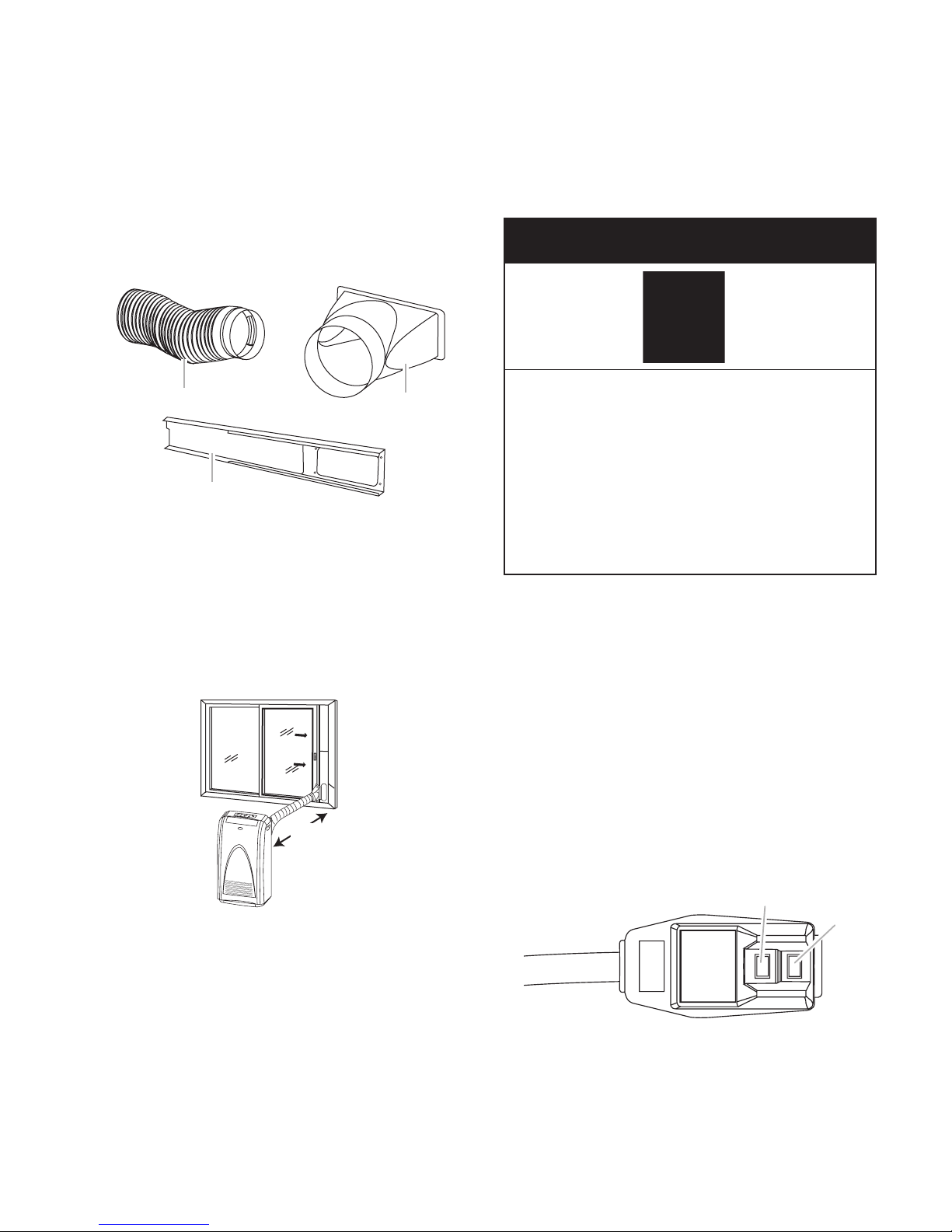
A. Flexible exhaust hose
B. Window exhaust adapter
C. Window slider kit (3)
A
B
C
191/2" - 705/8"
(49.5 - 180 cm)
A. Reset button
B. Test button
TEST
RESET
A
B
INSTALLATION REQUIREMENTS
PARTS
Parts supplied
Check that all parts are included in parts package.
LOCATION REQUIREMENTS
NOTES:
Locate the air conditioner between 19-1/2"
•
(49.5 cm) and 70-5/8" (180 cm) from window or door
.
ELECTRICAL REQUIREMENTS
Electrical Shock Hazard
Plug into a grounded 3 prong outlet.
Do not remove ground prong.
Do not use an adapter.
Do not use an extension cord.
Failure to follow these instructions can
result in death, fire, or electrical shock.
The portable air conditioner should be con-
•
nected to a 115 V, 60 Hz, 15- or 20-amp
fused 3 prong grounded outlet.
use of a time-delay fuse or time-delay
The
•
circuit breaker is recommended.
•
Keep
the required distance from the return
air outlet to the wall or other obstacles at
least 19-1/2" (49.5 cm).
•
Do not block air outlet.
•
Provide
easy access to grounded 3 prong
outlet.
wiring must comply with local and na-
All
•
tional electrical codes and be installed by a
qualified electrician. If you have any questions, contact a qualified electrician.
Power Supply Cord
NOTE: Your unit’s device may differ from the
one shown.
2-1
Page 12

This room air conditioner is equipped with a
power supply cord required by UL. This power
supply cord contains state-of-the-art electron-
that sense leakage current. If the cord is
ics
crushed, the electronics detect leakage cur-
and power will be disconnected in a frac-
rent
tion of a second.
o test your power supply cord:
T
1. Plug power supply cord into a grounded
3 prong outlet.
2. Press RESET.
3. Press TEST (listen for click; Reset button
will trip and pop out).
Press and release RESET (listen for
4.
click; Reset button will latch and remain
in). The power supply cord is ready for
operation.
NOTES:
Reset button must be pushed in for
The
•
proper operation.
power supply cord must be replaced if
The
•
it fails to trip when the test button is pressed
or fails to reset.
not use the power supply cord as an
Do
•
off/on switch. The power supply cord is designed as a protective device.
damaged power supply cord must be re-
A
•
placed with a new power supply cord obtained
from the product manufacturer and
must not be repaired.
power supply cord contains no user
The
•
serviceable parts. Opening the tamper-resistant
case voids all warranty and perfor-
mance claims.
2-2
Page 13
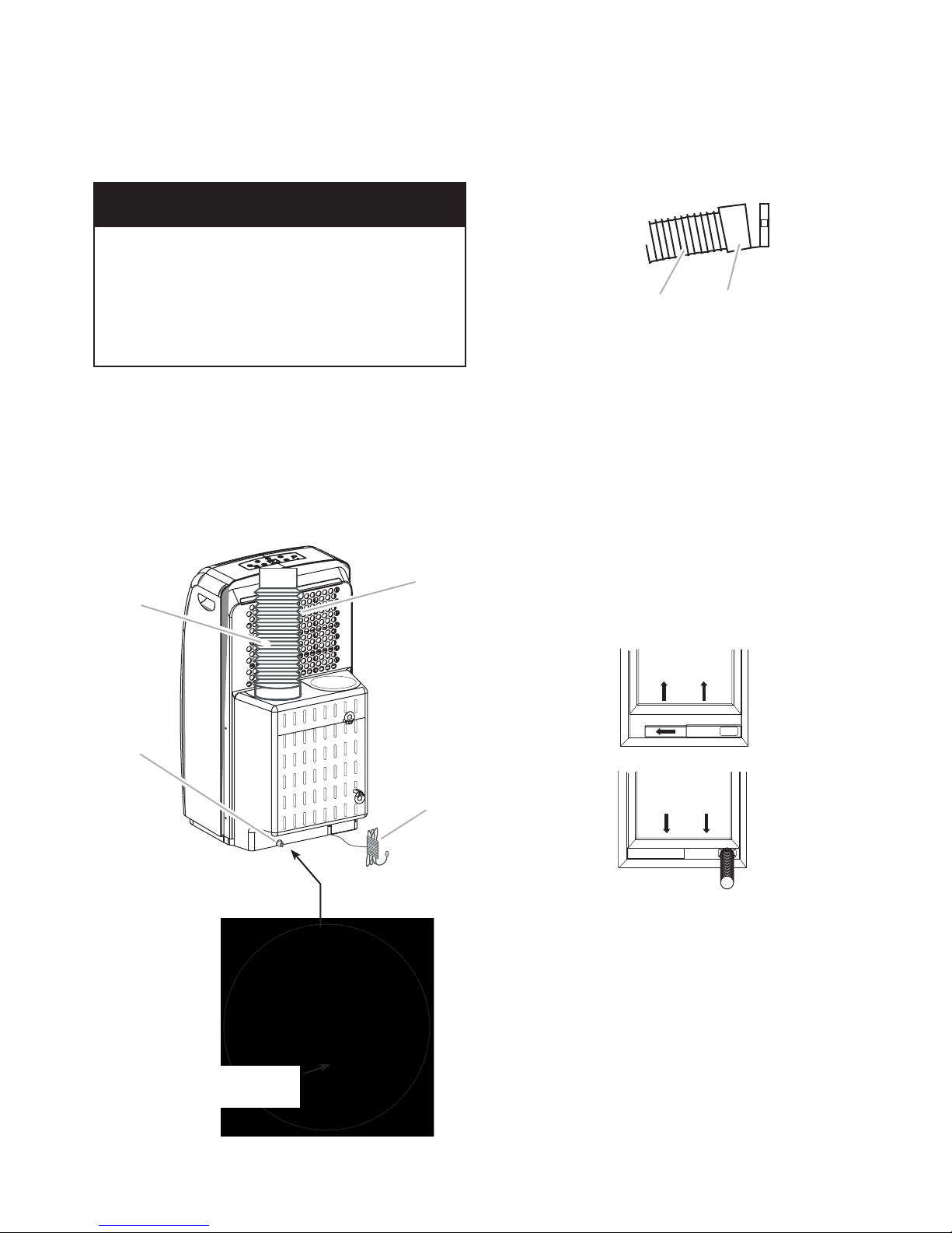
INSTALLATION INSTRUCTIONS
A. Flexible exhaust hose
B. Evaporator a
ir intake
C. Power supply
D. Drain port
B
A
C
D
A. Flexible exhaust hose
B. Window exhaust adapter
B
A
INSTALL PORTABLE
AIR CONDITIONER
Excessive Weight Hazard
Use two or more people to move and
install air conditioner.
Failure to do so can result in back or
other injury
Install Exhaust Hose And Adapter
1. Roll air conditioner to its selected location. See “Location Requirements.”
Insert flexible exhaust hose into opening
2.
in back of air conditioner.
3. Twist clockwise to lock hose into place.
.
4. Attach window exhaust adapter to the
flexible exhaust hose. Turn clockwise until securely locked into place.
Window Installation
The window slider kit has been designed to fit
most standard vertical and horizontal window
applications. However, it may be necessary
for you to modify some aspects of the installation procedures for certain types of windows.
Open the window.
1.
2. Place the window slider kit into the window, extending it to fit the width of the
window.
Vertical Slide Window
NOTE: For casement window installation, the
window slider kit may be installed vertically
with the window slider kit opening at the bottom.
Customer-Installed
Drain Hose
2-3
Page 14
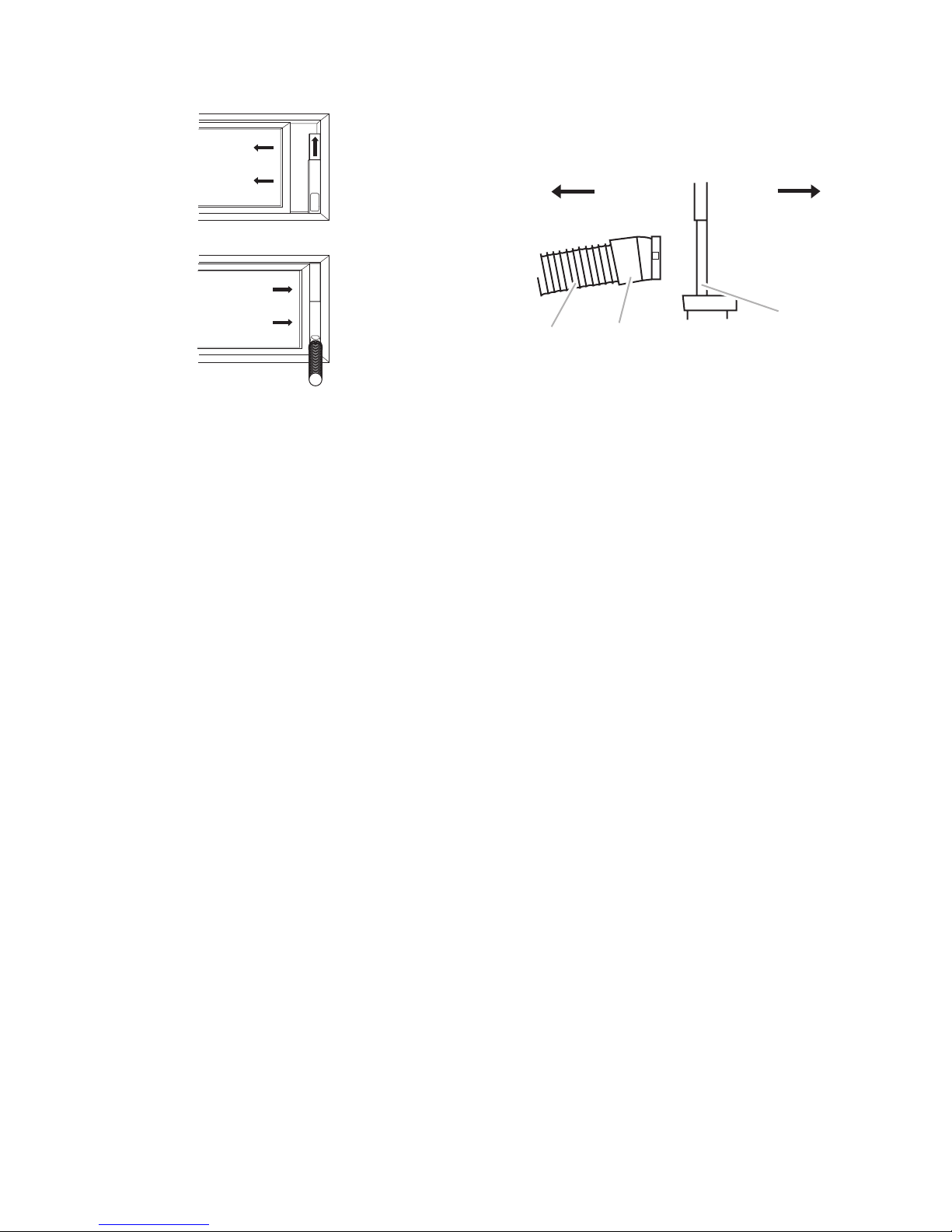
A. To air conditioner
B. O
utdoors
C. Window slider kit
D. Window exhaust adapte
r
E. Flexible exhaust hose
E
A B
D
C
Horizontal Slide Window
3. Close the window onto the window slider
kit to secure.
Insert the window exhaust adapter into
4.
the window slider kit.
2-4
Page 15

PRODUCT OPERATION
THEORY OF OPERATION
OPERATING MODES
The Whirlpool 10,000 BTU Portable Room Air
Conditioner has five main operating modes
and two modifiers:
Main Modes:
Cooling
•
ComfortMode
•
RapidCool
•
Dry
•
Fan Only
•
Modifiers:
Auto Fan
•
Swing Mode
•
Cooling
•
Mode: In the Cooling Mode the
customer can adjust the temperature setting
from 90°F to 64°F. The actual temperature
be displayed after the temperature ad-
will
justment
has been made. The compressor
and condenser fan motors cycle on or off
together. They will cycle on when the room
temperature is greater than 1°C, (approximately
point
2°F), away from the temperature set
and off at the same intervals below set
point. High, Low, or Auto fan speed may be
selected.
omfortMode
C
•
seeks to automatically cool the room to 73°F
(23°C). If the room temperature is greater
73°F, Cooling Mode will be used. If the
than
room
temperature is equal to or lower than
73°F, Dry Mode will be used. The default
temperature
by 4°F (2°C). Only the actual temperature
will be displayed.
™
RapidCool
•
Mode: RapidCool™ Mode may
only be selected using the remote control.
This mode automatically runs the evaporator
fan speed on high and the set point is set to
64°F (18°C).
™
Control
™
™
Control: ComfortMode
™
may be increased or decreased
•
Mode: The unit starts in the cooling
Dry
mode for three minutes to determine the
room air temperature at the thermistor. The
control creates a set point 3°F (1.5°C) cooler
room temperature and then operates
than
in the cooling mode with the evaporator fan
operating at low speed. This 3°F (1.5°C) differential
is needed to allow the compressor
to run long enough to chill the evaporator.
Set point temperature may be increased or
decreased by 4°F (2°C). Only the actual
temperature will be displayed.
Only Mode: In the fan only mode, only
Fan
•
the evaporator fan motor will run. High, Low
or Auto fan speed may be selected.
Auto Fan: The speed will be set automati-
•
based on room temperature. If the tem-
cally
perature
point,
is greater than 6°F (3°C) above set
the fan will run on high speed until set
point is reached.
wing Mode: When the unit is powered up in
S
•
any of the five operating modes, the air louver
motor opens the air louver to permit air from
the evaporator to flow into the room. Hold-
the fan speed button for three seconds
ing
or pressing the Swing button on the remote
will start the air door cycling up and down.
CONDENSATE WATER
MANAGEMENT
Condensate water from the evaporator drains
down into a sump in the unit base. As the water
level rises, the low water level switch closes, and
the water pump begins to circulate the water to
the top of the condenser. The water flows down
over the warm condenser, and is evaporated.
The water vapor is carried out the exhaust
duct. If the high water level switch closes, the
compressor and condensor fan motors shut
off, and the water full indicator LED lights. The
water must be drained manually.
3-1
Page 16

COMPRESSOR PROTECTION
FULL WATER WARNING
The control protects the compressor by not
allowing a compressor restart for 3 minutes.
This delay will occur when moving through the
operating modes with the remote or keypad or
if there are rapid temperature changes at the
thermistor.
DE-ICE PROTECTION
A de-ice thermistor is mounted on the end of
the evaporator in a tube brazed to the tubing
loops. When the de-ice thermistor senses 25°F
(–4°C) for a continuous 30 seconds, the compressor
a buzzer sounds. When the de-ice thermistor
senses higher than 41°F (5°C), normal operation resumes.
and condenser fan motors stop and
When the high water level switch closes, the
Water Full LED will flash and all operation will
cease. The consumer must manually drain the
sump by pulling the drain plug over a drain.
THERMISTOR FAILURE DEFAULT
To provide some cooling operation in the event
of a thermistor failure, the control will default
to the following settings if a thermistor is determined to be shorted or open.
•
Room
room temperature is set at 75°F (24°C).
De-ice
•
100°F (38°C).
temp thermistor is shorted or open;
thermistor shorted or open; assume
3-2
Page 17
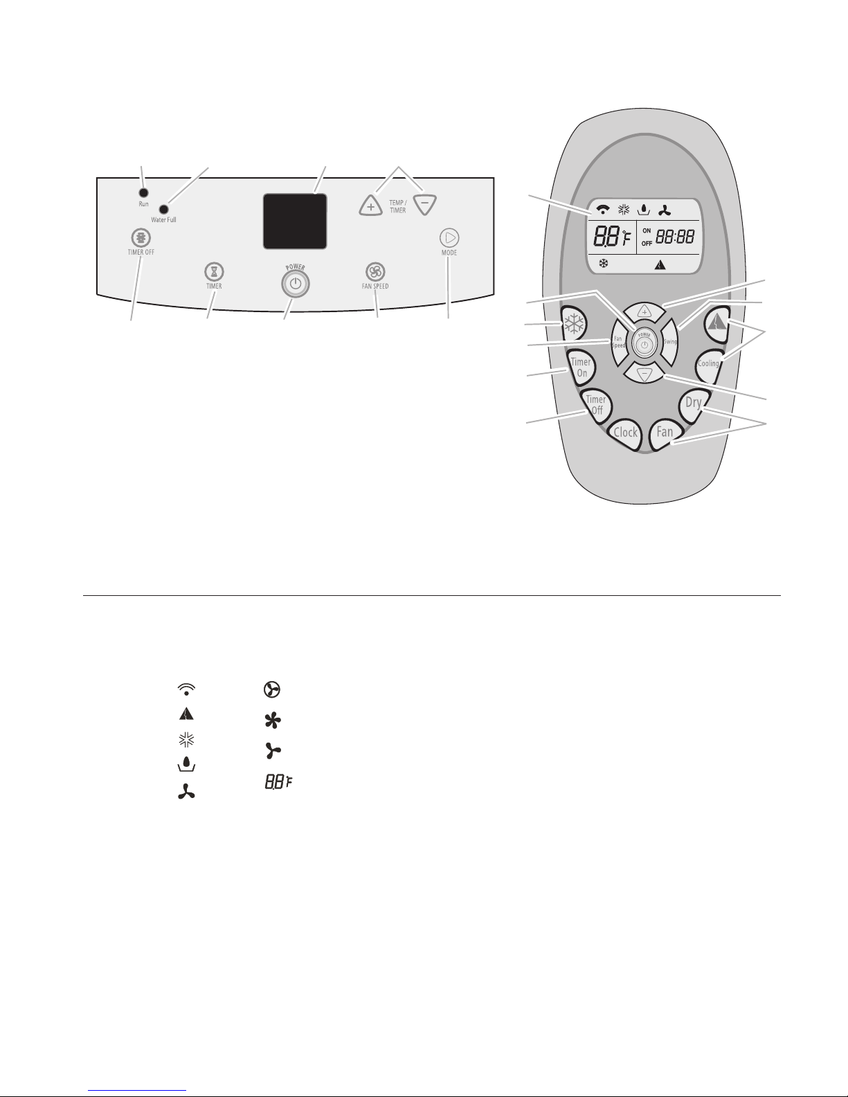
PORTABLE AIR CONDITIONER USE
A. Remote control
signal transmit
indicator light
indicator light
indicator light
B. ComfortMode
C. Cooling mode
D. Dry mode indicator
light
E
. Fan only mode
indicator light
indicator light
indicator light
indicator light
F. Auto fan speed
G. High fan speed
H
. Low fan speed
I. Display set
temperature
F
G
H
I
A
B
C
D
E
TM
A. RUN indicator light
B. WATER FU
LL indicator light
C. Display
D. TEMP/TIME plus and minus buttons
E. TIMER OF
F button
F. TIMER on b
utton
G. POWER button
H. FAN SPEED button—choose Auto, High or Low
I. MODE button—choose ComfortMode
™
control,
Cooling, Dry or Fan Only
J. RapidCool
™
mode control
K. SWING a
ir direction control
B
C
G
E
H I
D
F
A
C
D
D
E
F
G
H
I
I
J
K
NOTES:
Remote control may vary in appearance.
•
Two AA batteries (not included) power the remote control. Do not
•
use rechargeable batteries. Replace batteries after 6 months of
use, or when the remote control starts to lose power.
To operate the air conditioner with the remote control, aim the
•
remote control at the signal receptor from no more than 23 ft
(7 m) away.
USING THE CONTROL PANEL
Display Symbols
3-3
NOTES:
The air conditioner display shows the current
•
room temperature and 24 hour clock.
the event of a power failure, your air con-
In
•
ditioner will operate at the previous settings
when the power is restored.
hen changing modes while unit is operating,
W
•
the compressor will stop for 3 to 5 minutes
before restarting. If a button is pressed dur-
this time, the compressor will not restart
ing
for another 3 to 5 minutes.
Cooling or Dry mode, the compressor and
In
•
fan will stop when room temperature reaches
set temperature.
Page 18

Mode
Press MODE to choose ComfortMode™ control,
Cooling, Dry, or Fan Only.
Cooling Mode
Cools the room. Temperature and fan speed
are set by the user.
1. Press MODE to choose Cooling.
2. Choose fan speed. See “Fan Speed.”
3. Choose temperature. See “Temperature.”
Press POWER to start the air conditioner.
4.
The RUN indicator light will glow green.
When WATER FULL indicator light glows
5.
red, air conditioner will turn off automati-
. See “Portable Air Conditioner Care”
cally
for directions on draining the air condi-
.
tioner
Dry Mode
Dries
Fan runs on Low only.
NOTES:
•
•
1.
2. Choose temperature. See “Tempera-
3.
4.
NOTES:
•
the room. Temperature is set by user.
mode should not be used to cool the
Dry
room.
mode does not require hot air outlet
Dry
hose.
Press MODE to choose Dry.
ture.”
Press POWER to start the air conditioner.
The RUN indicator light will glow green.
When WATER FULL indicator light glows
red, air conditioner will turn off automati-
. See “Portable Air Conditioner Care”
cally
for directions on draining the air condi-
.
tioner
Press
set temperature by 2°F (1°C), or press twice
to decrease set temperature by 4°F (2°C).
the minus button once to decrease the
Press
•
set temperature by 2°F (1°C), or press twice
to increase set temperature by 4°F (2°C).
the plus button once to increase the
3-4
Page 19

ComfortMode™ Control
Air conditioner automatically selects cool or
dry depending on room temperature. When in
Dry mode, unit automatically selects fan speed
and temperature. When in Cooling mode, unit
automatically selects temperature, but fan
speed may be selected by user.
1. Press MODE to choose ComfortMode
™
control. Compressor and fan will start automatically
based on room temperature.
RUN indicator light will glow green and air
swing will start.
During Cooling mode, fan speed may be
2.
changed. See “Fan Speed.”
When WATER FULL indicator light glows
3.
red, air conditioner will turn off automati-
. See “Portable Air Conditioner Care”
cally
for directions on draining the air condi-
.
tioner
NOTES:
Press
•
the minus button once to decrease the
set temperature by 2°F (1°C), or press twice
to decrease set temperature by 4°F (2°C).
Fan Speed
1. Press FAN to set the fan speed.
2. Choose Auto, High or Low.
•
Auto—Fan speed set automatically
•
High—Maximum cooling
•
Low—Minimum cooling
NOTE: Press and hold FAN SPEED for 3
seconds to change vertical airflow direction.
Press and hold FAN SPEED for 3 seconds
again to stop airflow louver at desired airflow
direction.
Temperature
1. Press the plus button to increase the temperature 2°F (1°C).
2. Press the minus button to decrease the
temperature 2°F (1°C).
•
Press
the plus button once to increase the
set temperature by 2°F (1°C), or press twice
to increase set temperature by 4°F (2°C).
Fan Only Mode
Serves
only to move air. Fan speed is set by
user.
1. Press MODE to choose Fan Only.
2. Choose fan speed. See “Fan Speed.”
3. Press POWER to start the air conditioner.
The RUN indicator light will glow green.
NOTES:
In the Cooling mode, the temperature can be
•
set between 64°F (18°C) and 90°F (32°C).
Fan Only mode, the temperature cannot
In
•
be set.
o change the temperature display from °F
T
•
to °C press and hold the plus and minus
buttons for 3 seconds.
Time Of Day
1. Press and hold TIMER and TIMER OFF.
“12:00” will be displayed.
Press the plus or minus button to set the
2.
time (24 hour clock).
3-5
Page 20
Timer Delay
To set the Timer for a 1- to 24-hour delay
until the air conditioner turns off (the air
conditioner must be On):
Press TIMER OFF. Timer “OFF 00:00”
1.
indicator light will flash.
2. Press the plus or minus button to change
the delay time (1 to 24 hours).
Press TIMER OFF again. Timer “OFF
3.
00:00” indicator light will remain on.
o set the Timer to turn on the air conditioner,
T
keeping previous settings:
Turn off air conditioner.
1.
2. Press TIMER. Timer “ON 12:00” indicator
light will flash.
To set the Timer to turn on the air conditioner, changing the previous settings:
1. Turn off air conditioner.
™
2. Adjust Mode to ComfortMode
control,
Cooling, Dry or Fan Only.
3. For Cooling mode:
Adjust fan speed to High, Low or Auto.
•
Adjust temperature between 64ºF
•
(18°C) and 90°F (32°C).
For Fan Only mode, adjust fan speed to
4.
High or Low.
™
5. For ComfortMode
control and Dry modes,
adjust temperature up or down by 4°F
(2.2°C).
NOTE: In Fan Only mode, temperature
cannot be set.
Press TIMER. Timer “ON 12:00” indicator
6.
light will flash.
3. Press the plus or minus button to change
the delay time (1 to 24 hours).
Press TIMER again. Timer “ON 12:00”
4.
indicator light will remain on.
7. Press the plus or minus button to change
delay time (1 to 24 hours).
Press TIMER again. Timer “ON 12:00”
8.
indicator light will remain on.
o clear Timer delay program:
T
NOTE: Air conditioner can be either on or off.
ress and hold TIMER OFF for 3 seconds.
P
Timer indicator light will turn off.
To see or change the remaining time (in
hours):
Press TIMER or TIMER OFF once after it
1.
has been programmed.
While the display is showing the remain-
2.
ing time, you can press the plus or minus
button to increase or decrease the time.
3-6
Page 21
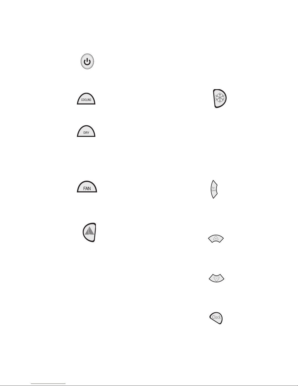
USING THE REMOTE CONTROL
RapidCool™ Mode
To turn the air conditioner on or off:
Press the power button.
Mode
1. Press COOLING to cool the room.
2. Press DRY to remove moisture from the
room without cooling.
NOTE: Dry operates on Low fan only.
Fan Speed button will not operate in this
mode.
Press FAN to run fan without cooling. Press
3.
FAN SPEED to choose High or Low.
Used for fast cooling. Automatically sets
fan speed to high and temperature to 64°F
(18°C).
™
NOTE: ComfortMode
operate in RapidCool
control button does not
™
mode.
1. Press RapidCool™ mode. The temperature
will automatically set to 64°F (18°C).
To turn RapidCool
2.
ComfortMode
™
mode off, press either
™
control, COOLING, DRY,
FAN, the power button or the plus or minus
buttons.
Fan Speed (in Cooling or Fan Only
modes only)
1. Press FAN SPEED.
2. Choose Auto, High or Low.
ComfortMode™ Control
1. Press ComfortMode™ control. The temperature and fan speed set automatically.
2. Press the up or down arrow button to increase or decrease the set temperature
4°F (2°C).
Press FAN SPEED to alternate between
3.
High and Low speeds each time Fan Speed
is pressed.
Temperature
To raise the temperature:
Press the plus button to increase the temperature 2°F (1°C).
To lower the temperature:
Press the minus button to decrease the temperature 2°F (1°C).
Time of Day
1. Press and hold CLOCK. “12:00” will be
displayed.
Press the plus or minus button to set the
2.
time.
3-7
Page 22
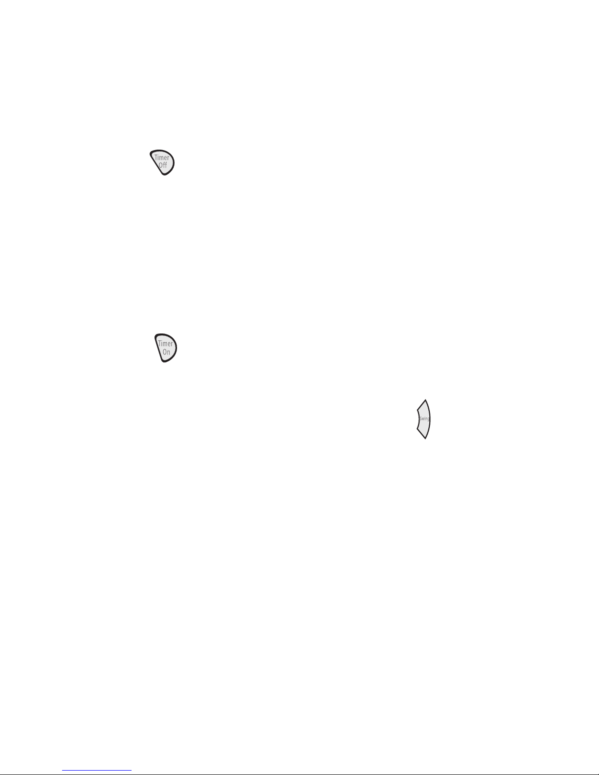
Timer Delay
To set the Timer for a 1- to 24-hour delay
until the air conditioner turns off (the air
conditioner must be On):
Press TIMER OFF. Timer “OFF 00:00”
1.
indicator light will flash.
Press the plus or minus button to change
7.
delay time (1 to 24 hours).
Press TIMER ON again. Timer “ON 12:00”
8.
indicator light will remain on.
o clear Timer delay program:
T
NOTE: Air conditioner can be either on or off.
Press and hold TIMER OFF for 3 seconds.
Timer indicator light will turn off.
Press the plus or minus button to change
2.
the delay time (1 to 24 hours).
Press TIMER OFF again. Timer “OFF
3.
00:00” indicator light will remain on.
o set the Timer to turn on the air condi-
T
tioner
, keeping previous settings:
1. Turn off air conditioner.
2. Press TIMER ON. Timer “ON 12:00” indicator light will fl
ash.
3. Press the plus or minus button to change
the delay time (1 to 24 hours).
Press TIMER ON again. Timer “ON 12:00”
4.
indicator light will remain on.
o set the Timer to turn on the air condi-
T
tioner
, changing the previous settings:
1. Turn off air conditioner.
™
2. Adjust Mode to ComfortMode
Cooling, Dry, Fan or RapidCool
control,
™
.
To see or change the remaining time (in
hours):
Press TIMER ON or TIMER OFF once
1.
after it has been programmed.
While the display is showing the remain-
2.
ing time, you can press the plus or minus
button to increase or decrease the time.
NOTE: Timer On and Timer Off can be set at
the same time.
CHANGING AIR DIRECTION
Press SWING (on remote control only) once to
change vertical airflow direction. Press again
to stop airflow louver at desired airflow direction.
NOTE: On the control panel, press and hold
FAN for 3 seconds to change vertical airflow
direction. Press and hold FAN for 3 seconds
again to stop airflow louver at desired airflow
direction.
3. For Cooling:
Adjust fan speed to High, Low or Auto.
•
Adjust temperature between 64°F
•
(18°C) and 90°F (32°C).
4. For Fan mode, adjust fan speed to High
or Low.
™
5. For ComfortMode
control and Dry modes,
adjust temperature up or down by 4°F
(2.2°C).
NOTE: In Fan mode, temperature cannot
be set.
Press TIMER ON. Timer “ON 12:00” indi-
6.
cator light will flash.
NORMAL SOUNDS
When your air conditioner is operating normally,
you may hear sounds such as:
roplets of water hitting the condenser, caus-
D
•
ing a pinging or clicking sound. The water
droplets help cool the condenser.
Air movement from the fan.
•
Clicks from the thermostat cycle.
•
ibrations or noise due to poor wall or window
V
•
construction.
high-pitched hum or pulsating noise caused
A
•
by the modern high-efficiency compressor
cycling on and off.
3-8
Page 23
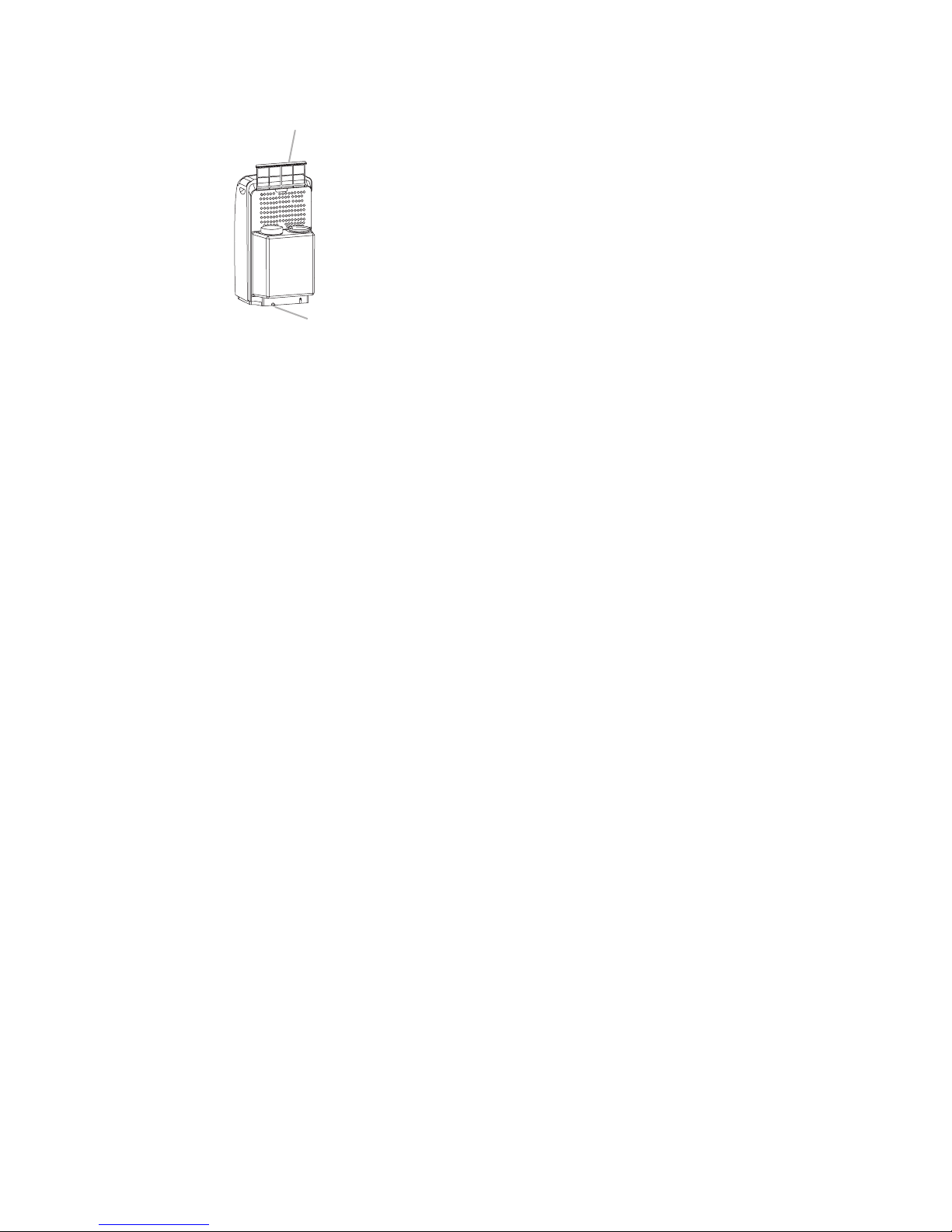
PORTABLE AIR CONDITIONER CARE
A. Air filter
B. Drain plug
A
B
DRAINING THE AIR CONDITIONER
1. Press POWER to turn off the air condi-
tioner.
2. Unplug air conditioner or disconnect
power.
3. Move the air conditioner to a drain location
or outside.
Remove the rubber drain plug and allow
4.
water to drain from the air conditioner.
5. Reinstall the drain plug.
CLEANING THE AIR FILTER
1. Press POWER to turn off the air conditioner.
2. Remove the filter by sliding it up.
3. Use a vacuum cleaner to clean the air filter.
If filter is very dirty, wash air filter in warm
water with a mild detergent.
NOTE: Do not wash air filter in the dish-
washer or use any chemical cleaners.
Air dry filter completely before replacing
4.
to ensure maximum efficiency.
CLEANING THE OUTSIDE
1. Unplug air conditioner or disconnect
power.
2. Remove the air filter and clean separately.
See “Cleaning the Air Filter.”
3. Wipe outside of air conditioner with a soft,
damp cloth.
6. Reposition air conditioner.
7. Plug in air conditioner or reconnect power.
8. Press POWER to start the air conditioner.
NOTE: A drain hose may also be connected to
drain port to drain water from air conditioner.
See “Install Portable Air Conditioner” on page
2-3 for location of drain port.
STORING AFTER USE
1. Remove drain plug and drain water completely.
2. Run unit with fan only for approximately
12 hours to dry the unit.
Unplug unit.
3.
4. Remove filter and clean. See “Cleaning
the Air Filter.”
5. Clean the outside of air conditioner. See
“Cleaning the Outside.”
Reinstall filter.
6.
Plug in air conditioner or reconnect power.
4.
5. Press POWER to start the air conditioner.
7. Remove batteries from remote control and
store with unit in a clean, dry area.
Remove air hose and store with unit in a
8.
clean, dry area. See “Installation Instructions.”
3-9
Page 24
TROUBLESHOOTING
Air conditioner will not operate
The power supply cord is unplugged. Plug
•
into a grounded 3 prong outlet. See “Electrical
Requirements.”
power supply cord has tripped (Reset
The
•
button has popped out). Press and release
RESET (listen for click; Reset button will latch
and remain in) to resume operation.
household fuse has blown, or circuit breaker
A
•
has tripped. Replace the fuse, or reset the circuit
breaker. See “Electrical Requirements.”
The Power button has not been pressed.
•
Press POWER.
The
•
A
breakers
•
•
•
•
•
Air conditioner power supply cord trips (Reset
button pops out)
local power has failed. Wait for power to
be restored.
ir conditioner blows fuses or trips circuit
oo many appliances are being used on the
T
same circuit. Unplug or relocate appliances that
share the same circuit.
ime-delay fuse or circuit breaker of the
T
wrong capacity is being used. Replace with a
time-delay fuse or circuit breaker of the correct
capacity. See “Electrical Requirements.”
An extension cord is being used. Do not use
an extension cord with this or any other appliance.
You are trying to restart the air conditioner
too soon after turning air conditioner off. Wait
at least 3 minutes after turning air conditioner off
before trying to restart the air conditioner.
You have changed modes. Wait at least 3
minutes after turning air conditioner off before
trying to restart the air conditioner.
An electrical overloading, overheating, pinch-
•
ing or aging can trip (Reset button will pop
out) the power supply cord. After correcting
the problem, press and release RESET (listen
for click; Reset button will latch and remain in)
to resume operation.
OTE: A damaged power supply cord must be
N
replaced with a new power supply cord obtained
from the product manufacturer and must not be
repaired.
Air conditioner seems to run too much
•
there a door or window open? Keep doors
Is
and windows closed.
•
current air conditioner replaced an older
The
model. The
use of more efficient components
may cause the air conditioner to run longer than
an older model, but the total energy consumption
will be less. Newer air conditioners do not emit
the “blast” of cold air you may be accustomed
to from older units, but this is not an indication
of lesser cooling capacity or efficiency. Refer to
the efficiency rating (EER) and capacity rating
(in BTU/hr.) marked on the air conditioner.
•
The air conditioner is in a heavily occupied
room, or heat-producing appliances are in
use in the room. Use exhaust vent fans while
cooking or bathing and try not to use heat-producing
appliances during the hottest part of the
day. A higher capacity air conditioner may be
required, depending on the size of the room
being cooled.
Air conditioner runs for a short time only, but
room is not cool
•
et temperature is close to room temperature.
S
Lower set temperature. See “Using the Control
Panel.”
•
Disturbances
trip (Reset button will pop out) the power
supply cord. Press and release RESET (listen
for click; Reset button will latch and remain in)
to resume operation.
in your electrical current can
3-10
Page 25
Air conditioner runs, but does not cool
The filter is dirty or obstructed by debris. Clean
•
the filter.
Air outlet is blocked. Clear air outlet.
•
S
•
et temperature is too high. Lower set tem
•
The air conditioner has lost charge (leak in
perature.
system), or operated in temperatures below
64ºF (18ºC). If the control buzzer beeps 3 times
repeatedly, contact service technician.
Air conditioner cycles on and off too much
•
The unit is set to ComfortMode
ComfortMode
™
control only when you are away
™
control. Use
from home or asleep, since the fan does not
circulate the room air continuously.
•
The air conditioner is not properly sized for
your room. Check the cooling capabilities of your
portable air conditioner. Portable air conditioners
are not designed to cool multiple rooms.
•
filter is dirty or obstructed by debris.
The
Clean the filter.
There is excessive heat or moisture (open
•
container cooking, showers, etc.) in the room.
Use a fan to exhaust heat or moisture from the
room. Try not to use heat-producing appliances
during the hottest part of the day.
The louvers are blocked. Install the air condi-
•
tioner
in a location where the louvers are free
from curtains, blinds, furniture, etc.
•
he outside temperature is below 64°F (18°C).
T
Do not try to operate your air conditioner in the
cooling mode when the outside temperature is
below 64°F (18°C).
•
temperature of the room you are trying to
The
cool is extremely hot. Allow extra time for the
air conditioner to cool off a very hot room.
Windows or doors to the outside are open.
•
Close all windows and doors.
Temperature on display does not match room
temperature
•
When
the compressor and fan motor turn off
during normal operations, or after you turn off
the unit, a lower temperature reading than the
actual room temperature may be displayed for
a short period of time. This lower temperature
reading is caused by the temperature sensor
being located close to the cold evaporator coil.
The actual room temperature will display within
a few minutes.
ater drips from cabinet into your house
W
•
The drain plug is not installed properly. Install
drain plug properly
.
Water Full indicator remains on, and the air
conditioner turns off.
•
is normal. See “Portable Air Conditioner
This
Care” for instructions on how to drain the air
conditioner.
3-11
Page 26

— NOTES —
3-12
Page 27
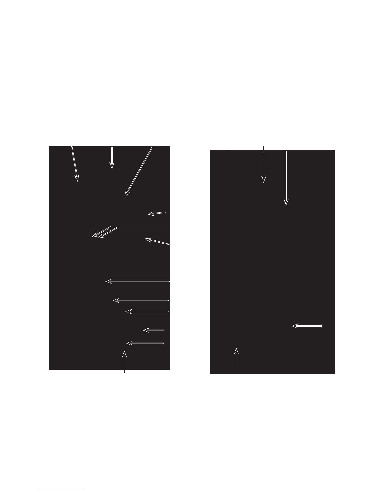
COMPONENT ACCESS
This section instructs you on how to service each component inside the 10,000 BTU Portable
Room Air Conditioner. The components and their locations are shown below.
COMPONENT LOCATIONS
Room Temp
Thermistor
Control Board
Receiver Board
Evaporator
Fan Motor
De-Ice
Thermistor
Transformer
Fan Motor
Capacitors
Louver
Motor
Evaporator
Low Water
Level Switch
(Viewed From Front Of Unit)
Not Shown: User Interface Board
Compressor
Capacitor
Overload
Protector
Compressor
Condenser
W
ater Pump
Motor
High W
Level Switch
ater
Condenser
Fan Motor
Power Supply
Cord Terminal
(Viewed From Rear Of Unit)
4-1
Page 28
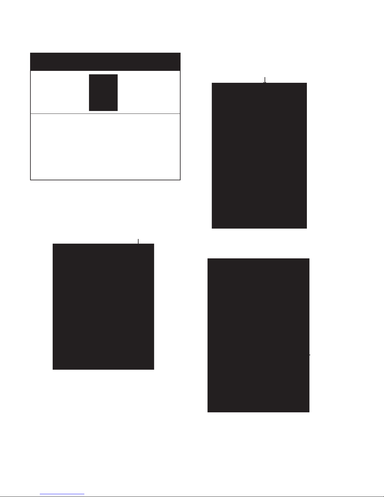
REMOVING THE CABINET
R
e
m
o
v
e
3. Remove the seven screws from the cabinet rear
.
Screw (1 of 7)
Electrical Shock Hazard
Disconnect power before servicing.
Replace all parts and panels before
operating.
Failure to do so can result in death or
electrical shock.
1. Unplug air conditioner or disconnect power.
2. Disconnect the vent duct from the air
conditioner by turning it counterclockwise
and lifting it off the vent opening.
Vent Duct
Cabinet
Rear
4. Pull the rear of the cabinet off the unit.
Cabinet
Rear
4-2
Page 29
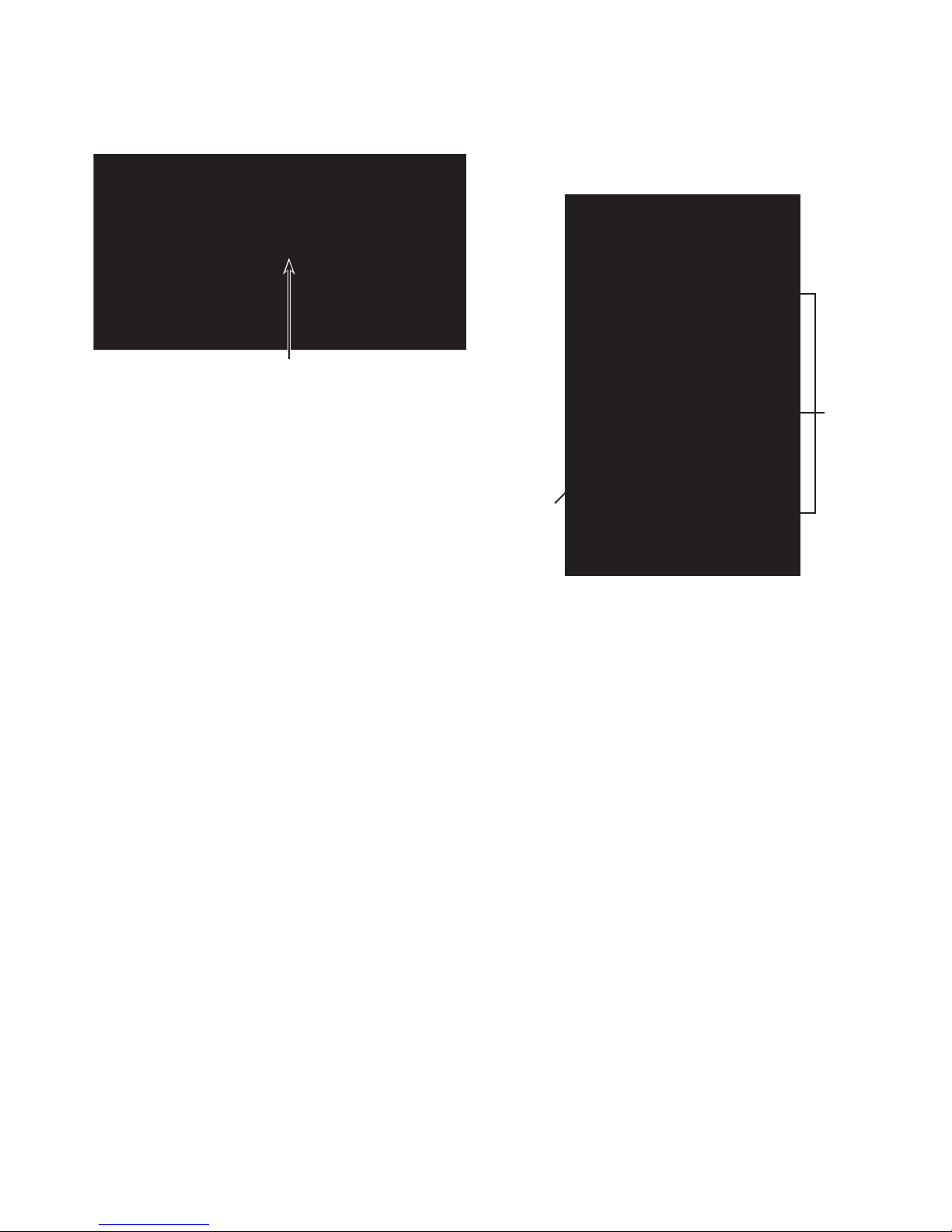
5. Disconnect the user interface connector
from the main harness.
User Interface Connector
6. Unsnap the cabinet front tabs from the
sides of the chassis, then lift the cabinet
to clear the vent opening, and remove
the cabinet from the unit.
3 Tabs
Cabinet Front
4-3
Page 30
REMOVING THE USER INTERFACE BOARD
Electrical Shock Hazard
Disconnect power before servicing.
Replace all parts and panels before
operating.
Failure to do so can result in death or
electrical shock.
1. Unplug air conditioner or disconnect power.
2. Remove the cabinet from the unit (see
page 4-2 for the procedure).
Position the cabinet front upside down so
3.
the user interface board is accessible.
4. Remove the six screws from the user interface board and remove the board from
the cabinet front.
User Interface Board 6 Screws
User Interface Board
User Interface Board
4-4
Page 31
REMOVING THE LOUVER MOTOR & RECEIVER BOARD
Receiver Board
Electrical Shock Hazard
Disconnect power before servicing.
Replace all parts and panels before
operating.
Failure to do so can result in death or
electrical shock.
1. Unplug air conditioner or disconnect power.
2. Remove the cabinet from the unit (see
page 4-2 for the procedure).
Remove the seven cover screws, and the
3.
green ground wire screw and lockwasher
from the components cover, and remove
the cover.
Louver MotorReceiver Board
CN20
CN13
Louver Motor Tie
Receiver Board Ties
b) Remove the two screws from the lou-
ver motor and remove the motor
Louver Motor Screws
.
Screws
Ground Wire Screw
Components Cover
Screws
4. Cut the wire tie for the louver motor, or
the two wire ties for the receiver board
(see the top right photo).
5. T
o remove the louver motor:
a) Disconnect the motor wire connector
CN13 from the control board.
6. T
o remove the receiver board:
a) Disconnect the board connector CN20
from the control board (see the top
photo).
Remove the two screws from the re-
b)
ceiver board and remove the board.
Receiver Board Screws
REASSEMBLY NOTE: Be sure to replace the
wire ties that you removed with new ties, and
secure the wires neatly together.
4-5
Page 32
De-I
ce
Thermistor (CN1-3 & CN1-4)
R
oom Temp
T
hermistor (CN1-1 & CN1-2)
Hi
g
h Water Level Sw (CN17
)
Low Water Level Sw (CN18
)
R
eceiver Board (CN20)
Louver Motor (CN13
)
C
ondenser Fan Motor (CN21
)
L
ight Blue Wire (CN9)
White Wire (CN10)
R
ed Wire (CN8
)
Red Wire (CN3
)
Dark Blue Wire (CN11)
B
lack Wire (CN6)
Yellow Wire
(CN4)
Yellow Wire (CN5
)
Yellow Wire (CN2
)
R
ed Transformer
Wires (CN12)
N/C (CN7)
White
Trans
f
ormer
Wires (CN14
)
B
rown Relay Wir
e
B
lack Relay Wir
e
REMOVING THE CONTROL BOARD
Electrical Shock Hazard
Disconnect power before servicing.
Wire Tie
Standoff
(1 of 6)
Replace all parts and panels before
operating.
Failure to do so can result in death or
electrical shock.
1. Unplug air conditioner or disconnect power.
2. Remove the cabinet from the unit (see
page 4-2 for the procedure).
Remove the components cover (see
3.
page 4-5 for the procedure).
Disconnect the wires from the control
4.
board and its components.
Control Board
Control
Board
5. Cut the wire tie around the user interface
board cable (see the top right photo).
Squeeze the tabs on the ends of the con-
6.
trol board standoffs, and lift the board off
the standoffs.
REASSEMBLY NOTE: Be sure to replace the
wire tie that you removed with a new one, and
secure the wires neatly to the chassis.
4-6
Page 33
REMOVING A FAN MOTOR CAPACITOR, COMPRESSOR
White
Red
Blue
MOTOR CAPACITOR, & TRANSFORMER
b) Disconnect the wires from the termi-
nals
of the evaporator or condenser
fan motor capacitor.
c) Remove the mounting screw from the
capacitor, and remove the capacitor
from the unit.
Electrical Shock Hazard
Disconnect power before servicing.
Replace all parts and panels before
operating.
Failure to do so can result in death or
electrical shock.
1. Unplug air conditioner or disconnect power.
2. Remove the cabinet from the unit (see
page 4-2 for the procedure).
Remove the components cover (see
3.
page 4-5 for the procedure).
Transformer
5. T
Screw
Evap.
Motor
Cap
Cond.
Motor
Cap
o remove the compressor motor ca-
pacitor:
a) CAUTION:
Discharge the capacitor
by touching the leads of a 20,000
ohm resistor to the motor capacitor
terminals.
Remove the capacitor clamp screw
b)
and remove the capacitor from the
clamp.
Disconnect the three wires from the
c)
capacitor terminals.
Screw
Evap. Fan
Motor Capacitor
4. T
o remove the evaporator or condens-
Cond. Fan
Motor Capacitor
er fan motor capacitor:
a) CAUTION:
Discharge the capacitor
by touching the leads of a 20,000
ohm resistor to the motor capacitor
terminals.
Clamp Screw
Compressor Motor
Capacitor
Compressor Motor
Capacitor Wires
Continued on the next page.
4-7
Page 34
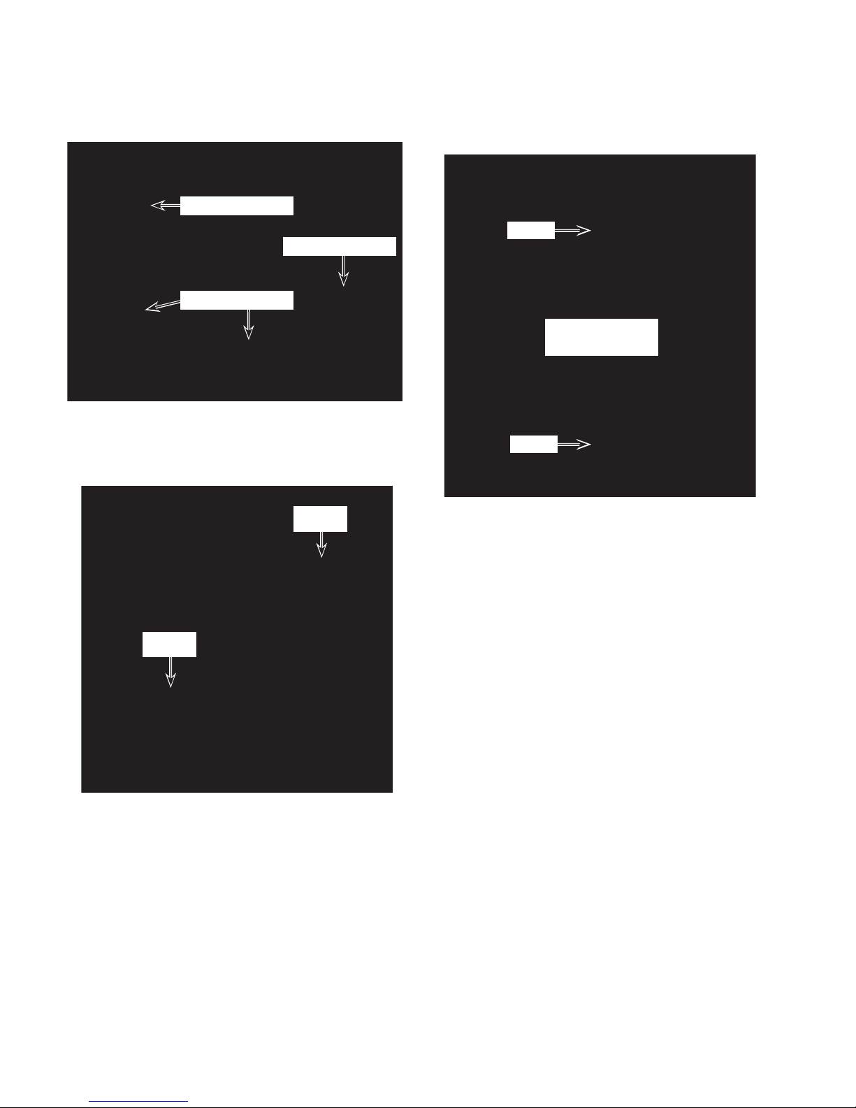
6. To remove the transformer:
a) Cut the two wire ties shown below.
Control Board
Transformer
Cut 2 Wire Ties
b) Disconnect the transformer wire con-
nectors
CN12 (red wires) and CN14
(white wires) from the control board.
c) Remove the two transformer screws
and remove the transformer from the
unit.
Screw
Transformer
Screw
CN14
CN12
REASSEMBLY NOTE: Be sure to replace the
wire ties that you removed with new ties, and
secure the wires neatly together.
4-8
Page 35
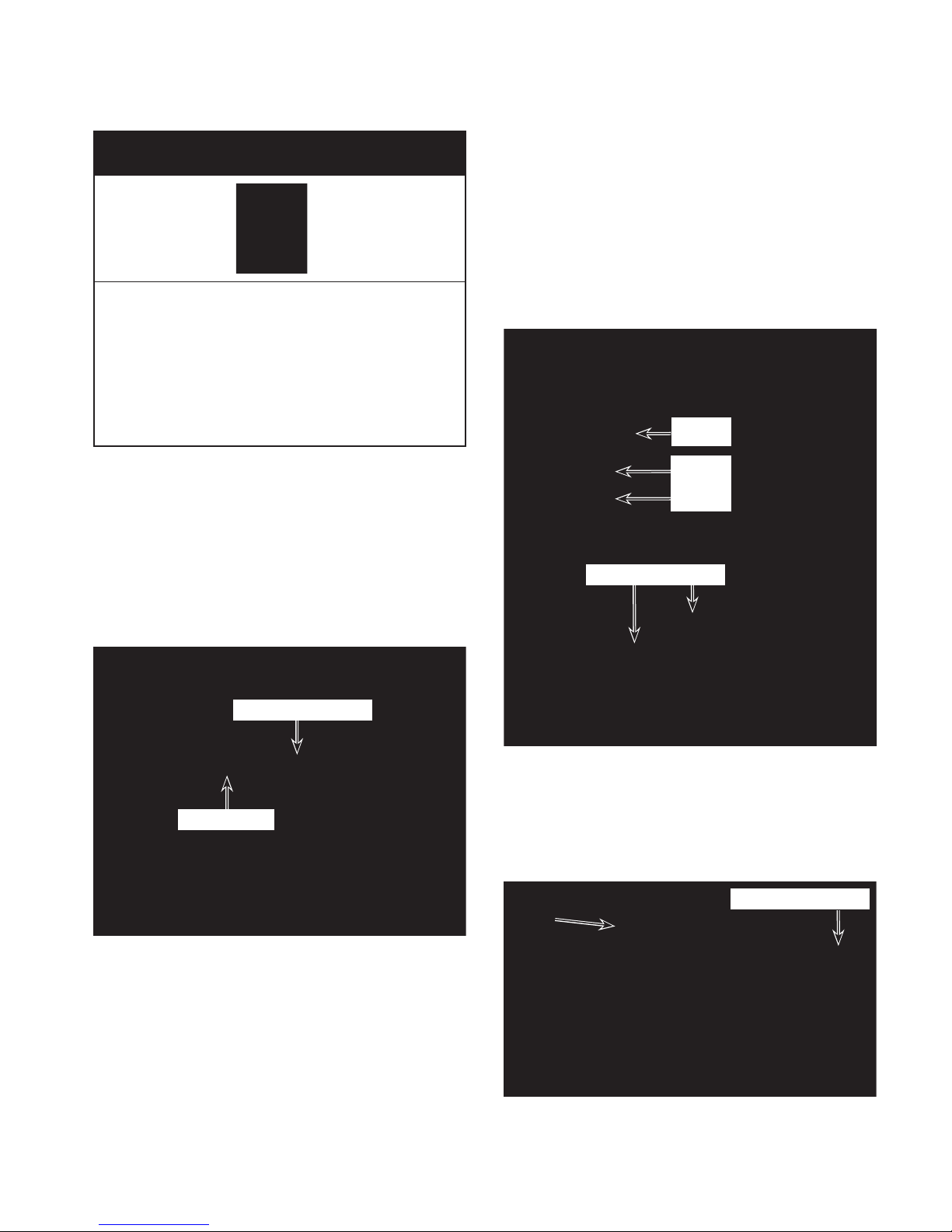
REMOVING THE EVAPORATOR FAN MOTOR
5. Disconnect the evaporator fan motor
wires from the following control board
connectors:
White wire at CN10
a)
b) Black wire at CN6
c) Yellow wire at CN4
Electrical Shock Hazard
Disconnect power before servicing.
Replace all parts and panels before
operating.
Failure to do so can result in death or
electrical shock.
1. Unplug air conditioner or disconnect power.
2. Remove the cabinet from the unit (see
page 4-2 for the procedure).
Remove the components cover (see
3.
page 4-5 for the procedure).
Cut the indicated wire tie from around the
4.
evaporator fan motor wires.
Evap. Fan Motor
6. Disconnect the two red wires from the
evaporator fan motor capacitor terminals.
CN10
CN6
CN4
Motor Cap Wires
Cut Wire Tie
7. Remove the louver motor from the louver
(see page 4-5 for the procedure).
Unhook the right end, pull the left end out
8.
of the housing hole, and remove the louver from the top of the unit.
Unhook Louver
Continued on the next page.
4-9
Page 36
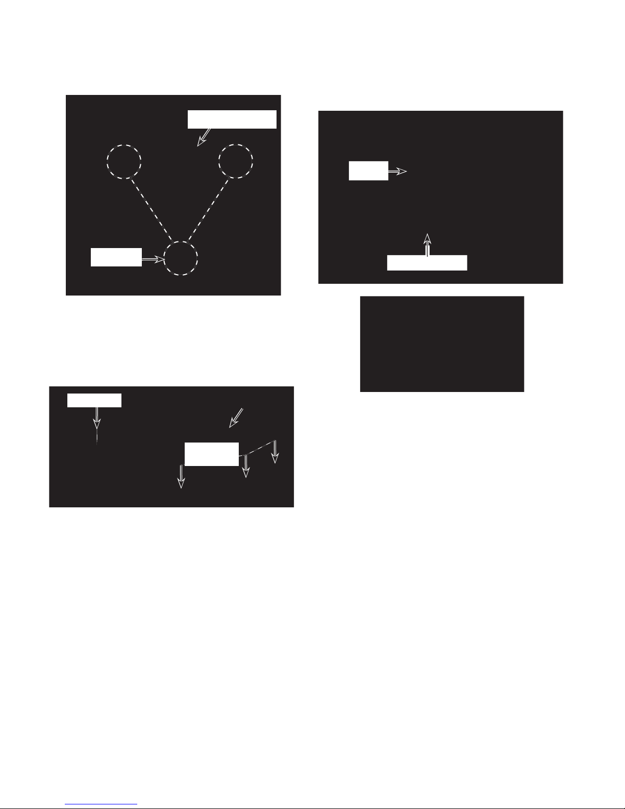
9. Remove the indicated three screws from
the evaporator fan motor.
Evap. Fan Motor
11. Remove the 10 mm fan nut from the fan
motor shaft and remove the motor from
the unit.
Fan
3 Screws
Remove the seven screws (three on
10.
each side and one on top) from the lou-
housing assembly, and lift the assem-
ver
off the top of the unit so that you can
bly
access the fan.
Louver Housing
Top Screw
Screws
Assembly
3 of 6
10 mm Fan Nut
Evaporator Fan Motor
REASSEMBLY NOTE: Be sure to replace the
wire tie that you removed with a new one, and
secure the wires neatly to the chassis.
4-10
Page 37
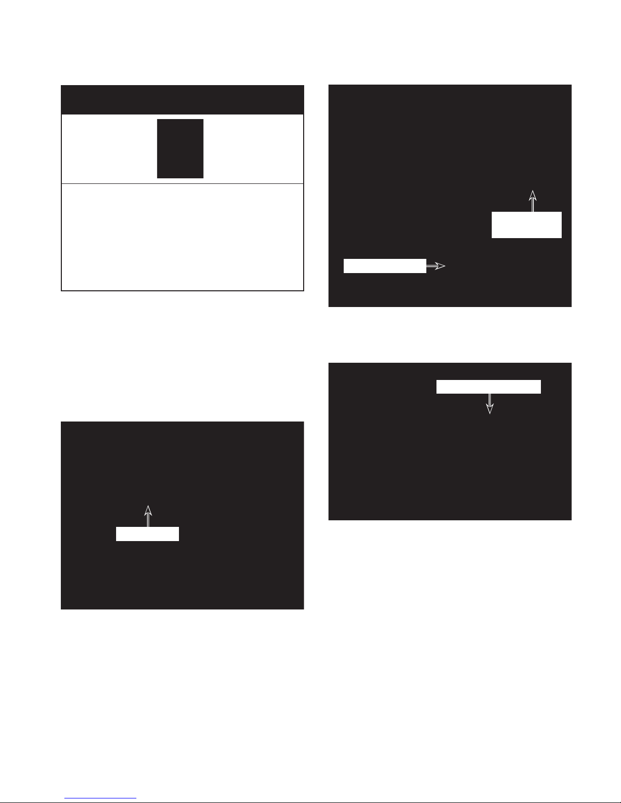
REMOVING THE ROOM TEMP AND DE-ICE THERMISTORS
Electrical Shock Hazard
Disconnect power before servicing.
Replace all parts and panels before
operating.
Failure to do so can result in death or
electrical shock.
1. Unplug air conditioner or disconnect power.
2. Remove the cabinet from the unit (see
page 4-2 for the procedure).
Remove the components cover (see
3.
page 4-5 for the procedure).
Cut the indicated wire tie from around the
4.
wires.
Room Temp
Thermistor
De-Ice Thermistor
5. Disconnect the room temp and de-ice
thermistor connector from the control
board at CN1.
Thermistor Connector
Cut Wire Tie
Continued on the next page.
4-11
Page 38
6. To remove the room temp thermistor,
unhook the wires and pull the thermistor
off the evaporator clip.
o remove the de-ice thermistor:
7. T
a) Cut the wire tie from around the evap-
orator tubing.
Pull the de-ice thermistor out of the
b)
evaporator housing.
Cut Wire Tie
Pull Thermistor
Out Of Housing
Pull Thermistor Off Clip
REASSEMBLY NOTE: Be sure to replace the
wire ties that you removed with new ties, and
secure the wires neatly together.
4-12
Page 39
WIRE TIE LOCATIONS
NOTE: The following photos show the loca-
tions (circled) of the various wire ties used in
the rest of this section, and are not called out
in the procedures. The wire ties will need to
be replaced to secure the wiring for the component being serviced. Always route the wires
as shown in the photos, and keep them neat
to avoid vibration noise.
(Viewed From Front Of Unit)
(Viewed From Right Side Of Unit)
4-13
Page 40
REMOVING THE WATER PUMP MOTOR
Electrical Shock Hazard
Disconnect power before servicing.
Replace all parts and panels before
operating.
Failure to do so can result in death or
electrical shock.
Water Pump Motor Screws
1. Unplug air conditioner or disconnect power.
2. Remove the cabinet from the unit (see
page 4-2 for the procedure).
Remove the components cover (see
3.
page 4-5 for the procedure).
Water Pump
Motor
Water Pump Mounting Plate Screws
Pry the end of the water tubing off the
6.
water pump mounting plate connector.
7. Unclip the five locking tabs from the impeller
cover, and remove the cover from
the pump.
Water Tubing
Impeller Cover Tab
4. Remove the two screws from the water
pump motor (see the top right photo).
Remove the three screws from the water
5.
pump mounting plate and lift the pump off
the housing.
4-14
Page 41
8. Remove the 5/16˝ nut from the impeller
and remove the impeller from the motor
shaft. NOTE: The thread is right-rotation.
Cut the necessary wire ties to remove
10.
the blue and red motor wires from the
chassis.
1. Disconnect the motor wires from the con-
1
trol board terminals CN8 (red) and CN9
(blue).
CN9 (Blue)
CN8 (Red)
Impeller Nut
9. Use a hammer, and tap the end of the
motor shaft to remove the water pump
motor from the impeller and housing.
Impeller
Motor Shaft
Control Board
REASSEMBLY NOTE: Be sure to replace all
of the wire ties that you removed with new
ties, (see page 4-13 for the locations), and
secure the wires neatly together.
4-15
Page 42
REMOVING THE HIGH & LOW WATER LEVEL SWITCHES
Mounting Plate
3 Screws
Electrical Shock Hazard
Disconnect power before servicing.
Replace all parts and panels before
operating.
Failure to do so can result in death or
electrical shock.
5. Loosen the nut from the water level switch
1. Unplug air conditioner or disconnect power.
2. Remove the cabinet from the unit (see
page 4-2 for the procedure).
Remove the components cover (see
3.
page 4-5 for the procedure).
you are servicing, and slide the switch
off the plate. IMPORTANT NOTE: Make
that you position the rubber seal on
sure
the switch so it is between the bottom of
the nut and the top of the mounting plate
when you install the switch.
High & Low Water
Level Switches
4. Remove the three screws from the water
level switch mounting plate and remove
the plate and switches (see the top right
photo).
Nut
Seal
Low Water
Level Switch
Nut
High Water
Level Switch
4-16
Page 43

6. Cut the necessary wire ties to remove
the high and low water level switch wires
from the chassis.
Disconnect the high water level switch
7.
connector from the control board at
CN17 (red), or the low water level switch
at CN18 (white).
CN17 (Red)
CN18 (Wht)
Pull the water level switch wire through
8.
the mounting plate and remove the
switch.
Water Level Switch
REASSEMBLY NOTE: Be sure to replace all
of the wire ties that you removed with new
ties, (see page 4-13 for the locations), and
secure the wires neatly together.
4-17
Page 44
REMOVING THE CONDENSER FAN MOTOR
Electrical Shock Hazard
Disconnect power before servicing.
Replace all parts and panels before
operating.
Failure to do so can result in death or
electrical shock.
1. Unplug air conditioner or disconnect power.
2. Remove the cabinet from the unit (see
page 4-2 for the procedure).
Remove the components cover (see
3.
page 4-5 for the procedure).
4. Remove the 7 screws from the fan motor
cover and remove the cover.
7 Screws
Fan Cover
Cond. Fan
Motor
5. Loosen the 5/16˝ hex-head fan screw on
the condenser fan motor, and pull the fan
off the motor shaft.
Fan Screw
4-18
Page 45
Remove the four screws from the con-
6.
denser fan motor
.
11. Disconnect the two red wires from the termials of the condenser fan motor capacitor.
n
12. Unlock and disconnect the 3-wire con-
nector from the control board at CN21.
CN21
Fan Motor
Screws
7. Remove the screw from the condenser
fan motor green ground wire.
Raise the locking tab on the wire tie
8.
standoff, and pull the strap and wires out
of the standoff.
9. Cut the indicated wire tie from the wires.
Standoff
Cond. Fan Motor
Capacitor Wires
13. Pull the condenser fan motor wires
through the cover.
Condenser Fan Motor
Wire Tie
Motor Ground
Cut the remaining wire ties that are nec-
10.
essary to remove the condenser fan motor wires from the chassis.
REASSEMBLY NOTE: Be sure to replace all
of the wire ties that you removed with new
ties, (see page 4-13 for the locations), and
secure the wires neatly together.
4-19
Page 46
REMOVING THE OVERLOAD PROTECTOR
AND THE COMPRESSOR
5. To remove the overload protector:
a) Remove the 5/16˝ nut from the termi-
nal cover and remove the cover.
Electrical Shock Hazard
Disconnect power before servicing.
Replace all parts and panels before
operating.
Failure to do so can result in death or
electrical shock.
1. Unplug air conditioner or disconnect power.
2. Remove the cabinet from the unit (see
page 4-2 for the procedure).
Remove the components cover (see
3.
page 4-5 for the procedure).
Overload
Protector
Nut
Terminal Cover
b) Disconnect the wire from the overload
protector terminal, and the overload
protector wire from the compressor
terminal (C), then remove the overload protector and coil.
Overload
Protector
& Coil
4. CAUTION: Discharge the capacitor by
touching the leads of a 20,000 ohm
resistor to the motor capacitor terminals.
Compressor
Connector C
Overload Protector
& Coil
4-20
Page 47
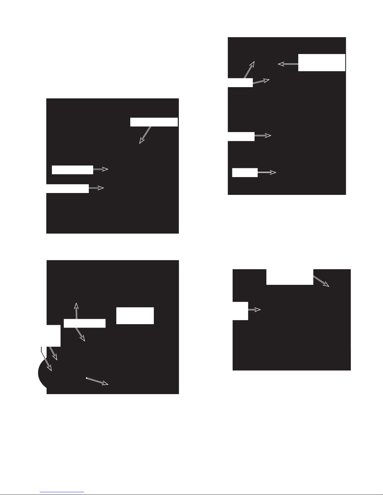
6. To remove the compressor:
a) Remove the overload protector (see
step 5).
Disconnect the black (R) and red (S)
b)
wires from the compressor terminals.
Remove the rubber gasket.
c)
Rubber Gasket
Suction Line
To Accumulator
Wire Ties
Accumulator
Red Wire (S)
Black Wire (R)
d) Peel back the two Velcro
move the cover from the compressor.
Velcro Straps
Nut &
Shock
Mount
®
straps and re-
Compressor
Cover
Wire Tie
g) Braze on an access valve and dis-
charge
the sealed system refrigerant
into an approved refrigerant recovery
system.
Disconnect the high side line from the
h)
compressor, and the suction line from
the accumulator.
High Side Line
To Compressor
Suction Line To
Accumulator
e) Cut the wire ties from the accumulator
covering, and from the covering on the
suction line to the accumulator (see
the top right photo).
Carefully peel the adhesive covering
f)
off the accumulator and the suction
line to the accumulator.
i) Remove the three 1/2˝ hex nuts from
the base of the compressor (see the
small inset in the lower left photo).
Lift the compressor off the unit and re-
j)
move
the three rubber shock mounts
from the base.
REASSEMBLY NOTE: Be sure to replace the
wire ties that you removed with new ties, and
secure the wires neatly together.
4-21
Page 48
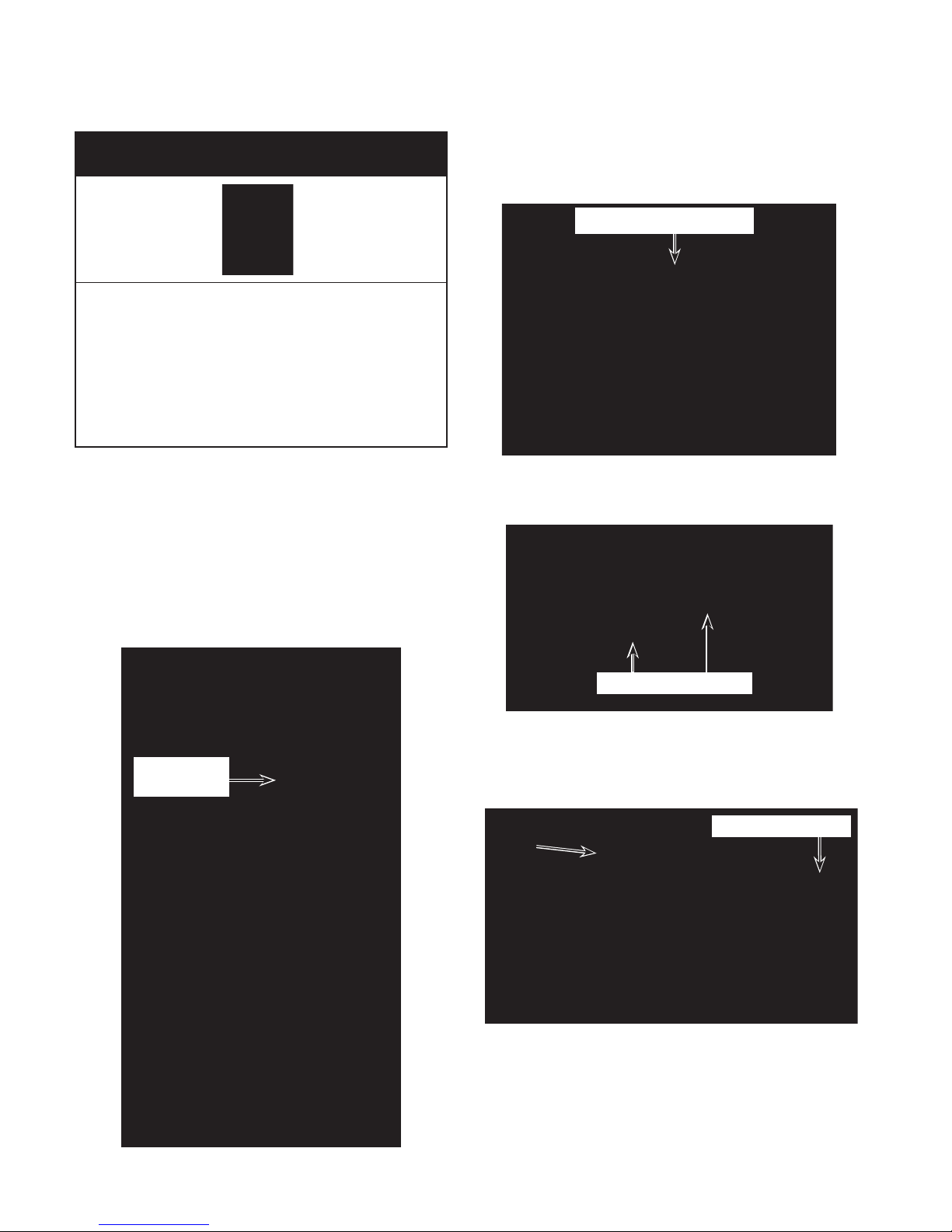
REMOVING THE EVAPORATOR
Electrical Shock Hazard
Disconnect power before servicing.
Replace all parts and panels before
operating.
Failure to do so can result in death or
electrical shock.
5. Pull the mounting clip off the evaporator
tubing and reinstall it on the replacement
evaporator at the same location.
Pull Clip Off Evaporator
1. Unplug air conditioner or disconnect power.
2. Remove the cabinet from the unit (see
page 4-2 for the procedure).
Position the unit with the rear of the unit
3.
facing you.
Remove the room temp thermistor from
4.
the mounting clip.
Room Temp
Thermistor
Remove the two screws from the louver
6.
motor and remove the motor.
Louver Motor Screws
7. Unhook the right end, pull the left end out
of the housing hole, and remove the louver from the top of the unit.
Unhook Louver
4-22
Page 49
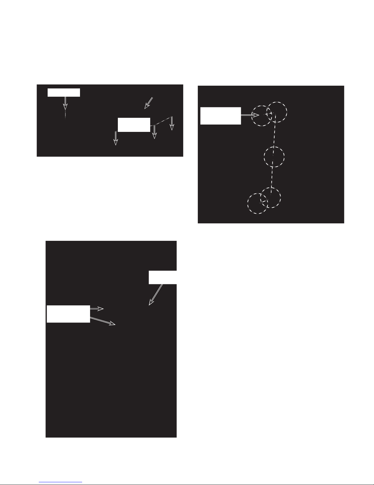
8. Remove the seven screws (three on
each side and one on top) from the lou-
housing assembly, and lift the assem-
ver
off the top of the unit so that you can
bly
access the fan.
Louver Housing
Top Screw
Screws
Assembly
3 of 6
9. Cut the wire tie and pull the de-ice therm-
stor out of the housing in the evaporator.
i
10. Remove the wire ties and foam insula-
from around the evaporator inlet and
tion
outlet tubing.
1. Braze on an access valve and discharge
1
the sealed system refrigerant into an approved refrigerant recovery system.
12. Measure the new evaporator inlet and
outlet tubes, and cut the existing lines to
the proper lengths.
Remove the ten mounting screws (five
13.
on each side) from the evaporator.
5 Evaporator
Screws
14. Lift the evaporator out of the unit.
Inlet & Outlet
Tubing Insulation
REASSEMBLY NOTE: Be sure to replace the
wire ties that you removed with new ties, and
secure the wires neatly together.
De-Ice
Thermistor
4-23
Page 50
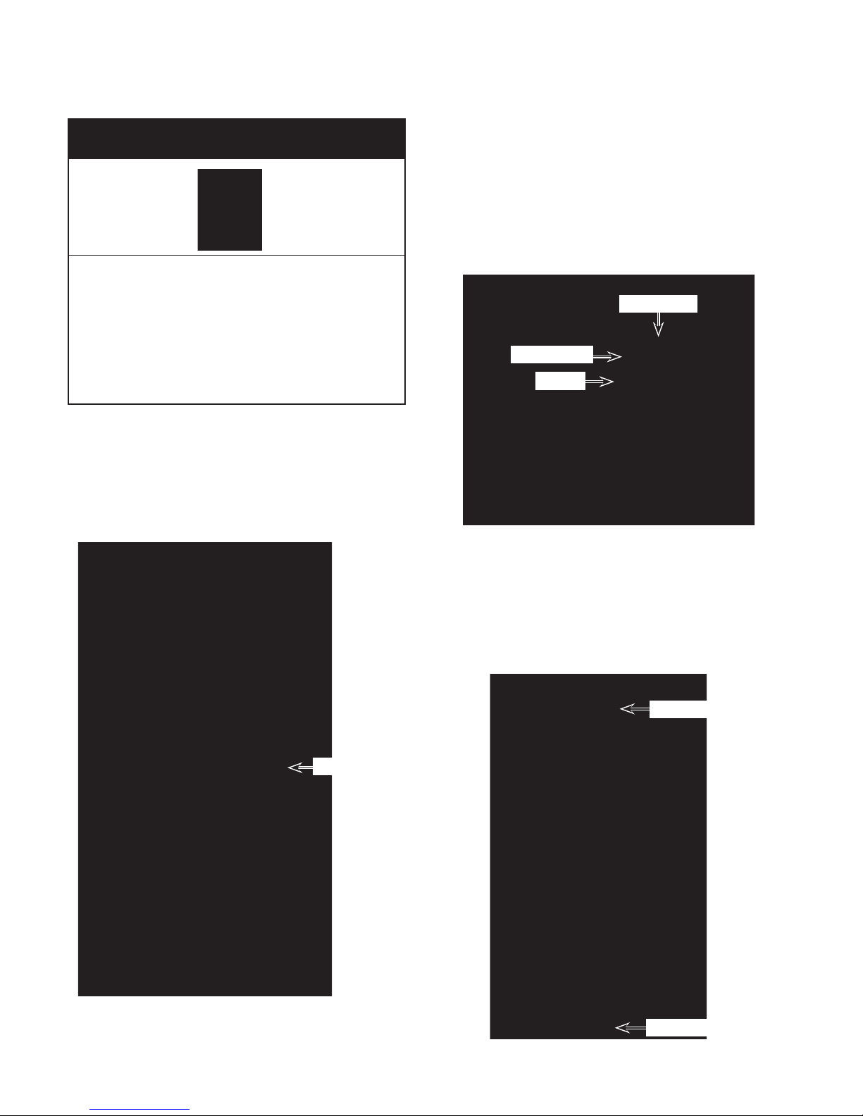
REMOVING THE CONDENSER
Electrical Shock Hazard
4. Pull the water tube off the water tray nozzle.
Remove the two screws (one on each
5.
side) from the water tray.
6. Slide the water tray back so it clears the
two top drain nozzles, and remove the
tray from the top of the condenser.
Disconnect power before servicing.
Replace all parts and panels before
operating.
Failure to do so can result in death or
electrical shock.
1. Unplug air conditioner or disconnect power.
2. Remove the cabinet from the unit (see
page 4-2 for the procedure).
Position the unit with the rear of the unit
3.
facing you.
Water Tray
Water Tube
Screw
7. Braze on an access valve and discharge
the sealed system refrigerant into an approved refrigerant recovery system.
Measure the new condenser inlet and
8.
outlet tubes, and cut the existing lines to
the proper lengths.
Inlet Tubing
Condenser
(Behind
Condenser
Fan Motor
Assy)
Outlet Tubing
4-24
Page 51
(seven on each side) from the condenser.
7 Condenser
Screws
10. Remove the condenser from the unit.9. Remove the fourteen mounting screws
4-25
Page 52
REMOVING THE POWER SUPPLY CORD
4. Remove the two screws from the terminal cover and remove the cover.
Electrical Shock Hazard
Disconnect power before servicing.
Replace all parts and panels before
operating.
Failure to do so can result in death or
electrical shock.
1. Unplug air conditioner or disconnect power.
2. Remove the cabinet from the unit (see
page 4-2 for the procedure).
Position the unit with the rear of the unit
3.
facing you.
Condenser Fan Motor Housing
Screws
Terminal Cover
5. Loosen the three terminal clamp screws,
and pull the flat pins on the ends of the
green, white, and black power supply
cord leads out of the clamp.
Flat Pin
Strain Relief
Power Supply Cord Terminal Cover
4-26
Grn Wht Blk
Using a 90˚ Phillips screwdriver, remove
6.
the screw from the strain relief plate, and
remove the strain relief and power supply
cord from the unit. NOTE: If you cannot
remove
the strain relief plate screw as
described, remove the eight screws from
the condenser fan motor housing (see
the left photo), and remove the housing
to access the strain relief.
Remove the screws inside the strain re-
7.
lief and remove the power supply cord.
Plate
Screw
Strain
Relief
Page 53
COMPONENT TESTING
1 5
Before testing any of the components, perform
the following checks:
The most common cause for control failure
•
is corrosion on connectors. Therefore, disconnecting
necessary throughout test procedures.
tests/checks should be made with a
All
•
VOM or DVM having a sensitivity of 20,000
ohms-per-volt DC, or greater.
and reconnecting wires will be
Electrical Shock Hazard
Disconnect power before servicing.
Replace all parts and panels before operating.
Failure to do so can result in death or electrical shock.
Check all connections before replacing
•
components, looking for broken or loose
wires, failed terminals, or wires not pressed
into connectors far enough.
Resistance
•
power cord unplugged from outlet, and
with wiring harness or connectors disconnected.
checks must be made with
LOUVER MOTOR
Refer
cessing the louver motor
1. Unplug air conditioner or disconnect power.
2. Disconnect the louver motor connector
3.
4. Insert a small test wire into each of the
5.
6. Clip the ohmmeter test leads to the test
to page 4-5 for the procedure for ac-
.
from the control board.
Insert a small test wire into pin 1 of the
louver motor connector.
remaining pins (2 - 5) in sequence to test
the motor windings.
Set the ohmmeter to the R x 1 scale.
wires. The meter should indicate between
190 and 210 Ω for each of the windings.
5-1
Page 54
Electrical Shock Hazard
Disconnect power before servicing.
Replace all parts and panels before operating.
Failure to do so can result in death or electrical shock.
FAN MOTOR & COMPRESSOR
MOTOR CAPACITOR
Fan Motor Capacitor
Compressor Motor
Capacitor
Refer to page 4-7 for the procedure for accessing a fan motor or compressor motor capacitor
1. Unplug air conditioner or disconnect power.
2. Discharge
3.
4.
.
the capacitor by touching
the leads of a 20,000 Ω resistor to the
terminals.
Disconnect the wires from the capacitor
terminals.
Set the ohmmeter to the R x 1K scale.
TRANSFORMER
Secondary
(White)
Primary
(Red)
Refer to page 4-7 for the procedure for accessing the transformer
1. Unplug air conditioner or disconnect power.
2. Disconnect the transformer wires from
the control board terminals.
Set the ohmmeter to the R x 1 scale.
3.
4. Touch the ohmmeter test leads to the
plug terminals with the primary (red)
transformer wires. The meter should indicate between 1
.
10 and 140 Ω.
5. Touch one of the ohmmeter test leads to
the capacitor terminals. The meter should
indicate several ohms, and gradually return to infinity
.
5. Touch the ohmmeter test leads to the
plug terminals with the secondary (white)
transformer wires. The meter should indicate approximately 2 Ω.
5-2
Page 55

Electrical Shock Hazard
Disconnect power before servicing.
Replace all parts and panels before operating.
Failure to do so can result in death or electrical shock.
EVAPORATOR FAN MOTOR
Refer to page 4-9 for the procedure for accessing the evaporator fan motor.
1. Unplug air conditioner or disconnect power.
2. Disconnect the fan motor wires from the
control board and capacitor terminals.
Set the ohmmeter to the R x 1 scale.
3.
4. Touch the ohmmeter test leads to the indicated fan motor wire connectors. The
meter should indicate as follows:
Red & red = between 125 and 145 Ω.
Yellow & black = between 25 and 45 Ω.
White & black = between 60 and 80 Ω.
Yellow & white = between 95 and 115 Ω.
One red & white = between 125 and 145 Ω.
Other red & white = continuity
CONDENSER FAN MOTOR
Refer to page 4-18 for the procedure for accessing the condenser fan motor.
1. Unplug air conditioner or disconnect power.
2. Disconnect the fan motor wires from the
control board and capacitor terminals.
Set the ohmmeter to the R x 1 scale.
3.
4. Touch the ohmmeter test leads to the indicated fan motor plug pins and wire connectors.
lows:
Motor W
Red & red = between 80 and 105 Ω.
Motor Plug Pins
Yellow & black = between 25 and 45 Ω.
White & black = between 30 and 50 Ω.
Yellow & white = between 60 and 80 Ω.
The meter should indicate as fol-
ires
Motor W
One red & white = between 80 and 105 Ω.
Other Red & white = continuity
ires & Plug Pin
5-3
Page 56
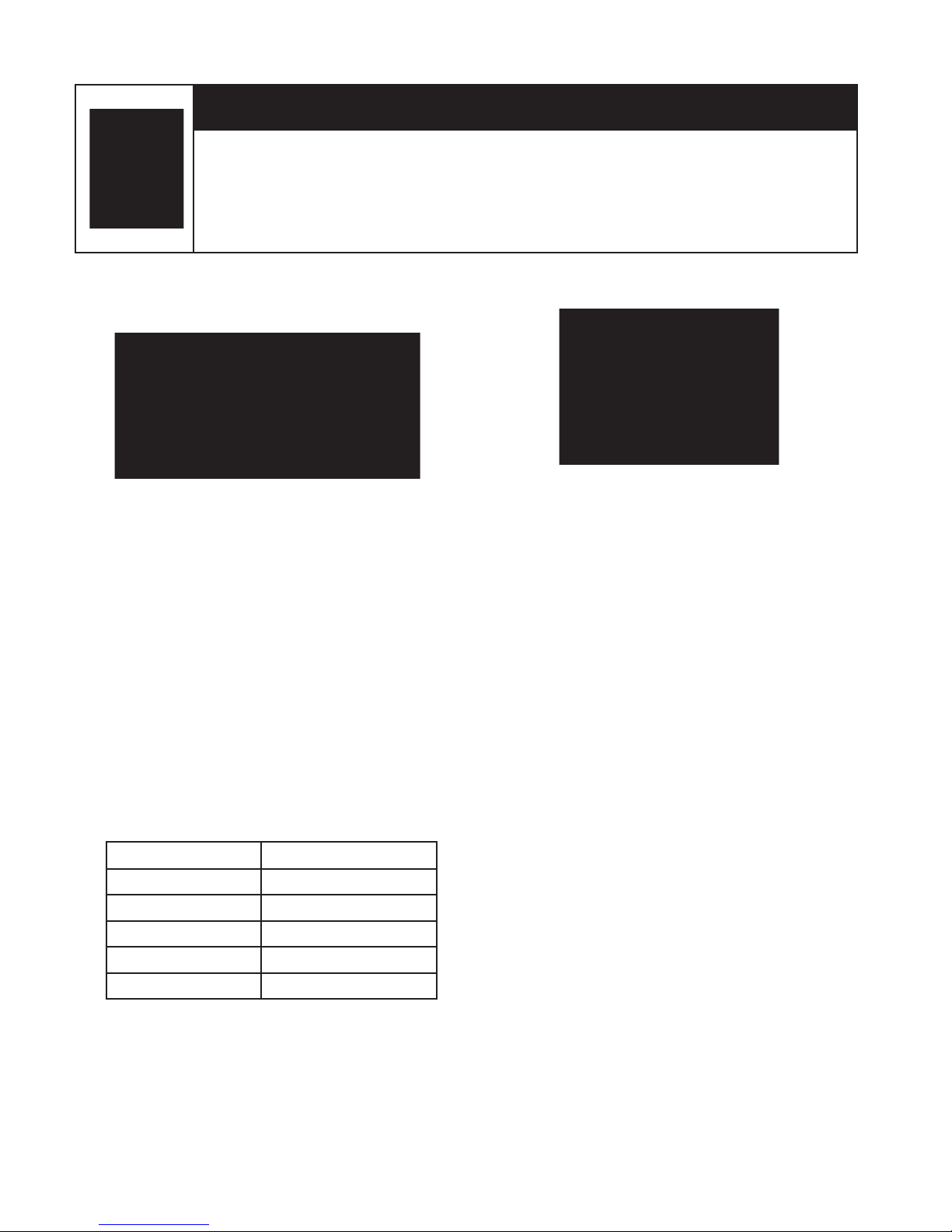
Electrical Shock Hazard
Disconnect power before servicing.
Replace all parts and panels before operating.
Failure to do so can result in death or electrical shock.
ROOM TEMP & DE-ICE
THERMISTORS
Refer to page 4-11 for the procedure for accessing the room temp and de-ice thermistors.
NOTE: The two thermistors are replaced as
an assembly
1. Unplug air conditioner or disconnect power.
2. Disconnect the room temp & de-ice
thermistor connector from the control
board terminals.
Set the ohmmeter to the R x 1 scale.
3.
4. Touch the ohmmeter test leads to plug
terminals 1 & 2 (room temp), and 3 & 4
(de-ice). The meter should indicate the
same resistance for either thermistor, as
shown in the following chart.
.
WATER PUMP MOTOR
Refer
cessing the water pump motor
1. Unplug air conditioner or disconnect power.
2. Disconnect the water pump motor wires
3.
4. Touch the ohmmeter test leads to the
to page 4-14 for the procedure for ac-
.
from the control board terminals.
Set the ohmmeter to the R x 1 scale.
wire terminals. The meter should indicate
between 15 and 35 Ω.
Temp. °F, (°C)
32 (0) 50900
72 (22) 17210
75 (24) 15700
77 (25) 15000
84 (29) 12530
Resistance, ±3%
5-4
Page 57

Electrical Shock Hazard
Disconnect power before servicing.
Replace all parts and panels before operating.
Failure to do so can result in death or electrical shock.
HIGH AND LOW WATER
LEVEL SWITCHES
Refer to page 4-16 for the procedure for accessing the high and low water level switches.
. Unplug air conditioner or disconnect power.
1
2. Disconnect the high or low water level
switch connector from the control board.
Set the ohmmeter to the R x 1 scale.
3.
4. Touch the ohmmeter test leads to the
plug terminals. The meter should indicate
an open circuit (infinite) with the switch
float down, and continuity (0 Ω) with the
float raised.
OVERLOAD PROTECTOR
Refer to page 4-20 for the procedure for accessing the overload protector.
1. Unplug air conditioner or disconnect power.
2. Discharge
pacitor by touching a 20,000 Ω resistor to the capacitor terminals.
Disconnect the overload protector wires.
3.
4. Set the ohmmeter to the R x 1 scale.
5. Touch the ohmmeter test leads to the
overload protector terminal and connec-
. The meter should indicate continuity
tor
(0 Ω).
the compressor motor ca-
5-5
Page 58
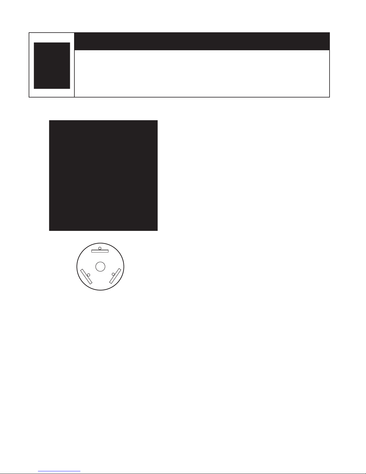
Black (C)
Red (R)
White (S)
Electrical Shock Hazard
Disconnect power before servicing.
Replace all parts and panels before operating.
Failure to do so can result in death or electrical shock.
COMPRESSOR
Refer to page 4-20 for the procedure for accessing the compressor.
1. Unplug air conditioner or disconnect power.
2. Discharge
the compressor motor capacitor by touching a 20,000 Ω resistor to the capacitor terminals.
Disconnect the three wires from the com-
3.
pressor terminals.
Set the ohmmeter to the R x 1 scale.
4.
5. Clip an ohmmeter test lead to the overload protector terminal C.
Touch the free test lead to the following
6.
compressor terminals. The meter should
indicate as shown:
erminal R = 2.5 Ω
T
Terminal S = 4.8 Ω
5-6
Page 59
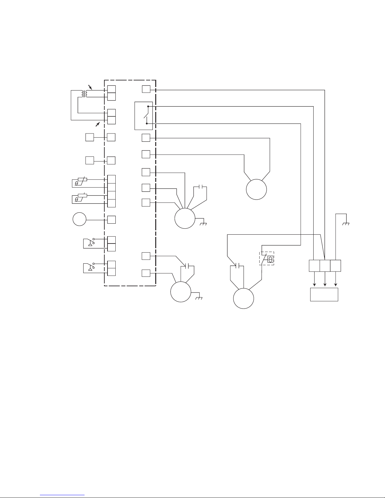
WIRING DIAGRAM
1
CN12
CN5
COM
NO
CN8
CN9
CN10
CN4
CN6
RD
TRANSFORMER
DISPLAY
UNIT
IR RECEIVER UNIT
EVAPORAT
OR FAN MOTOR
(INTERNAL PROTECTOR)
CONDENSER F
AN MOTOR
(INTERNAL PROTECTOR)
W
ATER PUMP MOTOR
(INTERNA
L PROTECTOR)
FAN MOTO
R
CAPACITOR
THERMISTO
R
(ROOM TEMP)
TH1
TH2
THERMISTO
R
(DE-ICE)
LOUVER MOTOR
LOW WATER LEVEL SW.
HIGH WATER LEVEL SW.
RD
RD RD
BU
BU
YL/GN
YL/GN
YL/GN
YL/GN
BU
BU
BN
BN
BU
120 VAC
BU
BN
BK
BU
RD
WH
WH
YL
BK
WH
CN14
CN16
CN20
CN1
CN13
CN18
CN11
CN19
CN15
3
1
2
1
2
3
4
1
2
CN17
CN3
1
2
M
M
M
M
CM
FAN MOTOR
CAPACITOR
COMPRESSOR
MOTOR
CAPACITOR
COMPRESSOR
MOTOR
OVERLOAD
PROTECTOR
RD
R
S
C
WH
RD
BK
115 VAC
60 Hz
CONTROL BOARD
GND
12-14 VAC
6-1
Page 60

— NOTES —
6-2
Page 61

— NOTES —
6-3
Page 62

— NOTES —
6-4
Page 63

PRODUCT SPECIFICATIONS
AND
W
ARRANTY INFORMATION SOURCES
IN THE UNITED STATES:
FOR PRODUCT SPECIFICATIONS AND WARANTY INFORMATION CALL:
FOR WHIRLPOOL PRODUCTS: 1-800-253-1301
FOR KITCHENAID PRODUCTS: 1-800-422-1230
FOR ROPER PRODUCTS: 1-800-447-6737
FOR TECHNICAL ASSISTANCE WHILE AT THE CUSTOMER’S HOME CALL:
THE TECHNICAL ASSISTANCE LINE: 1-800-253-2870
HAVE YOUR STORE NUMBER READY TO IDENTIFY YOU AS AN
AUTHORIZED SERVICER
FOR LITERATURE ORDERS:
P
FOR TECHNICAL INFORMATION AND SERVICE POINTERS:
www.servicematters.com
IN CANADA:
OR PRODUCT SPECIFICATIONS AND WARRANTY INFORMATION CALL:
F
1-800-461-5681
FOR TECHNICAL ASSISTANCE WHILE AT THE CUSTOMER’S HOME CALL:
THE TECHNICAL ASSISTANCE LINE: 1-800-488-4791
HAVE YOUR STORE NUMBER READY TO IDENTIFY YOU AS AN
AUTHORIZED SERVICER
HONE: 1-800-851-4605
Page 64

 Loading...