

Page 1

I..- ■ i:-iH
Electrical Requirements Page 3
Installation Instructions Page 6
use&care guide
How to Use Page 8
^Vhiгlpool
HOME ^ APPLIANCES
AIR CONDITIONER
Ovens, Compactors, Room Air Conditioners, Dehumidifiers, Automatic Washers, Clothes Dryers, Freezers, Refrigerator-Freezers, Ice Makers,Dishwa:
Page 2
IMPORTANT...
Please read this use and care guide before
installing or using your air conditioner.
It tells you how to install and operate it,
and gives important electrical informa
tion. Save it for future use in case you
may have a question or move the air
conditioner.
Copy your Model and
Serial Numbers here...
When you need service or call with a question, have
this information ready:
1. Complete Model and Serial Numbers. To
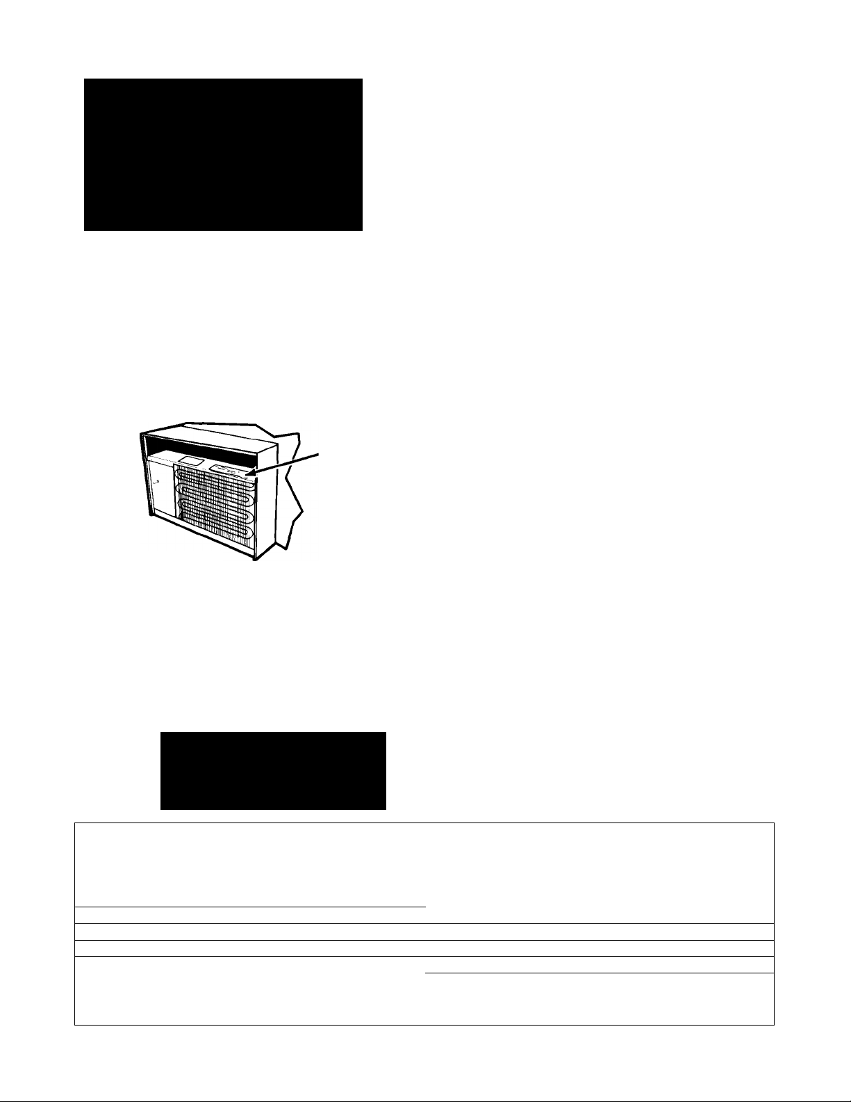
find Model and Serial Numbers remove the
front panel (see page 9). The numbers are
located on a label attached to the evaporator
coil cover near the top of the unit.
2. Purchase date from sales slip.
Copy this information in the spaces below.
Keep this book, your warranty and sales slip
together in a handy place.
Model Number
Serial Number
Purchase Date
Service Company and Telephone Number
CAUTION:
Handle the air conditioner with
care. Watch out for the sharp
metal fins on the front and
rear coils.
SERIAL LABEL
BEFORE YOU USE YOUR
AIR CONDITIONER
It is your responsibility to make
sure that your air con^tioner:
• Has been properly installed.
• Is the right size for the area you want
to cool.
• Is properly connected to electricity.
• Is properly electrically grounded.
• Is properly used only for the job it was
intended to do.
• Is not used by children or anyone not
able to operate it properly.
• Is properly maintained.
• Also, remove energy label and buy guide.
Use damp cloth to take off any glue
residue. Do not use a sharp instrument
or any harsh or abrasive cleaners.
Energy Saving Tips
Improve home insulation (seal doors,
windows, and close fireplace flue).
Close blinds or drapes on sunny side of
house; add window awnings.
Keep air filter clean. Don't block air flow
with drapes or furniture.
Ventilate attic (high temperature levels
add to normal cooling load).
Try not to use heat producing appliances
during the hottest part of the day. Turn
lights, radios, televisions, and other
appliances off when not needed.
Keep heat registers and cool air returns
closed or blocked off so cooled air won't
escape.
Use a vent fan in areas where cooking,
laundry, or bathing is done to pull out
extra heat and moisture near its source.
Before You Use Your Air Conditioner. .
Energy Tips................................................
Electrical Requirements............................
Installation Instructions
How to Start and
Use Your Air Conditioner
.............................
...........................
Contents
page
........
........
........
........
........
page
2
2
3
6
Cleaning and Caring for Your
Air Conditioner
Cooling Load Guide
Self-Service Checklist
Service Information
......................................
.............................
..........................
..............................
...............9
..........
10
..........
11
.............11
8
©1987 Whirlpool Corporation
Page 3

Electrical Requirements For Your Air Conditioner
BELOW ARE ELECTRICAL PLUG
VARIATIONS. CHOOSE THE ONE WHICH
MATCHES THE AMPERE RATING OF
YOUR UNIT. THE NUMBER OF AMPERES
IS PRINTED ON THE SERIAL LABEL,
ATTACHED TO THE FRONT OF THE UNIT,
BEHIND THE FRONT PANEL (SEE PAGE 2).
Chart-A
ELECTRICAL
REQUIREMENTS
For 115 volt models with serial plate amperes
up through 7.5.
OBSERVE ALL LOCAL GOVERNING CODES
AND ORDINANCES
Do not, under any circumstances, remove the
power supply cord ground prong.
PLOG TYPE
3-PRONG
GROUNDING PLUG
GROUND TYPE WALL
PRONG RECEPTACLE
POWER SUPPLY CORD
RECEPTACLE
FLAT BLADE
3- PRONG
GROUNDING
see ElEGTRICAL
llEQyiliEMENTS
For 115 volt models with
serial plate amperes up
through 7.5
For 230 volt and 230/208
volt models with serial
plate amperes up through
12.0
For 230 volt and 230/208
volt models with serial
plate amperes up through
16.0
RECEPTACLE WIRING
RECEPTACLE WIRING should be at least as
large as 14 gauge. Use copper wire only. It is the
personal responsibility and obligation of the
customer to provide proper and adequate
receptacle wiring installed by a qualified electri
cian. OBSERVE NATIONAL ELECTRICAL
CODE AND ALL LOCAL GOVERNING
CODES AND ORDINANCES.
Electrical Requirements
A 115 volt (103.5 min., 126.5 max.) 60 hertz AC
only, 15 ampere fused electrical supply is re
quired (time delay fuse or time delay circuit
breaker required.). It is recommended that a
separate circuit, serving oniy this appliance, be
provided. Do not use and extension cord.
Electrical Connection
Electrical Ground is Required on this Appliance
RECOMMENDED GROUNDING METHOD
For your personal safety, this appliance must be
grounded. This appliance is equipped with a
power supply cord having a 3-prong grounding
plug. To minimize possible shock hazard, the
cord must be plugged into a mating 3-prong
grounding type wall receptacle, grounded in
accordance with the National Electrical Code
and local codes and ordinances. If a mating wall
receptacle is not available, it is the personal
responsibility and obligation of the customer to
have a properly grounded 3-prong wall receptacle
installed by a qualified electrician. See Figure 1
on page 4.
Page 4
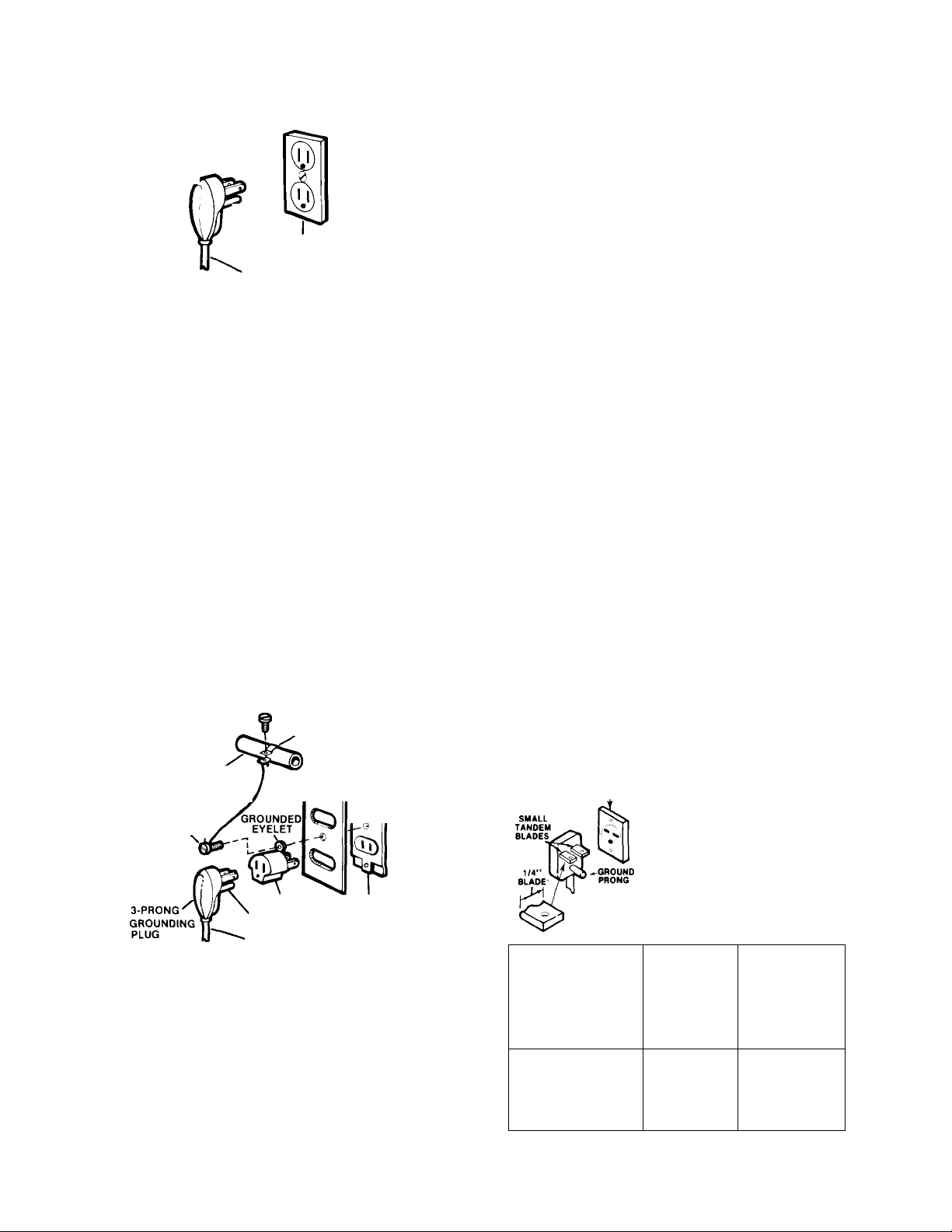
Figure 1
3-PRONG
GROUNDING PLUG
D J ELECTRICAL
D ) REQUIREMENTS
\
GROUND
PRONG 3- PRONG
POWER SUPPLY CORD
GROUNDING
TYPE WALL RECEPTACLE
ALTERNATE GROUNDING METHOD
If changing and properly grounding the wall
receptacle is impossible and where local codes
permit (consult your electrical inspector), a
temporary adapter may be plugged into the
existing 2-prong wall receptacle to mate with the
3-prong power supply cord. See Figure 2. THIS,
HOWEVER, IS NOT RECOMMENDED.
If this is done, you must connect the grounded
eyelet on the adapter to the wall receptacle
cover plate screw and from this same screw, you
must connect a separate copper ground wire
(#14 minimum) to a grounded cold water pipe.*
See Figure 2. Do not ground to a gas supply
pipe. Do not connect to electrical supply until
appliance is permanently grounded.
For 230 volt and 230/208 volt models with
serial plate amperes up through 12.0
Refer to Chart B for specific wiring and recep
tacle information to be used.
OBSERVE ALL LOCAL GOVERNING CODES
AND ORDINANCES.
Do not, under any circumstances, remove the
power supply cord ground plug.
ELECTRICAL GROUND
IS REQUIRED ON
THIS APPLIANCE.
A three-wire, single-phase 60 hertz AC only
electrical supply is required.
A separate electrical supply is required on a
separately fused circuit. Do not fuse groundneutral.
See Chart B for receptacle voltage requirements,
proper fuse size, wire and wiring connections
which must conform with rating of the appliance.
Do not use an extension cord.
Figure 2
GROUND ASSEMBLY
(ATTACH TO GROUNDED
METAL COLD
ELECTRICALLY
GROUNDED METAL
COLD WATER PIPE
(REMOVE PAINT, etc.)
WATER PIPE)
COVER PLATE
di)
SCREW
ADAPTER
GROUND PRONG
■ POWER SUPPLY CORD
WALL
RECEPTACLE
*Cold water pipe must have metal continuity to
electrical ground and not be interrupted by
plastic, rubber or other electrically insulating
connectors (including water meter or pump)
without adding a jumper wire at these con
nections.
PLUG AND
RECEPTACLE
DATA
RECEPTACLE
USE TIME-DELAY
FUSE
OR TIME
DELAY CIRCUIT
BREAKER
RATING IN
AMPS
15
Chart-B
RECEPTACLE
VOLTAGE
(M HERTZ
AC IN ALL
INSTANCES)
MODEL WITH
SERIAL PLATE
OF 230 VOLTS
(207 MIN,253
MAX )
MODEL WITH
SERIAL PLATE
OF 230/208
VOLTS
(197.6 MIN
2S3 MAX )
MINIMUM
RECEPTACLE
WIRE SIZE
SEE BELOW
14 GAUGE
USE COPPER
WIRE ONLY
SERIAL PLATE
AMPERES
up
through
12.0
TYPE
OF BRANCH
CIRCUIT
SINGLE
OUTLET
ONLY
Page 5

RECEPTACLE WIRING
RECEPTACLE WIRING should be at least as
large as size shown on electrical Chart B. Use
copper wire only. It is the personal responsibility
and obligation of the customer to provide
proper and adequate receptacle wiring installed
by a qualified electrician. OBSERVE NATIONAL
ELECTRICAL CODE AND ALL LOCAL
GOVERNING CODES AND ORDINANCES.
RECOMMENDED GROUNDING METHOD
For your personal safety, this appliance must be
grounded. This appliance is equipped with a
power supply cord having a 3-prong grounding
plug. To minimize possible shock hazard, the
cord must be plugged into a mating 3-prong
grounding type wall receptacle, grounded in
accordance with the National Electrical Code
and local codes and ordinances. If a mating wall
receptacle is not available, it is the personal
responsibility and obligation of the customer to
have a properly grounded 3-prong wall receptacle
installed by a qualified electrician.
See Chart C for receptacle voltage requirements,
proper fuse size, wire and wiring connections
which must conform with rating of the appliance.
Do not use an extension cord.
Chart-C
RECEPTACLE
PLUG AND
RECEPTACLE
DATA
RECEPTACLE
PÍ ДТ ДПР ^ OBOUND
FLAT BLADE риоцо
USETME-OELAY
FUSE
OR TIME
DELAY CtRCUrr
BREAKBI
RATING IN
AMPS
VOLTAGE
(60 HERTZ
ACM AU
SiSTANCeS)
MODEL WITH
SERIAL PLATE
OF 230 VOLTS
(207 MIN,2S3
MAX.)
MODEL WITH
SERIAL PLATE
OF 230/208
VOLTS
(197.6 MIN
253 MAX )
MINIMUM
RECEPTACLE
WIRE SIZE
SERIAL PLATE
AMPERES
up
through
16.0
TYPE
OF BRANCH
CIRCUIT
ELECTRICAL
REQUIREMENTS
For 230 volt and 230/208 volt models with
serial plate amperes up through 16.0
Refer to Chart C for specific wiring and receptacle information to be used.
OBSERVE ALL LOCAL GOVERNING CODES
AND ORDINANCES
Do not, under any circumstances, remove the
power supply cord ground prong.
ELECTRICAL GROUND IS REQUIRED
ON THIS APPLIANCE.
A three-wire, single-phase 60 hertz AC only
electrical supply is required.
A separate electrical supply is required on a
separately fused circuit. Do not fuse ground-
neutral.
12 GAUGE
USE COPPER
20
WIRE ONLY
SINGLE
OUTLET
ONLY
RECEPTACLE WIRING
RECEPTACLE WIRING should be at least as
large as size shown on electrical Chart C. Use
copper wire only. It is the personal responsibility
and obligation of the customer to provide
proper and adequate receptacle wiring installed
by a qualified electrician. OBSERVE NATIONAL
ELECTRICAL CODE AND ALL LOCAL
GOVERNING CODES AND ORDINANCES.
RECOMMENDED GROUNDING METHOD
For your personal safety, this appliance must be
grounded. This appliance is equipped with a
power supply cord having a 3-prong grounding
plug. To minimize possible shock hazard, the
cord must be plugged into a mating 3-prong
grounding type wall receptacle, grounded in
accordance with the National Electrical Code
and local codes and ordinances. If a mating wall
receptacle is not available, it is the personal
responsibility and obligation of the customer to
have a properly grounded 3-prong wall receptacle
installed by a qualified electrician.
Page 6

INSTALLATION INSTRUCTIONS
for Your Air Conditioner
• Unpack accessory parts shipped with cabinet
Through-the-wall
Installation Instructions
• To help avoid any installation prob
lems and to help assure trouble-free
performance of your new air condi
tioner, read these installation instruc
tions, as well as the operating instruc
tions and electrical, requirements
before installing your upit.
• Because this air conditioner weighs
from approximately 125 to 200
pounds, it is recommended that you
have somebody help you install your
new unit and that you both use proper
lifting techniques to avoid personal
injury.
• Inspect the condition of the window
where the air conditioner will be
installed. Be sure it will support the
weight of the unit.
1
(see Figure 3) before installing your air
conditioner.
Pick the right wall. First, decide what room(s)
you want to cool. Then choose a wall that
will allow the air-conditioned air to flow
freely and directly into the room(s) you want
cooled. Remember, it's difficult to move air
around corners. Choose a location that's
also near an electrical outlet. (Refer to the
ELECTRICAL REQUIREMENT pages
type of receptacle and wiring needed.)
not use an extension cord. CAUTION:
NOT LOCATE AIR CONDITIONER WHERE
PLASTIC CABINET FRONT WILL BE
EXPOSED TO A HEAT SOURCE THAT
RAISES THE SURFACE TEMPERATURE
IN EXCESS OF 120°F.)
HEX HEAD
SCREW AND
Ntrr
for
Do
DO
CAUTION:
• Be sure air conditioner does not fall out of
window during installation.
• Handle the air conditioner with care.
Watch out for the sharp metal fins on
the front and rear coils.
• Do not use the collected water for drinking
purposes. It is not sanitary.
THIS APPLIANCE MUST BE
INSTALLED ACCORDING TO
ALL APPLICABLE CODES
AND ORDINANCES
•
C
IMPORTANT:
Underwriters' Laboratory, Inc., listing
and all manufacturing warranties appli
cable to this air conditioner are res
cinded unless your unit is installed in
a proper cabinet. Refer to labels on
unit and inside the cabinet which state
cabinet type for matching your unit to
the correct cabinet.
Remove hardboard panel by removing the
two screws holding hardboard panel to front
of cabinet (see Figure 4). Release panel by in
serting finger in service-cord opening on left
side of cabinet and pushing outward. Install
cabinet using installation instructions on
hardboard panel.
Page 7

Remove poly-foam block by pushing at top
until bottom can be grasped with hand to
pull from cabinet (see Figure 4). Be careful
not to damage cabinet insulation.
Install plastic drain-cup spout (on cabinets
with side louvers only) into hole at rear of
cabinet. (See Figure 4.) Spout should be
facing downward through hole.
• Ground unit to cabinet by using green ground
wire attached to left-front corner of unit base
and in lower left-hand corner of cabinet.
Fasten wire securely to cabinet using hex
head screw and nut (see Figure 6).
Figure 484
EMSCkBSEO
STOPS
t
w
—1
I
-------------------
1
1
I
1
1
1
1
J ——.
/
6.
Remove paper backing from 3 seal strips and
PLASTIC
DfMkOI*CUP
SPCHfr
t
l:o:]
POLY-FOAM BLOCK
t
—^ SIDE INSULATION
MNCL 6CAEWS
CABINET VlE«№0 FROM TOt>
(ROOM S)OE)
'USED ON
CAttlMns
WitHSlOE
LOUVERS ONLY.
1
-----
I
1
1
1
1
1
111
attach them to the top flange as well as to the
right and left side of unit (see Figure 5).
7.
Install unit into cabinet. First, check tubing.
Realign tubing if it is rubbing adjacent tubes
or extending outside the flange of base unit.
Now slide unit into cabinet until it rests against
rear embossed stops (see Figure 4). Be careful
not to push against sharp fins and plastic parts.
10.
11
Figure 7
If necessary, drill 3/16" diameter hole in
cabinet for ground wire (see Figure 7). Place
remaining length of wire under front lip of
base behind plastic front panel.
CAUTION:
KEEP WIRE CONNECTED WHEN
EVER AIR CONDITIONER IS
IN CABINET. IT IS THERE
FOR YOUR ELECTRICAL
SAFETY DURING OPERATION
AND MAINTENANCE.
Remove protective wrapping from control
panel. Place control panel in position and
insert control knobs through holes in control
panel and onto control shafts (see Figure 7).
Attach front panel by placing bottom edge on
clips and pushing top down, then in and up.
EXHAUST
CONTROL
NOT
AVAILABLE
ON
ACE864
AND
ACW864
3/4'
3/16” 01A.
HOLE
BASE CUP
IF№CSSAnY, USE
mJLL-HANDLE TO SLID
UNIT OUT OTCMimET.
Page 8

HOW TO START AND USE
YOUR AIR CONDITIONER
EXHAUST
CONTROL
FAN SPEED
CONTROL
THERMOSTAT
CONTROL St
THcmosTAT
....—„—,
Be sure air conditioner is OFF before piugging it in.
NOTE: Exhaust Control not available on Models
ACE864 and ACW864.
St
—.
FAN
SPEED/
HEAT
CONTROL
For Exhaust Control
The Exhaust Control setting draws stale or
smoky air from the room.
1,
To exhaust room air
Set exhaust control to OPEN. Adjust fan
control to speed desired. If no cooling is
desired, use FAN ONLY setting.
OPEN
FAN ONLY
To Start Your Air Conditioner
X* Set exhaust control to OFF for maximum
cooling or heating.
2^« Choose a fan speed setting for cooling or
heating.
LO COOL
HI COOL
LO HEAT
HI HEAT ... for maximum air movement
Turn thermostat control to Number 6 (mid
setting). You can adjust the air conditioner’s per
formance by resetting the thermostat control to
a higher number for maximum cooling. Lower the
number setting for less cooling. You will need to
experiment to find the setting which suits you
best.
.......................
......................
..............
with heat
with heat
CAUTION:
If yoLJ turn your air conditioner
off, vvtiit at least two minutes
Itefore turniiK) it liack on or you
may Idow a fuse.
for sleeping comfort
for maximum cooling
for reduced air movement
f To circulate room air
Set exhaust control to CLOSED. Adjust fan
control to FAN ONLY.
CLOSED
FAN ONLY
Changing Air Direction
The louvers in the grille area at the top of the air
conditioner control the direction of the cooled air.
Move the tabs at the bottom of the grille to the
right, left or straight ahead. Simply move the levers
in the direction you want the air to go (see
Figure 8).
Page 9

Figure 8
Cleaning and Caring For Your Air Conditioner
Proper use and care of your air conditioner will
help insure longer life and lower operating costs.
Follow these instructions carefully. Call your
dealer for an annual checkup.
Cleaning Air Conditioner Filter
The filter is cleanable. A clean filter helps
remove dust, lint and other particles from the
air. Check every two weeks to see if filter
needs cleaning.
Remove filter from plastic front frame, by
1.
removing elastic band which holds it in
place (see Figure 10).
2.
Clean filter, using a vacuum cleaner.
- OR -
3.
If very dirty, wash filter with warm water
and mild detergent. Air dry thoroughly
before replacing.
Clean front frame with warm water and mild
4.
soap or detergent. Use a soft cloth. Rinse and
dry. Replace front frame.
Wipe control panel clean with a soft dry cloth.
5.
Cleaning of Front Frame
WARNING: DISCONNECT FROM
ELECTRICAL SUPPLY BEFORE
CLEANING UNIT.
r
1
• Remove the front panel from unit when
cleaning. Press down at top edge of the
front as shown in Figure 9.
2
• When front moves away from top of cabinet,
pull top of front toward you.
Lift up and away from bottom spring clips.
CAUTION:
Do not use cleaning fluids,
solvents, abrasive cleaners, or
strong detergents. They may
damage the parts.
Figure 10
Annual Maintenance for Your
Air Conditioner
Your air conditioner needs annual maintenance to
help insure steady, top performance throughout
the year.
Call the service company recommended by your
dealer to:
• Inspect and clean the coils and condensate
water passages.
• Check fan and oil the fan motor.
• The compressor is sealed and needs no oiling.
Expense of annual inspection is customer's
responsibility.
If you are familiar with electrical appliances,
you can do the cleaning and maintenance
yourself. If you decide to go ahead, follow
these steps:
— or —
CAUTION:
Be sure no liquid gets into the
motor, electrical control box or
compressor electrical terminals.
Page 10

WARNING:
- SHOCK OR INJURY HAZARD Before performing any mainte
nance, be sure to disconnect
power cord from receptacle.
1.
REMOVE UNIT FROM CABINET. Wrap the
motor, electrical control box and electrical
terminals box in plastic film and make sure no
water or other liquid gets inside any of these
parts. It could damage the insulation and
cause serious trouble.
2.
Carefully clean and hose out the base, coils
and condensate pans. Clean at least once a
year or more often, if the condenser coils and
pans collect dirt, sand, leaves, insects or algae.
Also, clean if you detect an odor from the
air conditioner. While the cabinet is open,
this is a good time to oil the fan motor.
3.
Remove plastic film from motor and electrical
parts.
4.
Replace unit in cabinet.
NOTE: It's a good idea to wait 24 hours
before starting the unit again. This allows
time for all areas to dry out. The water from
rainfall or from normal operation does not
harm these components.
Oiling of the Fan Motor
WARNING:
- SHOCK OR INJURY HAZARD Before performing any mainte
nance, be sure to disconnect
power cord from receptacle.
Oil the fan motor per instructions on
motor. To add oil, pull out the oil hole
at each end of the motor. (See Figure 11)
An easy to use one-ounce capsule of especially
recommended oil (Part No. 10943) can be orderd
from your dealer, or use SAE #20 non-detergent
oil.
Replace the plug to keep dirt from motor
2.
bearings.
Reinstall the unit in cabinet after performing
3.
maintenance. (See Installation Instructions.)
the
plug
Ï
r-ï
COOLING LOAD GUIDE-SQUARE FEET METHOD
ROOM AIR CONDITIONERS
To make sure you choose the right size unit, use this COOLING LOAD GUIDE —
For eitremes m eiposure. shading, insulanon and building construction AHAM Cooling Load Estimate Form RAC-1 must be used
METHOD It IS a quick, easy means of computing capacity
INSTRUCTIONS:
1. Determine the area to be cooled m square feet and locate that
point on the left side of chan
2. Move horizontally across to the center line of Band A. B or C
according to the condition of the ceiling in the area to be cooled.
Bend A—Occupied Space Above Ceiling
Bend B—Insulated Ceiling Under Attic
Bend C—Non>lnsuiated Ceiling Under Attic
SQUARE FEET
COOUNG CAPAaTY REQUIRED-BTU/HR
3. From center of band move within the band to left for more
northerly exposure or right for more westerly exposure.
4. From this point, read down to bottom of chan to determine
required Btu/hr output. Write the Btu/hr figure in the space
indicated below.
. Btu/hr (from number 4 above).
5._
6 -------Locale your geographic area on inset map and multiply
factor shown by figure in number 5.
7
------
If room air conditioner is Intended primarily lor night
time cooling, subtract 30®/« (from figure in number 6).
8 -------Subtract 30 Btu/hr from figure in number 7 (or 6) for
each linear foot of wall separating the area to be cooled
from another cooled room.
9
------
If more than two people occupy area, add 600 Btu/hr per
person (to figure m number 8); if only one person,
subtract 600 Btu/hr.
10
----------
Add 4000 Btu/hr (to figure in number 9) if area to be
cooled includes kitchen.
For best results, a room conditioning unit or units with a cooling
capacity rating close to that estimated above should be selected.
A smaller capacity unit operating continuously will contribute
more to comfort than a larger capacity unit operating intermit
tently.
10
Page 11

If you need service or assistance, we suggest
you follow these five steps:
1. Before calling for assistance
Performance problems often result from little things you
can find and fix yourself without tools of any kind.
Air conditioner won’t run
1. Is unit plugged into a live circuit with proper voltage?
2. Is switch turned on?
3. Is thermostat set correctly?
4. Have you checked your home’s main fuses or
circuit breaker box?
5. Has the time-delay fuse blown?
6. Has the local power failed?
Unit blows fuses:
1. Are time-delay fuses being used?
2. Is an extension cord being used? (Do not use an
extension cord to run your air conditioner.)
3. Are you waiting two minutes after turning cooling
circuit off before trying to restart unit?
Unit turns on and off, or does not cool room:
1. Is filter clean?
2.
Are coils clean (both evaporator [inside] and con
denser [outside])?
Is there excessive moisture or heat (open vessel
cooking, showers, etc.)?
Try setting fan to higher speed.
Try setting thermostat to a cooler setting.
Operating sounds:
1. When your room air conditioner is operating
normally, you will hear sounds such as:
• Droplets of water hitting the condenser, causing
a “pinging” or “clicking” sound. Water droplets
help to cool the condenser.
• Air movement from the fan, especially on high fan
speed setting.
• Clicks from the thermostat cycle.
2. Sounds also may be caused by house construction
- such as vibration of the unit due to wall construc
tion or unsteady window mounting area.
2. If you need assistance*...
Call Whirlpool COOL-LINE® service assistance telephone
number. Dial free from anywhere in the U.S.:
and talk with one of our trained Consultants. The Consultant
can instruct you in how to obtain satisfactory operation from
your appliance or, if service is necessary, recommend a
qualified service company in your area.
1-800-253-1301
3. If you need service*...
Whirlpool has a nation
wide network of franchised
-
r£M-CA/lS
FRANCHISED SERVICE
locate TECH-CARE service in your area. Call our
COOL-LINE service assistance telephone number (see
Step 2) or look in your telephone directory Yellow
Pages under:
APPLIANCES - HOUSEHOLD —
MAJOR - SERVICE & REPAIR
WHIRLPOOL APPLIANCES
FRANCHISED TECH-CARE SERVICE
SERVICE COMPANIES
XYZ SERVICE CO.
123 Maple
........................
999-9999
WASHING MACHINES, DRYERS
WHIRLPOOL APPLIANCES
FRANCHISED TECH-CARE SERVICE
XYZ SERVICE CO
123 Maple
_, TECH-CARE® service
Companies. TECH-CARE
service technicians are
trained to fulfill the product
warranty and provide after
warranty service, anywhere
in the United States. To
ELECTRICAL APPLIANCES -
MAJOR - REPAIRING & PARTS
OR
WHIRLPOOL APPLIANCES
FRANCHISED TECH-CARE SERVICE
SERVICE COMPANIES
XYZ SERVICE CO.
123 Maple
OR
& IRONERS - SERVICING
SERVICE COMPANIES
........................
........................
999-9999
999-9999
4. If you have a problem*...
Call our COOL-LINE service assistance telephone
number (see Step 2) and talk with one of our Con
sultants, or if you prefer, write to:
Mr. Robert Stanley
Division Vice President
Whirlpool Corporation
2000 M 63
Benton Harbor, Ml 49022
5. If you need FSP®
replacement parts*...
FSP is a registered trademark of Whirlpool Corporation
for quality parts. Look for this symbol of quality
whenever you need a replacement part for your
Whirlpool appliance. FSP replacement parts will fit right
and work right, because they are made to the same
exacting specifications used to build every new
Whirlpool appliance.
To locate FSP replacement parts in your area, refer
to Step 3 above or call the Whirlpool COOL-LINE
service assistance number in Step 2.
*lf you must call or write, please provide: model
number, serial number, date of purchase, and a
complete description of the problem. This
information is needed in order to better respond to your
request for assistance.
11
Page 12

WHIRLPOOL ROOM AIR CONDITIONER
WARRANTY
LENGTH OF WARRANTY
FULL ONE-YEAR
WARRANTY
From Date of Purchase
FULL HVE-YEAR
WARRANTY
From Date of Purchase
WHIRLPOOL WILL NOT PAY FOR
A. Service calls to:
1. Correct the installation of the air conditioner.
2. Instruct you how to use the air conditioner.
3. Replace house fuses or correct house wiring.
4. Clean or replace air filter.
B. Pick up and delivery. This product is designed to be repaired in the home.
C. Damage to the air conditioner caused by accident, misuse, fire, flood, acts of God or
use of products not approved by Whirlpool.
D. The removal and reinstallation of the air conditioner if it is installed in an overhead or
other inaccessible location or not instailed in accordance with published installation
instructions.
Service under the full warranties must be provided by a franchised TECH-CARE® service company.
WHIRLPOOL CORPORATION SHALL NOT BE LIABLE FOR INCIDENTAL OR CONSEQUENTIAL
DAMAGES. Some states do not allow the exclusion or limitation of incidental or consequential damages
so this limitation or exclusion may not apply to you. This warranty gives you specific legal rights, and
you may also have other rights which vary from state to state.
WHIRLPOOL WILL PAY FOR
FSP® replacement parts and repair labor to correct
defects in materials or workmanship.
FSP replacement parts and repair iabor to correct
defects in materials or workmanship in the sealed
refrigeration system. These parts are:
1. Compressor 4. Drier-Strainer
2. Evaporator 5 Connecting tubing
3. Condenser
Outside the United States, a different warranty may apply. For details, please contact your franchised
Whirlpool distributor or military exchange.
Making your world a little easier.
Part No. 950356 Rev. D
1987 Whirlpool Corporation
Printed in U.S.A.
 Loading...