

Page 1
®
®
ELECTRONIC
ELECTRIC DRYER
Use & Care Guide
For questions about features, operation/performance, parts accessories
Table of Contents ................................................ 2
or service call:
or visit our website at...
1-800-253-1301
www.whirlpool.com
8533582
Page 2

TABLE OF CONTENTS
®
DRYER SAFETY..............................................................................3
INSTALLATION INSTRUCTIONS..................................................4
Tools and Parts ............................................................................4
Options.........................................................................................4
Location Requirements ............................................................... 5
Electrical Requirements ...............................................................7
Electrical Connection ...................................................................8
Venting Requirements................................................................11
Plan Vent System.......................................................................12
Install Vent System.....................................................................13
Install Leveling Legs...................................................................14
Level Dryer .................................................................................14
Connect Vent..............................................................................14
Complete Installation .................................................................14
DRYER USE ..................................................................................15
Starting Your Dryer.....................................................................15
Stopping Your Dryer ..................................................................16
Pausing or Restarting.................................................................16
Control Locked...........................................................................16
Loading.......................................................................................16
Drying and Cycle Tips ................................................................17
Status Lights...............................................................................17
Cycles.........................................................................................18
Additional Features ....................................................................19
Drying Rack ................................................................................19
DRYER CARE...............................................................................20
Cleaning the Dryer Location.......................................................20
Cleaning the Lint Screen............................................................20
Cleaning the Dryer Interior .........................................................21
Removing Accumulated Lint......................................................21
Vacation and Moving Care.........................................................21
Changing the Drum Light ...........................................................21
TROUBLESHOOTING ..................................................................22
ASSISTANCE OR SERVICE.........................................................23
WARRANTY ..................................................................................24
2
Page 3
DRYER SAFETY
Your safety and the safety of others are very important.
We have provided many important safety messages in this manual and on your appliance. Always read and obey all
safety messages.
This is the safety alert symbol.
This symbol alerts you to potential hazards that can kill or hurt you and others.
All safety messages will follow the safety alert symbol and either the word “DANGER” or
“WARNING.” These words mean:
You can be killed or seriously injured if you don't
immediately follow instructions.
can be killed or seriously injured if you don't
You
follow instructions.
All safety messages will tell you what the potential hazard is, tell you how to reduce the chance of injury, and tell you
what can
To reduce the risk of fire, electric shock, or injury to persons when using the dryer, follow basic
WARNING:
precautions, including the following:
happen if the instructions are not followed.
IMPORTANT SAFETY INSTRUCTIONS
■
Read all instructions before using the dryer.
■
Do not place items exposed to cooking oils in
your dryer. Items contaminated with cooking oils
may contribute to a chemical reaction that could
cause a load to catch fire.
■
Do not dry articles that have been previously
cleaned in, washed in, soaked in, or spotted with
gasoline, dry-cleaning solvents, other flammable,
or explosive substances as they give off vapors
that could ignite or explode.
■
Do not allow children to play on or in the dryer.
Close supervision of children is necessary when
the dryer is used near children.
■
Before the dryer is removed from service or
discarded, remove the door to the drying
compartment.
■
Do not reach into the dryer if the drum is moving.
■
Do not install or store the dryer where it will be
exposed to the weather.
■
Do not tamper with controls.
SAVE THESE INSTRUCTIONS
■
Do not repair or replace any part of the dryer or
attempt any servicing unless specifically
recommended in this Use and Care Guide or in
published user-repair instructions that you understand
and have the skills to carry out.
■
Do not use fabric softeners or products to eliminate
static unless recommended by the manufacturer of
the fabric softener or product.
■
Do not use heat to dry articles containing foam rubber
or similarly textured rubber-like materials.
■
Clean lint screen before or after each load.
■
Keep area around the exhaust opening and adjacent
surrounding areas free from the accumulation of lint,
dust, and dirt.
■
The interior of the dryer and exhaust vent should be
cleaned periodically by qualified service personnel.
■
See installation instructions for grounding
requirements.
3
Page 4
INSTALLATION INSTRUCTIONS
Tools and Parts
Check that you have everything necessary for correct installation.
Proper installation is your responsibility.
■
Flat-blade screwdriver
■
Adjustable wrench that
opens to 1 in. (2.5 cm) or
hex-head socket wrench
(for adjusting dryer feet)
■
Level
■
Wire stripper (direct wire
installations)
■
#2 Phillips screwdriver
Parts supplied
Remove parts packages from dryer drum. Check that all parts are
included.
■
Parts package.
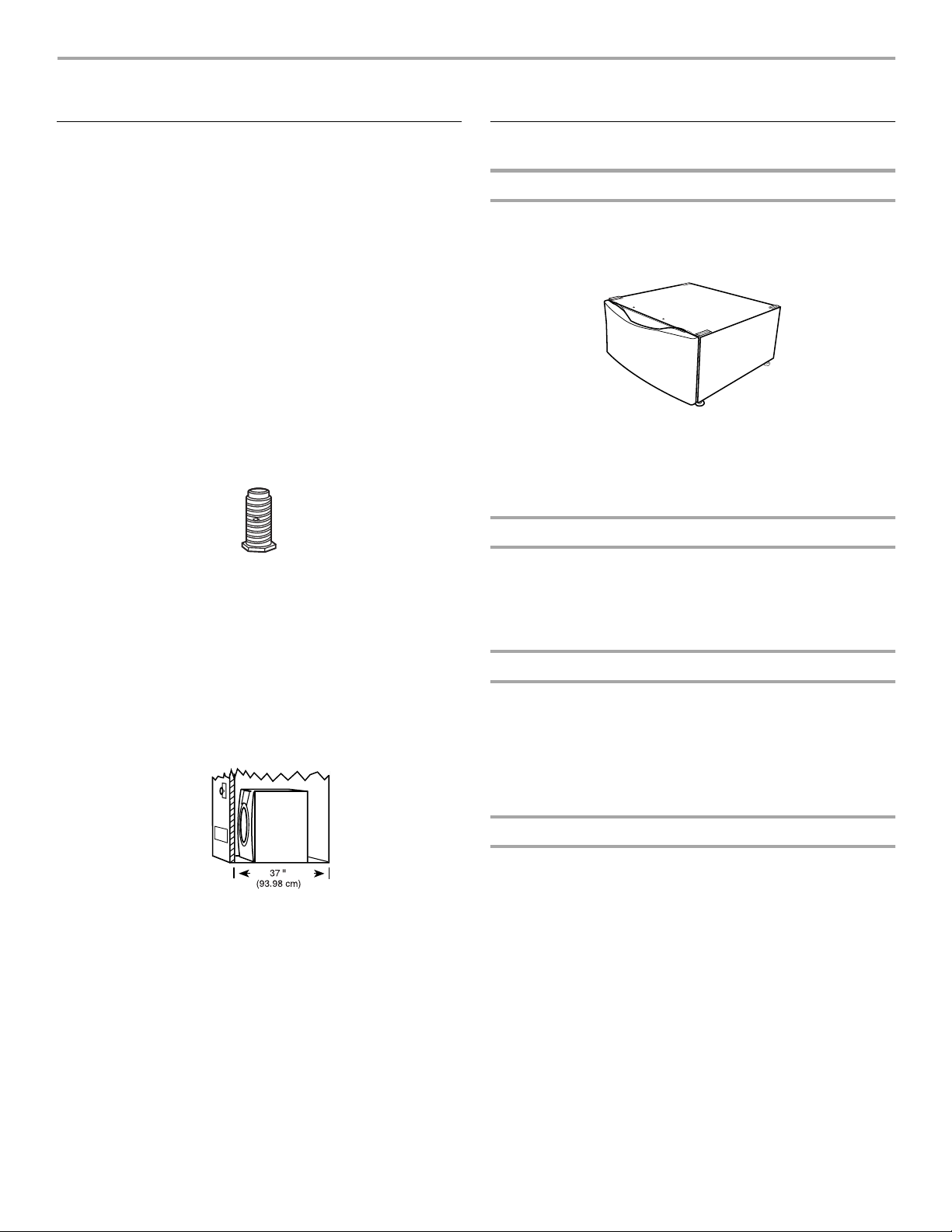
4 Leveling legs
Do not use leveling legs if installing the dryer on a
NOTE:
pedestal.
Parts needed
Check local codes. Check existing electrical supply and venting.
See “Electrical Requirements” and “Venting Requirements”
before purchasing parts.
■
For close-clearance installations between 31.5 in. (80.01 cm)
and 37 in. (93.98 cm), see “Plan Vent System” section for
venting requirements.
■
Safety glasses
■
Vent clamps
■
Caulking gun and
compound (for installing
new exhaust vent)
■
Gloves
■
Tin snips (new vent
installations)
■
¼ in. nut driver
Options
Pedestal
Are you placing the dryer on a pedestal? You may purchase a
pedestal separately for this dryer. This pedestal will add about
13 in. (33 cm) to the height of your unit for a total height of
approximately 51 in. (130 cm).
Optional pedestal
To order, call the dealer from whom you purchased your dryer or
refer to the “Assistance or Service” section of this manual. Ask
for Part Number LAB2700LQ (White), LAB2700LT (Biscuit) or
LAB2700LL (Pewter).
Stack Kit
Are you planning to stack your DUET® washer and dryer? To do
so, you will need to purchase a Stack Kit.
To order, call the dealer from whom you purchased your dryer or
refer to the “Assistance or Service” section of this manual. Ask
for Part Number 8541503.
Door Reversal Kit
Are you planning to reverse the door swing direction on your
®
dryer? To do so, you will need to purchase a Door
DUET
Reversal Kit.
To order, call the dealer from whom you purchased your dryer or
refer to the “Assistance or Service” section of this manual. Ask
for Part Number 3979303 (Shield Blue), 3979304 (Shield
Platinum), 3979770 (Biscuit Dark) or 3988097 (Whistler Grey).
Mobile home installations require metal exhaust system hardware
available for purchase from the dealer from whom you purchased
your dryer. For further information, please refer to the “Assistance
or Service” section of this manual.
4
Door Reversal and Stack Combination Kit
Are you planning to reverse the door swing direction on your
®
DUET
dryer and stack your DUET® washer and dryer? To do so,
you can purchase a Door Reversal and Stack Combination Kit.
To order, call the dealer from whom you purchased your dryer or
refer to the “Assistance and Service” section of this manual. Ask
for Part Number 8559215 (Shield Blue), 8559216 (Shield
Platinum), 8559217 (Biscuit Dark) or 8559218 (Whistler Grey).
Page 5
Location Requirements
Explosion Hazard
Keep flammable materials and vapors, such as
gasoline, away from dryer.
Place dryer at least 18 inches (46 cm) above the
floor for a garage installation.
Failure to do so can result in death, explosion,
or fire.
You will need
■
A location that allows for proper exhaust installation. See
“Venting Requirements.”
■
A separate 30 amp circuit.
■
A grounded electrical outlet located within 2 ft (61 cm) of
either side of the dryer. See “Electrical Requirements.”
■
A sturdy floor to support the total dryer weight of 200 lbs
(90.7 kg). The combined weight of a companion appliance
should also be considered.
■
A level floor with a maximum slope of 1 in. (2.5 cm) under
entire dryer. If slope is greater than 1 in. (2.5 cm), install
Extended Dryer Feet Kit, Part Number 279810. Clothes may
not tumble properly and automatic sensor cycles may not
operate correctly if dryer is not level.
■
For a garage installation, you will need to place the dryer at
least 18 in. (46 cm) above the floor. If using a pedestal, you
will need an additional 6 in. (15.24 cm).
Do not operate your dryer at temperatures below 45ºF (7ºC). At
lower temperatures, the dryer might not shut off at the end of an
automatic cycle. This can result in longer drying times.
The dryer must not be installed or stored in an area where it will
be exposed to water and/or weather.
Check code requirements. Some codes limit, or do not permit,
installation of the dryer in garages, closets, mobile homes, or
sleeping quarters. Contact your local building inspector.
Installation clearances
■
The location must be large enough to fully open the dryer
door.
■
Additional spacing should be considered for ease of
installation and servicing.
■
Additional clearances might be required for wall, door and
floor moldings.
■
Additional spacing of 1 in. (2.5 cm) on all sides of the dryer is
recommended to reduce noise transfer.
■
Companion appliance spacing should also be considered.
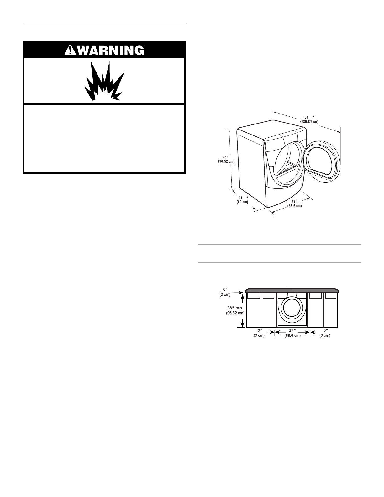
Dryer Dimensions
½
½
*
*Most installations require a minimum 5½ in. (14 cm) clearance
behind the dryer for the exhaust vent with elbow. See “Venting
Requirements.”
Minimum installation spacing for custom undercounter
installation
The dimensions shown are for the minimum spacing allowed.
Custom undercounter installation - Dryer only
5
Page 6
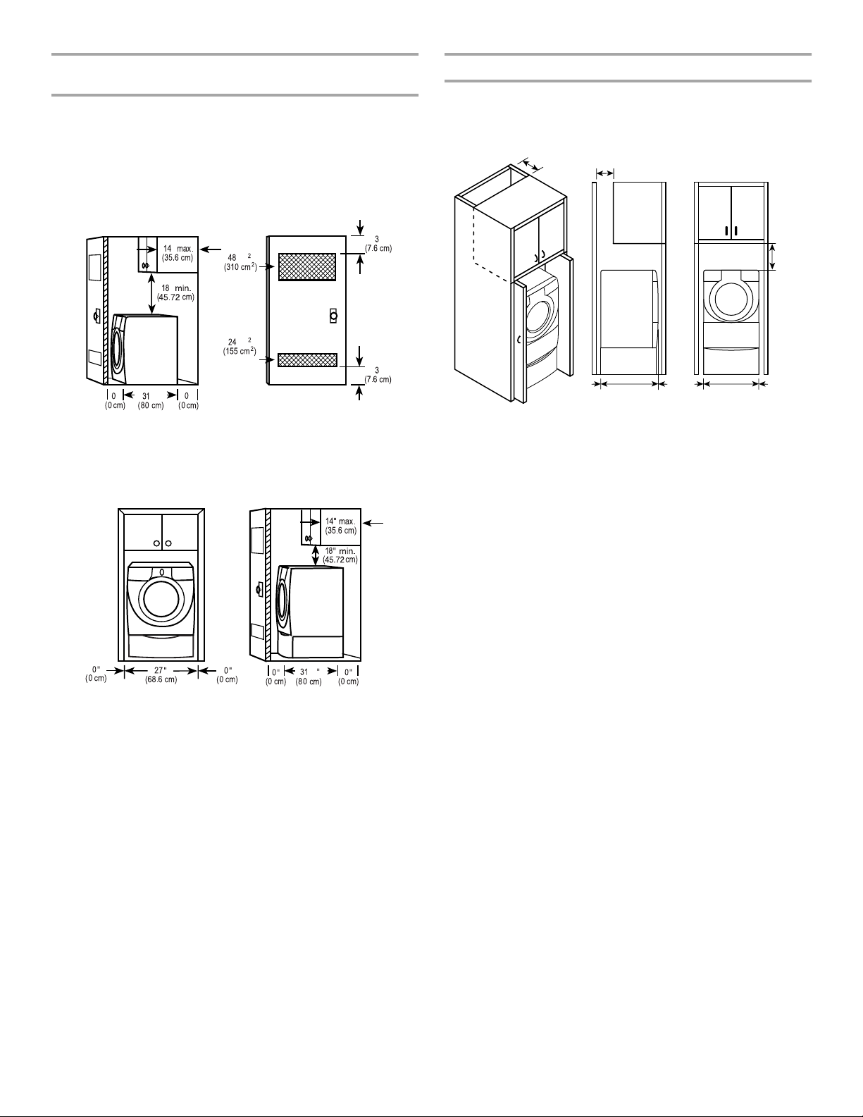
Minimum installation spacing for recessed or closet
installation, with or without a pedestal
■
The dimensions shown are for the minimum spacing allowed.
■
For closet installation, with a door, minimum ventilation
openings in the top and bottom of the door are required.
Louvered doors with equivalent ventilation openings are
acceptable.
Closet installation - Dryer only
Minimum installation spacing for cabinet installation
■
The dimensions shown are for the minimum spacing allowed.
■
For cabinet installation, with a door, minimum ventilation
openings in the top of the cabinet are required.
7" (17.8 cm)
7" (17.8 cm)
"
"
"
"
"
½
1
1. Side view - closet or confined area
2. Closet door with vents
in.
in.
2
Recessed or closet installation - Dryer on pedestal
"
"
0"
(0 cm)
31¹₂"
(80.0 cm)
0"
(0 cm)0"(0 cm)
27"
(68.6 cm)
0"
(0 cm)
9"
(22.9 cm)
Mobile home - Additional installation requirements
This dryer is suitable for mobile home installations. The installation must conform to the Manufactured Home Construction and
Safety Standard, Title 24 CFR, Part 3280 (formerly the Federal
Standard for Mobile Home Construction and Safety, Title 24,
HUD Part 280) or Standard CAN/CSA-Z240 MH.
Mobile home installations require:
■
Metal exhaust system hardware which is available for
purchase from your dealer.
■
Special provisions must be made in mobile homes to
introduce outside air into the dryer. The opening (such as a
nearby window) should be at least twice as large as the dryer
exhaust opening.
½
12
1. Recessed area
2. Side view - closet or confined area
6
Page 7
Electrical Requirements
It is your responsibility
■
To contact a qualified electrical installer.
■
To be sure that the electrical connection is adequate and in
conformance with the National Electrical Code, ANSI/NFPA
70-latest edition and all local codes and ordinances.
The National Electric Code requires a 4-wire supply
connection for homes built after 1996, dryer circuits involved
in remodeling after 1996, and all mobile home installations.
A copy of the above code standards can be obtained from:
National Fire Protection Association, One Batterymarch Park,
Quincy, MA 02269.
■
To supply the required 3 or 4 wire, single phase, 120/240-volt,
60-Hz., AC-only electrical supply (or 3 or 4 wire, 120/208-volt
electrical supply, if specified on the serial/rating plate) on a
separate 30-amp circuit, fused on both sides of the line. A
time-delay fuse or circuit breaker is recommended. Connect
to an individual branch circuit. Do not have a fuse in the
neutral or grounding circuit.
■
Do not use an extension cord.
■
If codes permit and a separate ground wire is used, it is
recommended that a qualified electrician determine that the
ground path is adequate.
Electrical Connection
To properly install your dryer, you must determine the type of
electrical connection you will be using and follow the instructions
provided for it here.
■
This dryer is manufactured ready to install with a 3-wire
electrical supply connection. The green cabinet-grounding
conductor is permanently connected to the neutral conductor
(white wire) within the dryer. If the dryer is installed with a
4-wire electrical supply connection, the green cabinetgrounding conductor must be removed from the external
ground conductor screw (green screw), and secured under
the neutral terminal (center or white wire) of the terminal
block. When the green cabinet-grounding conductor is
secured under the neutral terminal (center or white wire) of
the terminal block, the dryer cabinet is isolated from the
neutral conductor.
■
If local codes do not permit the connection of a cabinet
ground connector to the neutral wire, see “Optional 3-wire
connection” section.
■
Use a 4-wire conductor cord when the dryer is installed in a
mobile home or an area where local codes do not permit
grounding through the neutral.
If using a power supply cord:
Use a UL approved power supply cord kit marked for use with
clothes dryers. The kit should contain:
■
A UL approved 30 amp power supply cord, rated
120/240-volt minimum. The cord should be type SRD or
SRDT and be at least 4 ft (1.22 m) long. The wires that
connect to the dryer must end in ring terminals or spade
terminals with upturned ends.
■
A UL approved strain relief.
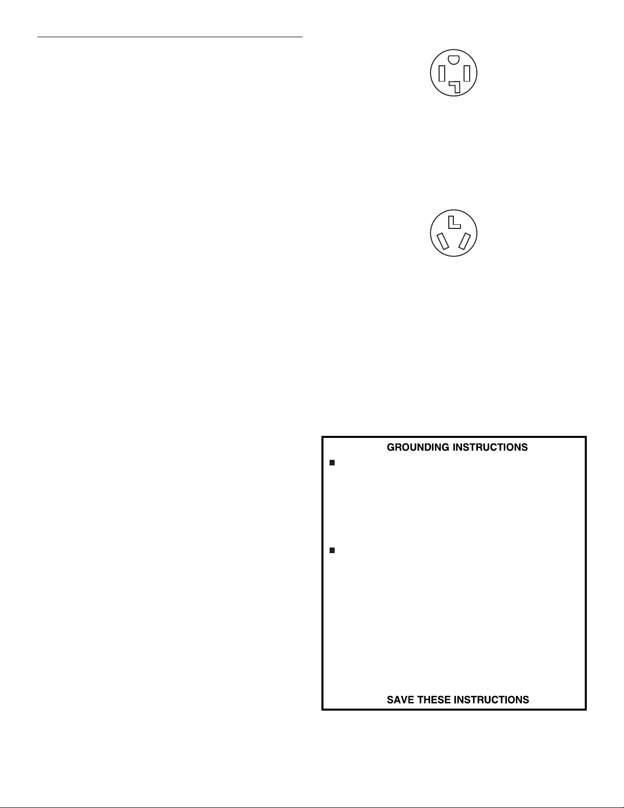
If your outlet looks like this:
4-wire receptacle (14-30R)
Then choose a 4-wire power supply cord with ring or spade
terminals and UL approved strain relief. The 4-wire power supply
cord, at least 4 ft (1.22 m) long, must have 4, 10-gauge solid
copper wires and match a 4-wire receptacle of NEMA Type
14-30R. The ground wire (ground conductor) may be either green
or bare. The neutral conductor must be identified by a white
cover.
If your outlet looks like this:
3-wire receptacle (10-30R)
Then choose a 3-wire power supply cord with ring or spade
terminals and UL approved strain relief. The 3-wire power supply
cord, at least 4 ft (1.22 m) long, must have 3, 10-gauge solid
copper wires and match a 3-wire receptacle of NEMA Type 1030R.
If connecting by direct wire:
Power supply cable must match power supply (4-wire or 3-wire)
and be:
■
Flexible armored cable or nonmetallic sheathed copper cable
(with ground wire), protected with flexible metallic conduit. All
current-carrying wires must be insulated.
■
10-gauge solid copper wire (do not use aluminum).
■
At least 5 ft (1.52 m) long.
For a grounded, cord-connected dryer:
This dryer must be grounded. In the event of malfunction
or breakdown, grounding will reduce the risk of electric shock
by providing a path of least resistance for electric current. This
dryer uses a cord having an equipment-grounding
conductor and a grounding plug. The plug must be plugged
into an appropriate outlet that is properly installed and
grounded in accordance with all local codes and ordinances.
For a permanently connected dryer:
This dryer must be connected to a grounded metal, permanent
wiring system, or an equipment-grounding conductor must be
run with the circuit conductors and connected to the
equipment-grounding terminal or lead on the dryer.
WARNING: Improper connection of the equipment-
grounding conductor can result in a risk of electric shock.
Check with a qualified electrician or service representative or
personnel if you are in doubt as to whether the dryer is
properly grounded. Do not modify the plug on the power
supply cord: if it will not fit the outlet, have a proper outlet
installed by a qualified electrician.
7
Page 8
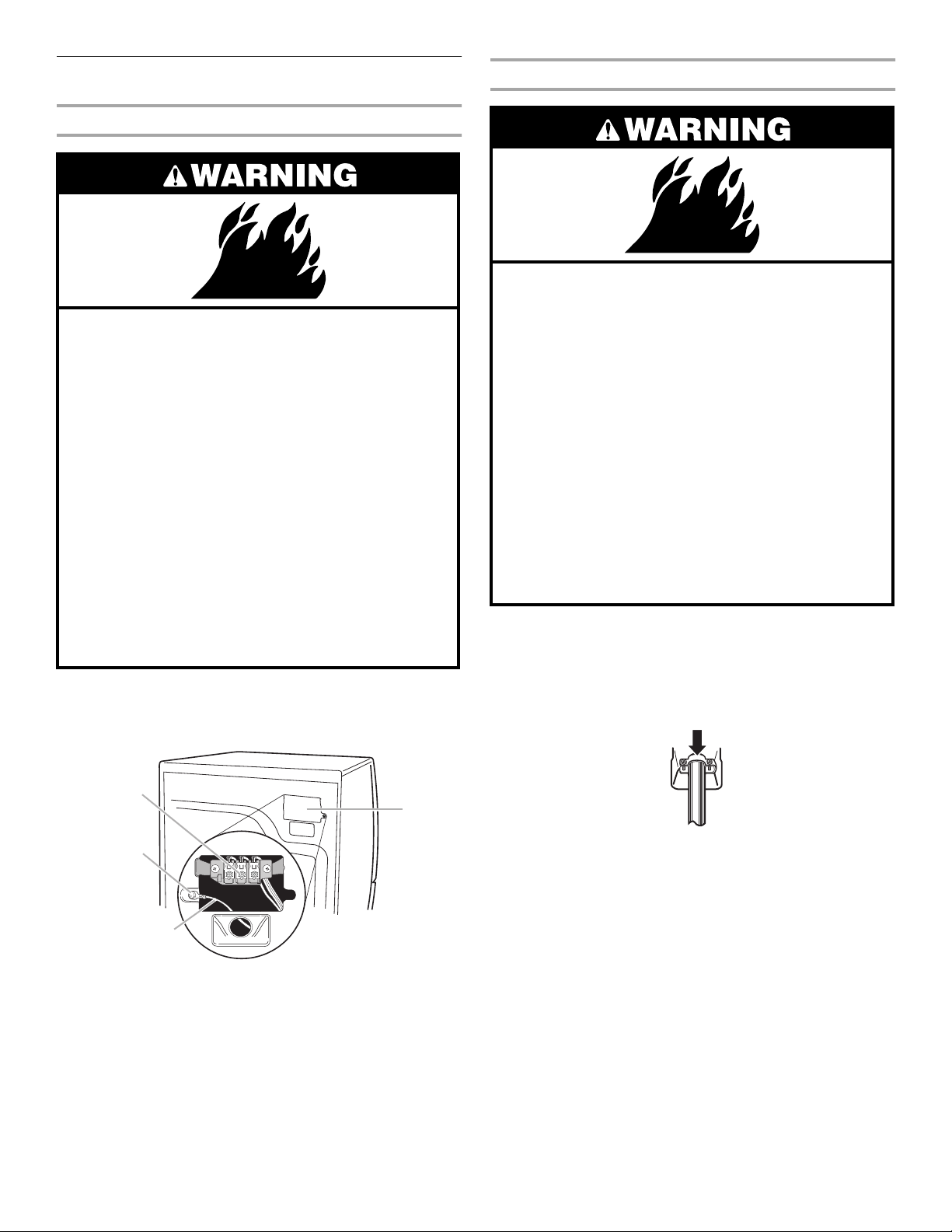
Electrical Connection
Power Supply Cord
Fire Hazard
Use a new UL listed 30 amp power
supply cord.
Use a UL listed strain relief.
Disconnect power before making electrical
connections.
Connect neutral wire (white or center wire) to
center terminal (silver).
Ground wire (green or bare wire) must be
connected to green ground connector.
Connect remaining 2 supply wires to remaining
2 terminals (gold).
Securely tighten all electrical connections.
Failure to do so can result in death, fire, or
electrical shock.
Disconnect power.
1.
Remove the hold-down screw and terminal block cover.
2.
Direct Wire
Fire Hazard
Use 10 gauge solid copper wire.
Use a UL listed strain relief.
Disconnect power before making electrical
connections.
Connect neutral wire (white or center wire) to
center terminal (silver).
Ground wire (green or bare wire) must be
connected to green ground connector.
Connect remaining 2 supply wires to remaining
2 terminals (gold).
Securely tighten all electrical connections.
Failure to do so can result in death, fire, or
electrical shock.
Assemble a
3.
on strain relief) into the hole below the terminal block
opening. Tighten strain relief screws just enough to hold the
two clamp sections together. Put power supply cord through
the strain relief. The strain relief should have a tight fit with the
dryer cabinet and be in a horizontal position.
³⁄₄
in. (1.9 cm) UL listed strain relief (UL marking
3
2
1
1. Neutral grounding wire (green/yellow)
2. External ground conductor screw
3. Center, silver-colored terminal block screw
4. Terminal block cover and hold-down screw
8
4
Now complete installation following instructions for your type
4.
of electrical connection:
4-wire (recommended)
3-wire (if 4-wire is not available)
Page 9
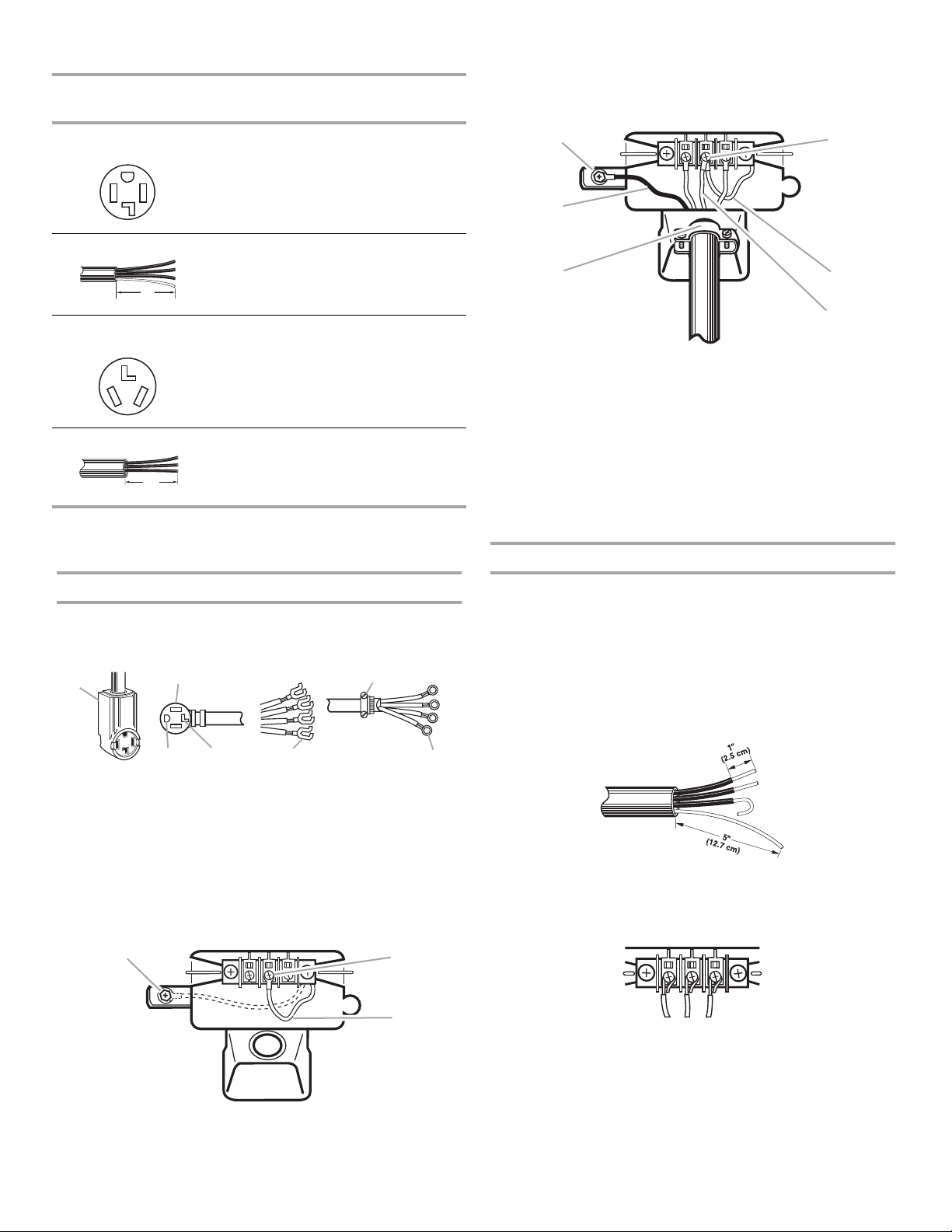
Electrical Connection Options
2
4
5
If your home has: And you will be
connecting to:
4-wire receptacle
(NEMA Type 14-30R)
A UL listed, 120/
240 volt
minimum, 30
amp, dryer
power supply
cord*
Go to Section
4-wire connection:
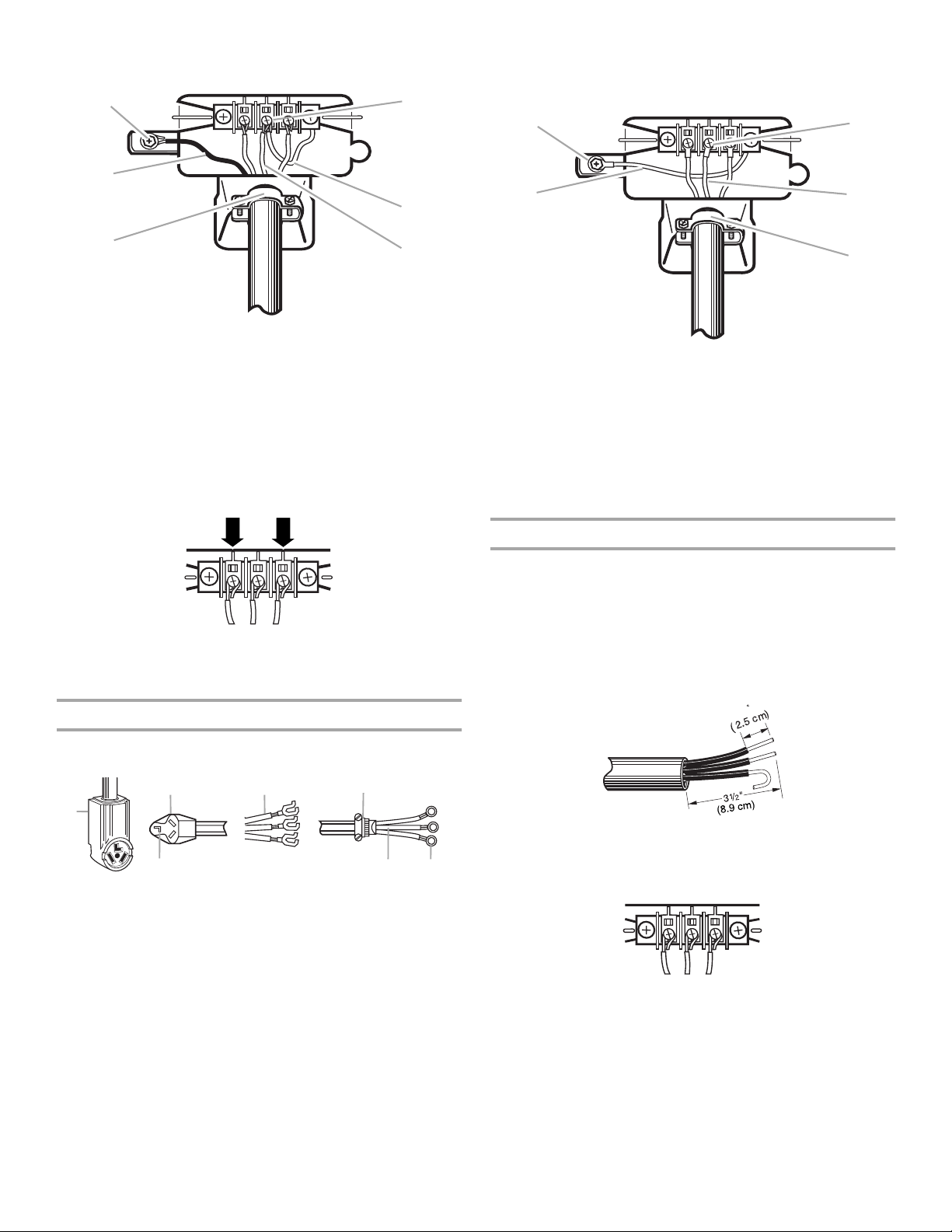
Power supply cord
Connect ground wire (green or bare) of power supply cord to
3.
external ground conductor screw. Tighten screw.
Connect neutral wire (white or center wire) of power supply
4.
cord under center screw of the terminal block.
1
2
4-wire direct A fused
disconnect or
5"
(12.7 cm)
3-wire receptacle
(NEMA type 10-30R)
circuit breaker
box*
A UL listed, 120/
240 volt
4-wire connection:
Direct Wire
3-wire connection:
Power supply cord
minimum, 30
amp., dryer
power supply
cord*
3-wire direct A fused
disconnect or
1
3 / "
(8.9 cm)
2
circuit breaker
box*
3-wire connection:
Direct Wire
*If local codes do not permit the connection of a frame-grounding
conductor to the neutral wire, go to “Optional
3-wire Connection” section.
4-wire connection: Power supply cord
IMPORTANT:
and where local codes do not permit the use of 3-wire
connections.
1
A 4-wire connection is required for mobile homes
2
6
3
6
1. External ground conductor screw
2. Green or bare copper wire of power supply cord
³⁄₄
in. (1.9 cm) UL listed strain relief
3.
4. Center silver-colored terminal block screw
5. Neutral grounding wire (green/yellow)
6. Neutral wire (white or center wire)
Connect the other wires to outer terminal block screws.
5.
Tighten screws.
Tighten strain relief screws.
6.
Insert tab of terminal block cover into slot of dryer rear panel.
7.
Secure cover with hold-down screw.
4-wire connection: Direct wire
IMPORTANT:
and where local codes do not permit the use of 3-wire
connections.
Direct wire cable must have 5 ft (1.52 m) of extra length so dryer
can be moved if needed.
Strip 5 in. (12.7 cm) of outer covering from end of cable, leaving
bare ground wire at 5 in. (12.7 cm). Cut 1
remaining wires. Strip insulation back 1 in. (2.5 cm). Shape ends
of wires into a hook shape.
A 4-wire connection is required for mobile homes
¹⁄₂
in. (3.8 cm) from 3
4
3
1. 4-wire receptacle (NEMA type 14-30R)
2. 4-prong plug
3. Ground prong
4. Neutral prong
5. Spade terminals with upturned ends
6. ¾ in. (1.9 cm) UL listed strain relief
7. Ring terminals
Remove center terminal block screw.
1.
Remove appliance ground wire (green with yellow stripes)
2.
5
from external ground conductor screw. Fasten it under center,
silver-colored terminal block screw.
1
3
1. External ground conductor screw - Dotted line
shows position of NEUTRAL ground wirebefore
being moved to center terminalblock screw
2. Center silver-colored terminal block screw
3. Green/yellow wire of harness
7
When connecting to the terminal block, place the hooked end of
the wire under the screw of the terminal block (hook facing right),
squeeze hooked end together and tighten screw. See example
below.
Remove center terminal block screw.
1.
Remove appliance ground wire (green with yellow stripes)
2.
from external ground conductor screw. Fasten it under center,
silver-colored terminal block screw.
9
Page 10
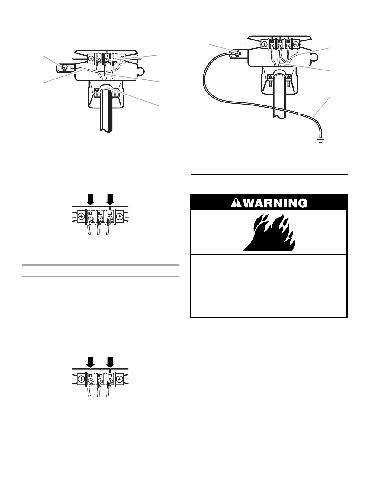
Connect ground wire (green or bare) of power supply cable to
4
5
1
2
3
4
5
1
3.
external ground conductor screw. Tighten screw.
1
2
Connect neutral wire (white or center wire) of power supply
2.
cord to the center, silver-colored terminal screw of the
terminal block. Tighten screw.
3
1. External ground conductor screw
2. Green or bare copper wire of power supply cord
³⁄₄
in. (1.9 cm) UL listed strain relief
3.
4. Center silver-colored terminal block screw
5. Neutral grounding wire (green/yellow)
6. Neutral wire (white or center wire)
Place the hooked end of the neutral wire (white wire) of power
4.
supply cable under the center screw of terminal block (hook
facing right). Squeeze hooked end together. Tighten screw.
Place the hooked ends of the other power supply cable wires
5.
under the outer terminal block screws (hooks facing right).
Squeeze hooked ends together. Tighten screws.
Tighten strain relief screws.
6.
Insert tab of terminal block cover into slot of dryer rear panel.
7.
Secure cover with hold-down screw.
6
1. External ground conductor screw
2. Neutral grounding wire (green/yellow)
3. Center silver-colored terminal block screw
4. Neutral wire (white or center wire)
³⁄₄
in. (1.9 cm) UL listed strain relief
5.
Connect the other wires to outer terminal block screws.
3.
Tighten screws.
Tighten strain relief screws.
4.
Insert tab of terminal block cover into slot of dryer rear panel.
5.
Secure cover with hold-down screw.
3-wire connection: Direct wire
Use where local codes permit connecting cabinet-ground
conductor to neutral wire.
Direct wire cable must have 5 ft (1.52 m) of extra length so dryer
can be moved if needed.
¹⁄₂
Strip 3
insulation back 1 in. (2.5 cm). If using 3-wire cable with ground
wire, cut bare wire even with outer covering. Shape ends of wires
into a hook shape.
in. (8.9 cm) of outer covering from end of cable. Strip
3-wire connection: Power supply cord
Use where local codes permit connecting cabinet-ground
conductor to neutral wire.
2
4
5
1
When connecting to the terminal block, place the hooked end of
the wire under the screw of the terminal block (hook facing right),
6
3
1. 3-wire receptacle (NEMA type 10-30R)
2. 3-wire plug
3. Neutral prong
4. Spade terminals with up turned ends
³⁄₄
in. (1.9 cm) UL listed strain relief
5.
6. Ring terminals
7. Neutral (white or center wire)
Loosen or remove center terminal block screw.
1.
7
squeeze hooked end together and tighten screw. See example
below.
Loosen or remove center terminal block screw.
1.
10
Page 11
Place the hooked end of the neutral wire (white or center wire)
4
3
5
1
2
3
4
2.
of power supply cable under the center screw of terminal
block (hook facing right). Squeeze hooked end together.
Tighten screw.
1
2
1. External ground conductor screw
2. Neutral grounding wire (green/yellow)
3. Center silver-colored terminal block screw
4. Neutral wire (white or center wire)
³⁄₄
in. (1.9 cm) UL listed strain relief
5.
Place the hooked ends of the other power supply cable wires
3.
under the outer terminal block screws (hooks facing right).
Squeeze hooked ends together. Tighten screws.
Connect a separate copper ground wire from the external
6.
ground conductor screw to an adequate ground.
1. External ground conductor screw
2. Neutral grounding wire (green/yellow)
3. Neutral wire (white or center wire)
4. Grounding path determined by a qualified electrician
Venting Requirements
Tighten strain relief screws.
4.
Insert tab of terminal block cover into slot of dryer rear panel.
5.
Secure cover with hold-down screw.
Optional 3-wire connection
Use for direct wire or power supply cord where local codes
do not permit connecting cabinet-ground conductor to
neutral wire.
Remove center terminal block screw.
1.
Remove appliance ground wire (green with yellow stripes)
2.
from external ground conductor screw. Connect appliance
ground wire and the neutral wire (white or center wire) of
power supply cord/cable under center, silver-colored terminal
block screw. Tighten screw.
Connect the other wires to outer terminal block screws.
3.
Tighten screws.
Tighten strain relief screws.
4.
Insert tab of terminal block cover into slot of dryer rear panel.
5.
Secure cover with hold-down screw.
Use a heavy metal vent.
Do not use a plastic vent.
Do not use a metal foil vent.
Failure to follow these instructions can result in
death or fire.
WARNING:
EXHAUSTED OUTDOORS.
4 in. (10.2 cm) heavy metal exhaust vent and clamps must be
used. DURASAFE™ vent products are recommended.
DURASAFE™ vent products can be purchased from your dealer
or by calling Whirlpool Parts and Accessories. For more
information, see the “Assistance or Service” section of this
manual.
■
The dryer exhaust must not be connected into any gas vent,
chimney, wall, ceiling, or a concealed space of a building.
■
Do not use an exhaust hood with a magnetic latch.
■
Do not install flexible metal vent in enclosed walls, ceilings or
floors.
To reduce the risk of fire, this dryer MUST BE
Fire Hazard
11
Page 12
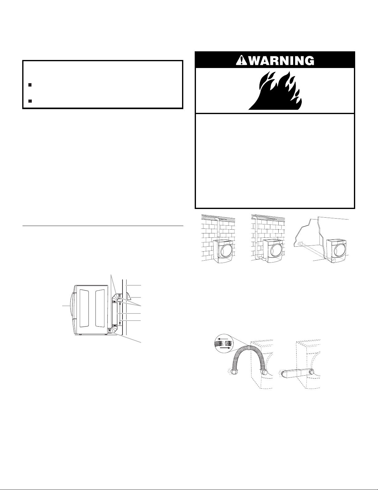
■
8
5
4
3
1
2
3
Use clamps to seal all joints. Exhaust vent must not be
connected or secured with screws or other fastening devices
which extend into the interior of the duct. Do not use duct
tape.
IMPORTANT:
Improper venting can cause moisture and lint to collect
indoors, which may result in:
Moisture damage to woodwork, furniture, paint, wall-
paper, carpets, etc.
Housecleaning problems and health problems.
Observe all governing codes and ordinances.
Optional exhaust installations
This dryer can be converted to exhaust out the right side, left
side, or through the bottom. Contact your local dealer to have the
dryer converted.
Use a heavy metal vent. Do not use plastic or metal foil vent.
Rigid metal vent is recommended to prevent crushing and
kinking.
Flexible metal vent must be fully extended and supported when
the dryer is in its final position. Remove excess flexible metal vent
to avoid sagging and kinking that can result in reduced airflow
and poor performance.
An exhaust hood should cap the vent to prevent rodents and
insects from entering the home.
Exhaust hood must be at least 12 in. (30.5 cm) from the ground or
any object that is in the path of the exhaust (such as flowers,
rocks or bushes, etc.).
If using an existing vent system, clean lint from the entire length
of the system and make sure exhaust hood is not plugged with
lint. Replace any plastic or metal foil vent with rigid metal or
flexible metal vent.
Plan Vent System
Typical exhaust installations
Typical installations vent the dryer from the rear of the dryer.
Other installations are possible.
2
Fire Hazard
Cover unused exhaust holes with one of the
following kits:
279818 (white)
279925 (biscuit)
279969 (pewter)
Contact your local dealer.
Failure to follow these instructions can result in
death, fire, electrical shock, or serious injury.
1. Standard rear offset exhaust installation
2. Left or right side exhaust installation
3. Bottom exhaust installation (Not an option
with pedestal installations.)
1
1. Dryer
2. Elbow
3. Wall
4. Exhaust hood
5. Clamps
6. Rigid metal or flexible metal vent
7. Vent length necessary to connect
elbows
8. Exhaust outlet
6
7
Alternate installations for close clearances
Venting systems come in many varieties. Select the type best for
your installation. Two close-clearance installations are shown.
Refer to the manufacturer’s instructions.
12
1. Over the top installation (also available
with one offset elbow)
2. Periscope installation
12
Page 13
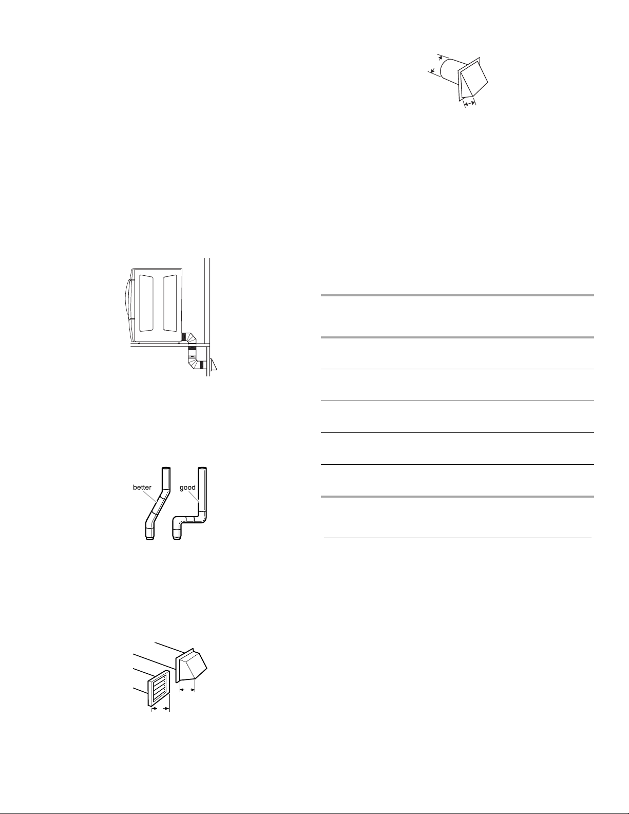
The following kits for close clearance alternate
4"
(10.2 cm)
2½"
(6.4 cm)
NOTE:
installations are available for purchase. Please see the
“Assistance or Service” section of this manual to order.
■
Over the top Installation:
Part Number 4396028
■
Periscope Installation (For use with dryer vent to wall vent
mismatch):
Part Number 4396037 - 0 in. (0 cm) to 18 in. (45.72 cm)
mismatch
Part Number 4396011 - 18 in. (45.72 cm) to 29 in. (73.66 cm)
mismatch
Part Number 4396014 - 29 in. (73.66 cm) to 50 in. (127 cm)
mismatch
Special provisions for mobile home installations
The exhaust vent must be securely fastened to a noncombustible
portion of the mobile home structure and must not terminate
beneath the mobile home. Terminate the exhaust vent outside.
The angled hood style (shown following) is acceptable.
See the exhaust vent length chart that matches your hood
type for the maximum vent lengths you can use.
Exhaust systems longer than specified will:
■
Shorten the life of the dryer.
■
Reduce performance, resulting in longer drying times and
increased energy usage.
Determine the number of elbows you will need.
3.
IMPORTANT:
Do not use vent runs longer than those
specified in the Vent Length Chart.
The following chart helps you determine your maximum vent
length based on the number of 90° turns or elbows you will
need and the type of vent (rigid or flexible metal) and hood
that you will use.
Vent Length Chart
Determine Vent Length
Select the route that will provide the straightest and most
1.
direct path outdoors. Plan the installation to use the fewest
number of elbows and turns. When using elbows or making
turns, allow as much room as possible. Bend vent gradually
to avoid kinking. Avoid 90º turns.
Determine vent length.
2.
The maximum length of the exhaust system depends upon:
■
The type of vent (rigid metal or flexible metal).
■
The number of elbows used.
■
Type of hood.
Recommended hood styles are shown here.
2
1
4"
(10.2 cm)
4"
(10.2 cm)
1. Louvered hood style
2. Box hood style
Number of
90º turns
or elbows
0Rigid metal
1Rigid metal
2Rigid metal
3Rigid metal
4Rigid metal
Side and bottom exhaust installations have a 90º turn
NOTE:
Type of
vent
Flexible metal
Flexible metal
Flexible metal
Flexible metal
Flexible metal
Box or
Louvered
hoods
64 ft (20 m)
36 ft (11 m)
54 ft (16.5 m)
31 ft (9.4 m)
44 ft (13.4 m)
27 ft (8.2 m)
35 ft (10.7 m)
25 ft (7.6 m)
27 ft (8.2 m)
23 ft (7 m)
Angled
hoods
58 ft (17.7 m)
28 ft (8.5 m)
48 ft (14.6 m)
23 ft (7 m)
38 ft (11.6 m)
19 ft (5.8 m)
29 ft (8.8 m)
17 ft (5.2 m)
21 ft (6.4 m)
15 ft (4.6 m)
inside the dryer. To determine maximum exhaust length, add one
90º turn to the chart.
Install Vent System
(Optional) Put on safety glasses and gloves.
1.
Install exhaust hood. Use caulking compound to seal exterior
2.
wall opening around exhaust hood.
Connect vent to exhaust hood. Vent must fit inside exhaust
3.
hood. Secure vent to exhaust hood with 4 in. (10.2 cm)
clamp.
Run vent to dryer location. Use the straightest path possible.
4.
See “Determine Vent Length.” Avoid 90º turns. Use clamps to
seal all joints. Do not use duct tape, screws or other fastening
devices that extend into the interior of the vent to secure
vent.
13
Page 14
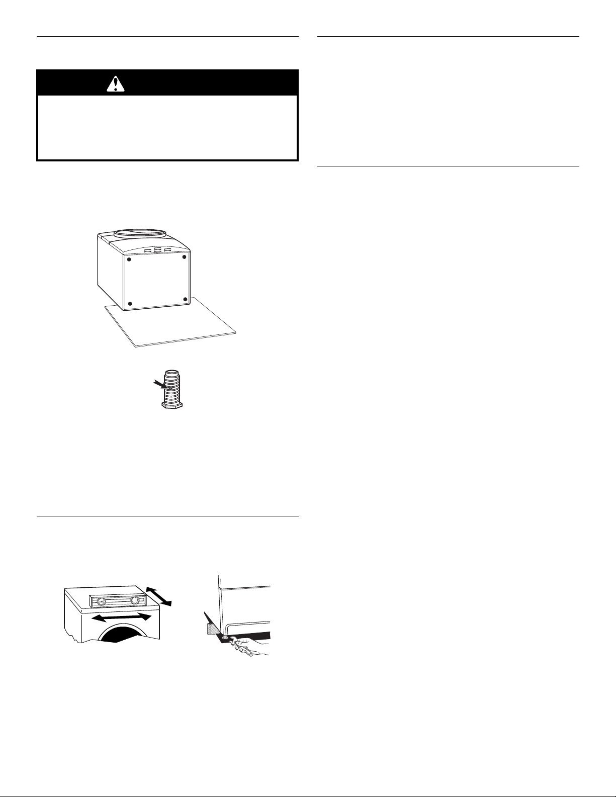
Install Leveling Legs
WARNING
Excessive Weight Hazard
Use two or more people to move and install
dryer.
Failure to do so can result in back or other injury.
To protect the floor, use a large flat piece of cardboard from
1.
the dryer carton. Place cardboard under the entire back edge
of the dryer. See illustration.
Firmly grasp the body of the dryer (not the console panel).
2.
Gently lay the dryer on the cardboard.
Examine the leveling legs. Find the diamond marking.
3.
Screw the legs into the leg holes by hand. Use a wrench to
4.
finish turning the legs until the diamond marking is no longer
visible.
Place a carton corner post under each of the 2 dryer back
5.
corners. Stand the dryer up. Slide the dryer on the corner
posts until it is close to its final location. Leave enough room
to connect the exhaust vent.
Once connection is made and dryer is in final location,
6.
remove corner posts and cardboard.
Level Dryer
Check the levelness of the dryer. Check levelness first
side to side, then front to back.
Connect Vent
Using a 4 in. (10.2 cm) clamp, connect vent to exhaust outlet
1.
in dryer. If connecting to existing vent, make sure the vent is
clean. The dryer vent must fit over the dryer exhaust outlet
and inside the exhaust hood. Make sure the vent is secured
to exhaust hood with a 4 in. (10.2 cm) clamp.
Move dryer into final position. Do not crush or kink vent.
2.
Make sure dryer is level.
(On gas models) Check to be sure there are no kinks in the
3.
flexible gas line.
Complete Installation
Check to be sure all parts are now installed. If there is an
1.
extra part, go back through the steps to see which step was
skipped.
Check to be sure you have all of your tools.
2.
Dispose of all packaging materials.
3.
Check the dryer’s final location. Be sure the vent is not
4.
crushed or kinked.
Check to be sure the dryer is level. See “Level Dryer.”
5.
Plug into a grounded outlet. Turn power on.
6.
Remove the blue protective film on the console and any tape
7.
remaining on the dryer.
Read “Dryer Use.”
8.
Wipe the dryer drum interior thoroughly with a damp cloth to
9.
remove any dust.
Set the dryer on a full heat cycle (not an air cycle) for
10.
20 minutes and start the dryer.
If the dryer will not start, check the following:
■
Controls are set in a running or “On” position.
■
Start button has been pushed firmly.
■
Dryer is plugged into a grounded outlet.
■
Electrical supply is connected.
■
House fuse is intact and tight, or circuit breaker has not
tripped.
■
Dryer door is closed.
When the dryer has been running for 5 minutes, open the
11.
dryer door and feel for heat.
If you do not feel heat, turn the dryer off and check the
following:
■
There may be 2 fuses or circuit breakers for the dryer. Check
to make sure both fuses are intact and tight, or that both
circuit breakers have not tripped. If there is still no heat,
contact a qualified technician.
You may notice a burning odor when the dryer is first
NOTE:
heated. This odor is common when the heating element is first
used. The odor will go away.
If the dryer is not level, prop up the dryer using a wood block.
Use a wrench to adjust the legs up or down and check again for
levelness.
It might be necessary to level the dryer again after it has
NOTE:
been moved into its final position.
14
Page 15
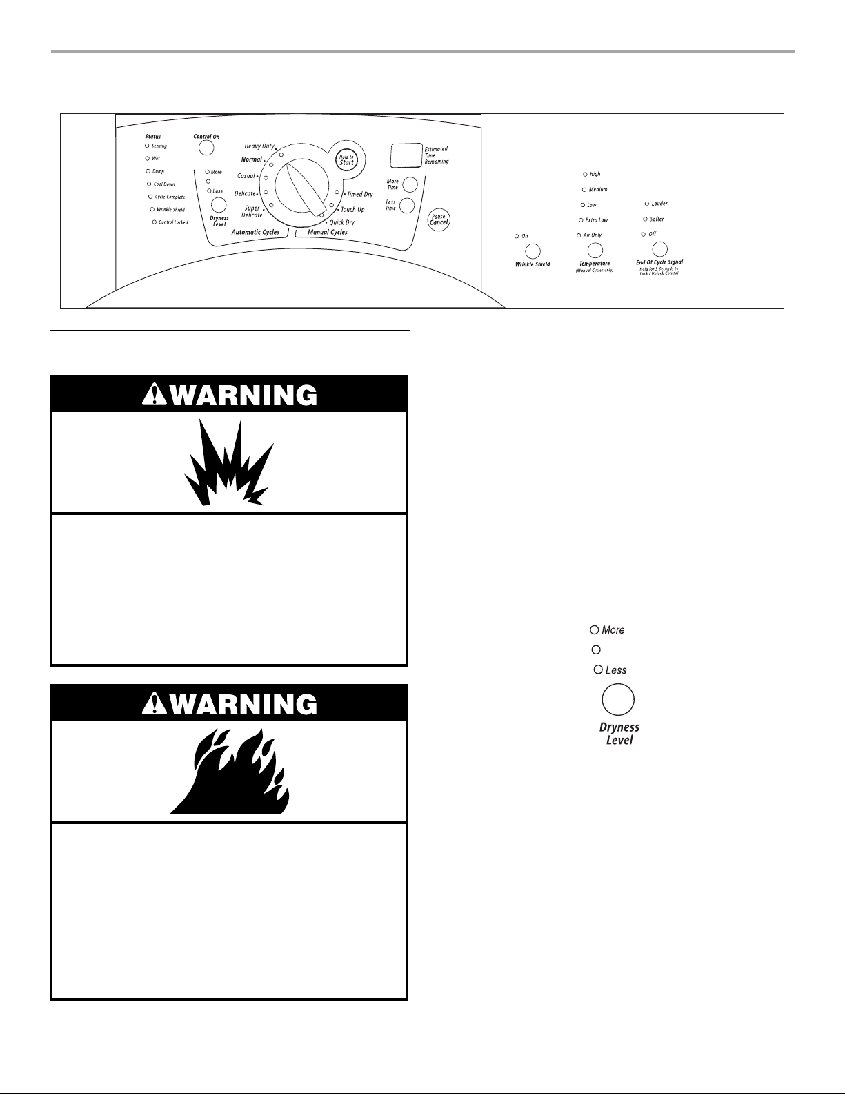
DRYER USE
Starting Your Dryer
Explosion Hazard
Keep flammable materials and vapors, such as
gasoline, away from dryer.
Do not dry anything that has ever had anything
flammable on it (even after washing).
Failure to follow these instructions can result in
death, explosion, or fire.
WARNING:
persons, read the IMPORTANT SAFETY INSTRUCTIONS before
operating this appliance.
The following is a guide to starting your dryer. Please refer to
specific sections of this manual for more detailed information.
Clean lint screen before or after each cycle. See “Cleaning
1.
the Lint Screen.”
Place laundry into dryer and shut door. See “Loading.”
2.
Rotate the dial to select either an Automatic or Manual Cycle
3.
then press the CONTROL ON button. The preset settings and
drying time for the cycle chosen will be displayed.
To use an Automatic Cycle
■
■
To reduce the risk of fire, electric shock, or injury to
Point the dial to an Automatic Cycle.
Select DRYNESS LEVEL to adjust how dry you want the
load to be. The time displayed is an estimated length of
the cycle based on the Dryness Level selected. As the
cycle runs, the control senses the dryness of the load and
adjusts the time automatically for the selected Dryness
Level.
Fire Hazard
No washer can completely remove oil.
Do not dry anything that has ever had any type of
oil on it (including cooking oils).
Items containing foam, rubber, or plastic must be
dried on a clothesline or by using an Air Cycle.
Failure to follow these instructions can result in
death or fire.
Time is not adjustable for Automatic Cycles. Pressing
NOTE:
the More Time or Less Time buttons will cause a triple beep,
indicating that the time cannot be changed.
■
Press the WRINKLE SHIELD™ feature button if this
option is desired.
■
Press the END OF CYCLE SIGNAL button to set signal
volume to desired level.
■
Press (and hold) HOLD TO START button until dryer starts
(about 1 second).
Once an Automatic cycle has started, the WRINKLE
SHIELD™ feature and the End of Cycle Signal level can be
adjusted. Press the PAUSE/CANCEL key twice to stop the
dryer and clear the settings, allowing you to select another
cycle and Dryness Level.
15
Page 16
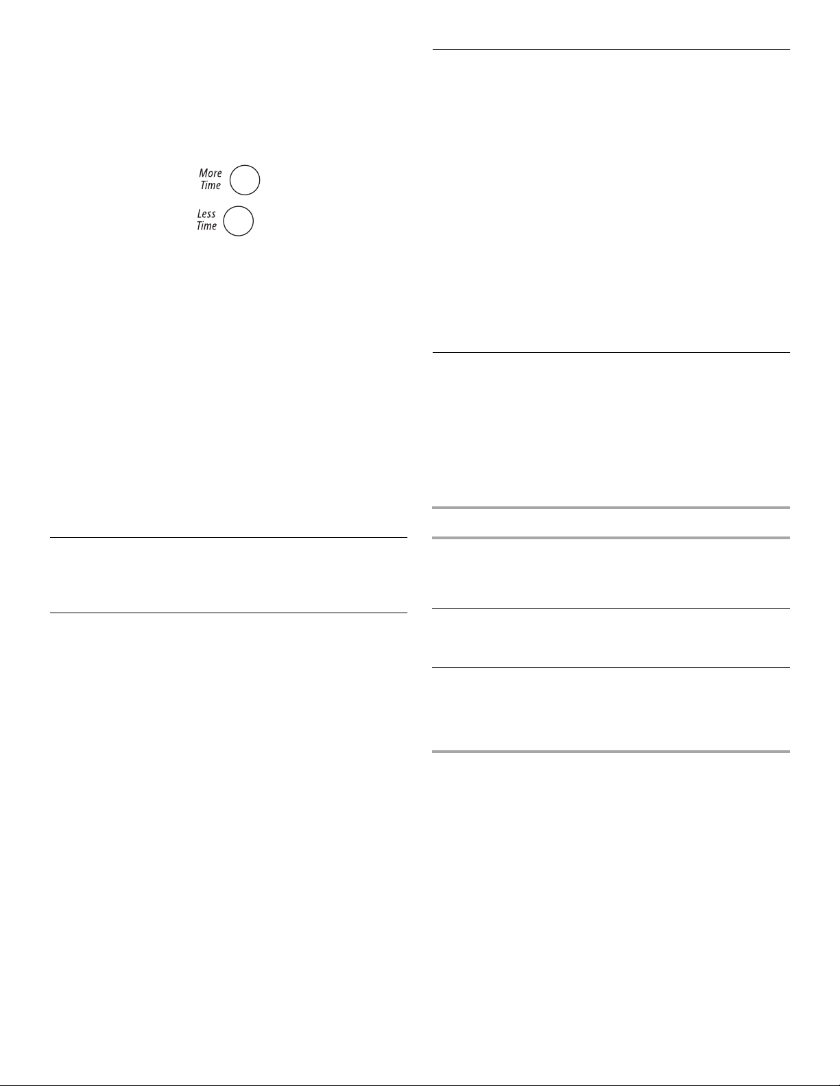
To use a Manual Cycle
■
Rotate the dial to select a Manual Cycle.
Press MORE TIME or LESS TIME until the desired drying time
is displayed. Tap MORE TIME or LESS TIME and the time will
change by 1-minute intervals. Press and hold MORE TIME or
LESS TIME and the time will change by 5-minute intervals.
The initial time displayed is the actual drying time.
The More Time or Less Time feature can be used only
NOTE:
with Manual Cycles.
■
Press TEMPERATURE until the desired temperature
glows.
Pressing the Dryness Level button will cause the triple
NOTE:
beep indicating that this option is not selectable. Also, a
Dryness Level is not indicated.
■
Press the WRINKLE SHIELD™ feature button if this
option is desired.
■
Press the END OF CYCLE SIGNAL button to set volume
to desired level.
■
Press (and hold) HOLD TO START button until dryer starts
(about 1 second).
While a Manual Cycle is running, you can change the settings
for Time, Temperature, the WRINKLE SHIELD™ feature, and
the End of Cycle Signal. Press the PAUSE/CANCEL key twice
to stop the dryer and clear the settings, allowing you to select
another cycle.
Control Locked
This feature allows you to lock your settings to prevent
unintended use of the dryer. You can also use the Control Locked
feature to prevent unintended cycle or option changes during
dryer operation.
To enable the Control Locked feature when dryer is
running:
Press and hold the END OF CYCLE SIGNAL button for
3 seconds. The control is locked when a single beep is heard and
the Control Locked status light is on.
■
When the dryer is off, it is not necessary to press the Control
On button before activating the Control Locked feature.
To unlock:
Press and hold the END OF CYCLE SIGNAL button for 3 seconds
to turn this feature off.
When the dryer is running and Control Locked is on, the
NOTE:
dryer can be stopped by pressing the Pause/Cancel button, but
can’t be restarted until the control is unlocked.
Loading
Properly loading your dryer can lower your utility bill and prolong
the life of your garments.
Loading suggestions
■
Load the dryer by the amount of space items take up, not by
their weight.
■
Do not overload the dryer. This causes wrinkling and uneven
drying.
Super Capacity Plus Dryers
Stopping Your Dryer
To stop your dryer at any time
Press PAUSE/CANCEL twice or open the door.
Pausing or Restarting
To pause the dryer at any time
Open the door or press PAUSE/CANCEL once.
To restart the dryer
Close the door and press (and hold) HOLD TO START button until
dryer starts.
: Drying will continue from where the cycle was interrupted
NOTE
if you close the door and press Start within 5 minutes. If the cycle
is interrupted for more than 5 minutes, the dryer will shut off.
Select new cycle settings before restarting the dryer.
Heavy Work Clothes
4 jeans
4 workpants
4 workshirts
Towels
10 bath towels
10 hand towels
Mixed Load
3 sheets (1 king, 2 twin)
4 pillowcases
3 shirts
3 blouses
2 sweatpants
2 sweatshirts
14 washcloths
9 T-shirts
9 shorts
10 handkerchiefs
16
Page 17
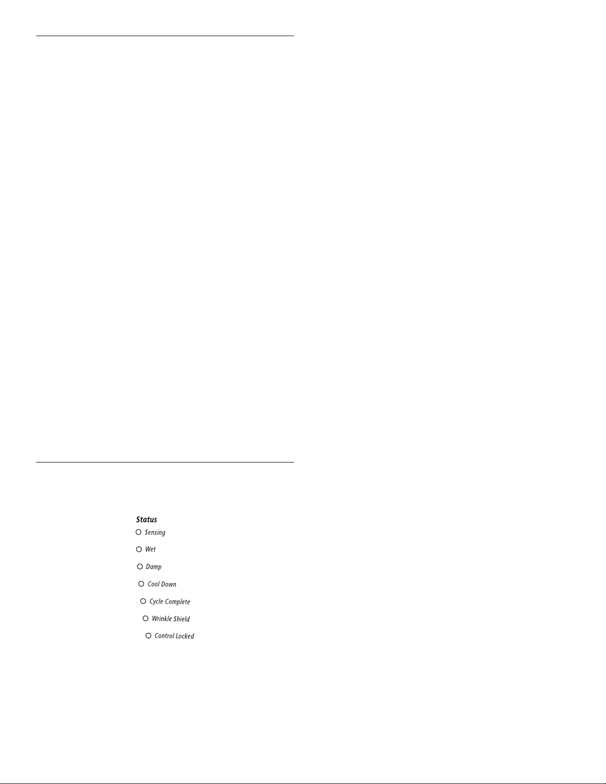
Drying and Cycle Tips
Select the correct cycle and dryness level or temperature for your
load. If an Automatic Cycle is running, the display shows the
estimated cycle time when your dryer is automatically sensing
the dryness level of your load. If a Manual Cycle is running, the
display shows the exact number of minutes remaining in the
cycle.
Cool Down tumbles the load without heat during the last few
minutes of all cycles. Cool Down makes the loads easier to
handle and reduces wrinkling. The length of the Cool Down
depends on the load size and dryness level.
Drying tips
■
Follow care label directions when they are available.
■
If desired, add a fabric softener sheet. Follow package
instructions.
■
Remove the load from the dryer as soon as tumbling stops to
reduce wrinkling. This is especially important for permanent
press, knits, and synthetic fabrics.
■
Avoid drying heavy work clothes with lighter fabrics. This
could cause overdrying of lighter fabrics, leading to increased
shrinkage or wrinkling.
Cycle tips
■
Dry most loads using the preset cycle settings.
■
Refer to the Automatic or Manual Preset Cycle Settings chart
(in the “Cycles” section) for a guide to drying various loads.
■
Drying temperature and Dryness Level are preset when
you choose an Automatic Cycle. You can choose a
different dryness level, depending on your load by
pressing the DRYNESS LEVEL button to select MORE or
LESS.
■
If you wish to adjust the cycle length of a Manual Cycle,
you must press MORE TIME or LESS TIME. Adjust the
temperature of a Manual Cycle by pressing
TEMPERATURE until the desired temperature is selected.
You cannot choose a Dryness Level with Manual
NOTE:
Cycles.
Sensing
When a cycle is first turned on, the SENSING light glows until a
wet item is detected.
■
In an Automatic Cycle, if a wet item has not been detected
within 10 minutes, the Sensing light will turn off and the dryer
will shut down.
■
In a Manual Cycle, if a wet item is not detected after
10 minutes the Wet light turns on and the selected cycle
continues.
Wet
The WET light will turn on when a wet item has been detected in
the dryer. The Wet light will remain on until:
■
The damp dry point is reached in an Automatic Cycle.
■
The dryer enters the cool down period in a Manual Cycle.
Damp
The DAMP light indicates that the load has reached the damp dry
level.
The Damp light is not used with manual cycles.
NOTE:
Cool Down
The COOL DOWN light glows during the cool down part of the
cycle. Laundry is cooling down for ease in handling.
Cycle Complete
This light glows when a drying cycle is finished. If the WRINKLE
SHIELD™ feature has been selected, the WRINKLE SHIELD™
feature indicator light will also be on.
The Cycle Complete light turns off one hour after the end of a
drying cycle (including the WRINKLE SHIELD™ cycle of 2 hours),
when Pause/Cancel is pressed, or when the door is opened.
WRINKLE SHIELD™ Feature
The WRINKLE SHIELD™ feature light glows when this option is
selected. This indicator stays on with the Cycle Complete light.
Control Locked
The CONTROL LOCKED light glows when this option is enabled.
Status Lights
You may follow the progress of your dryer with the drying Status
indicator lights.
Indicator lights
Other indicator lights on the control panel show Cycle, Temperature, and End of Cycle settings selected.
The time display will indicate the estimated or actual time
remaining in a cycle.
17
Page 18
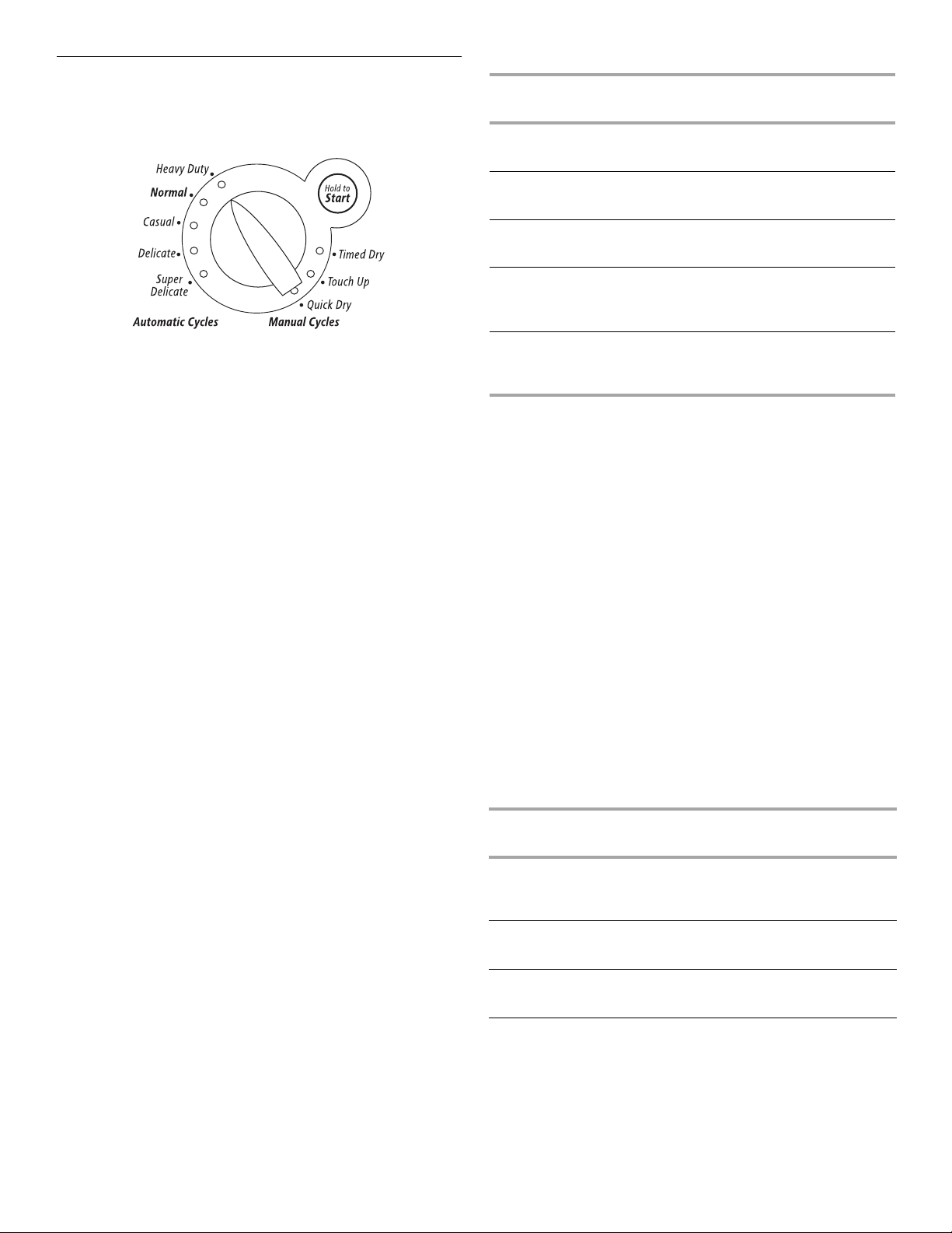
Cycles
Select the drying cycle that matches the type of load you are
drying (see Automatic Preset or Manual Preset Cycle Settings
charts).
Automatic Preset Cycle Settings
Automatic Cycles
Load Type
HEAVY DUTY
Heavyweight, towels
Te mp . T im e *
(Minutes)
High 40
Cycle control knob
Automatic Cycles
Automatic Cycles allow you to match the cycle to the load you
are drying. See the following “Automatic Preset Cycle Settings”
chart. Each cycle dries certain fabrics at the recommended
temperature. A sensor detects the moisture in the load and
automatically adjusts the drying time for optimal drying.
Heavy Duty
Use this cycle to get High heat for heavy fabrics such as cotton
towels or bedspreads.
Normal
Use this cycle to get Medium heat for drying sturdy fabrics such
as work clothes.
Casual
Use this cycle to get Medium heat for drying no-iron fabrics, such
as sport shirts, casual business clothes and permanent press
blends.
Delicate
Use this cycle to get Low heat for drying synthetic fabrics,
washable knit fabrics and no-iron finishes.
Super Delicate
Use this cycle to get Extra Low heat to gently dry items such as
lingerie, exercise wear, or sheer curtains.
NORMAL
Corduroys, work clothes
CASUAL
Permanent press, synthetics
DELICATE
Lingerie, blouses, washable
woolens
SUPER DELICATE
Exercise wear, sheer curtains,
lace
*Estimated Time with Dryness Level (medium) setting.
Medium 34
Medium 36
Low 28
Extra Low 22
Manual Cycles
Use Manual Cycles to select a specific amount of drying time and
a drying temperature. When a Manual Cycle is selected, the
ESTIMATED TIME REMAINING display shows the actual time
remaining in your cycle. You can change the actual time in the
cycle by pressing MORE TIME or LESS TIME.
Timed Dry
Use this cycle to complete drying if items are still damp after an
Automatic Cycle. Timed Dry is also useful for drying heavyweight
and bulky items, such as bedspreads and work clothes.
Touch U p
Use this setting to remove wrinkles from items, such as clothes
packed in a suitcase or items wrinkled from being left in the dryer
too long.
Quick Dry
Use this cycle for drying small loads or loads that need a short
drying time.
Manual Preset Cycle Settings
Manual Cycles
Load Type
Temp. Default Time
(Minutes)
18
TIMED DRY
Heavyweight, bulk,
bedspreads, work clothes
TOUCH UP
Remove wrinkles
QUICK DRY
Small loads
High 40
Medium 20
High 27
Page 19
Additional Features
WRINKLE SHIELD™ Feature
When you are unable to remove a load of clothes from the dryer
as soon as it stops, wrinkles can form. The WRINKLE SHIELD™
feature periodically tumbles, rearranges and fluffs the load to
avoid wrinkles.
■
Press the WRINKLE SHIELD™ feature to get up to
120 minutes of heat-free, periodic tumbling at the end of a
cycle.
■
Stop at any time by pressing the WRINKLE SHIELD™ feature
or opening the dryer door.
■
For the Casual Cycle, the WRINKLE SHIELD™ feature is
preset to “On.” The other Automatic Cycles will retain the
WRINKLE SHIELD™ feature setting. (For example, if you
select the WRINKLE SHIELD™ feature in the Normal cycle,
the WRINKLE SHIELD™ feature will be on the next time you
select the Normal cycle.)
If you do not select the WRINKLE SHIELD™ feature, the
NOTE:
dryer stops after the cool down period.
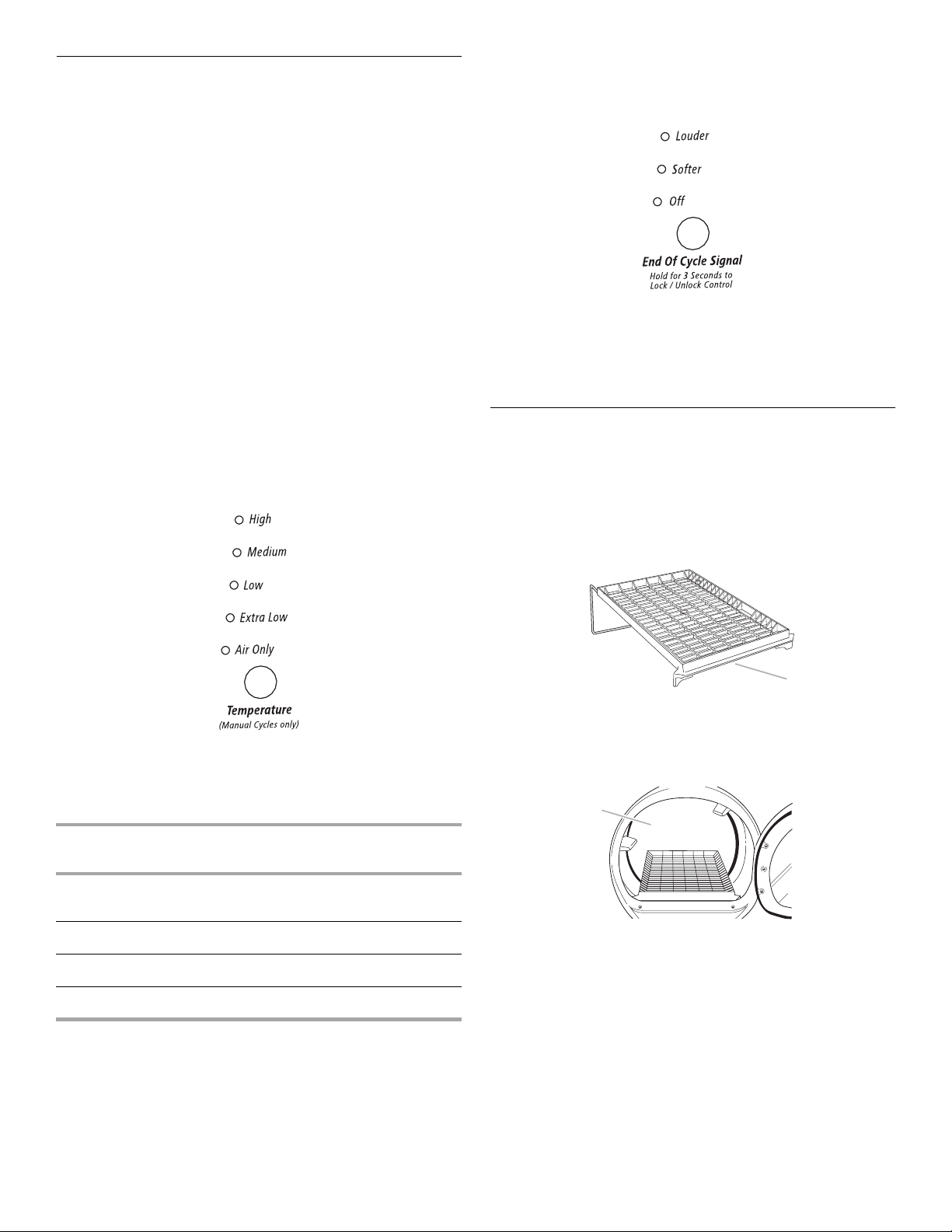
Temperature
Temperature settings are used with the Manual Cycles. Press
TEMPERATURE until the desired temperature setting glows.
Temperature settings cannot be used with the Automatic Cycles.
End of Cycle Signal
The End of Cycle Signal produces an audible sound when the
drying cycle is finished. Promptly removing clothes at the end of
the cycle reduces wrinkling.
Press and release the END OF CYCLE SIGNAL to adjust the
sound level or turn off the signal.
When the WRINKLE SHIELD™ feature is selected and the
NOTE:
End of Cycle Signal is on, an audible sound will emit every
5 minutes until the clothes are removed, or the WRINKLE
SHIELD™ feature is finished.
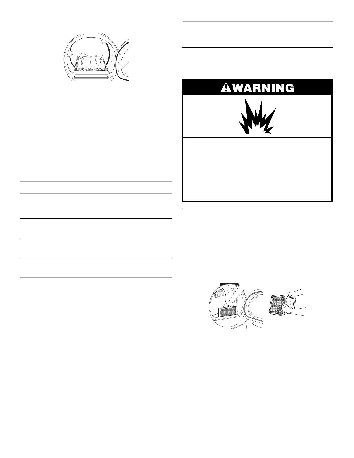
Drying Rack
The drying rack is useful for drying items you would not
necessarily want to tumble dry or that you would normally line dry
(for example, sweaters).
To use the drying rack
Do not remove the lint screen.
Open dryer door.
1.
Air Only
Use the Air Only setting for items that require drying without heat
such as rubber, plastic and heat-sensitive fabrics. This chart
shows examples of items that can be dried using Air Only.
Type of Load Time*
(Minutes)
Foam rubber - pillows, padded bras, stuffed
toys
Plastic - Shower curtains, tablecloths
Rubber-backed rugs
Olefin, polypropylene, sheer nylon
*Reset time to complete drying, if needed.
20 - 30
20 - 30
40 - 50
10 - 20
When using Air Only
■
Check to see that coverings are securely stitched.
■
Shake and fluff pillows by hand periodically during the cycle.
■
Dry item completely. Foam rubber pillows are slow to dry.
Automatic Cycles are not available when using the Air
NOTE:
Only setting.
1
1. Front edge
Place drying rack inside dryer drum, positioning the back wire
2.
on the ledge of the inner dryer back panel. Push down on
front edge of drying rack to secure over the lint screen.
1
1. Dryer back panel
Put the wet items on top of the rack. Leave space between
3.
the items so air can reach all the surfaces.
19
Page 20
NOTE:
4.
5.
6.
7.
NOTE:
automatic cycles with the drying rack.
This chart shows examples of items that can be rack dried and
the suggested cycle, temperature setting and drying time. Actual
drying time will depend on the amount of moisture items hold.
*(Minutes) Reset time to complete drying, if needed.
Do not allow items to hang over the edge of the rack.
Close the door.
Select a timed drying cycle and temperature, or an air cycle
(see following chart). Items containing foam, rubber, or plastic
must be dried on a clothesline or by using the Air Only
temperature setting.
You must select a time by pressing MORE TIME or LESS
TIME. Reset time as needed to complete drying. Refer to the
following table.
Press (and hold) HOLD TO START button (about 1 second).
You must remove rack for normal tumbling. Do not use
Rack Dry Setting Temp. Time*
Wool Sweaters
Block to shape and lay flat on
the rack
Stuffed toys or pillows
Cotton or polyester fiber filled
Stuffed toys or pillows
Foam rubber filled
Sneakers or canvas shoes
Timed
Dry
Timed
Dry
N/A Air Only
N/A Air Only
Low 60
Low 60
90
(no heat)
90
(no heat)
DRYER CARE
Cleaning the Dryer Location
Keep dryer area clear and free from items that would obstruct the
flow of combustion and ventilation air.
Explosion Hazard
Keep flammable materials and vapors, such as
gasoline, away from dryer.
Place dryer at least 18 inches (46 cm) above the
floor for a garage installation.
Failure to do so can result in death, explosion,
or fire.
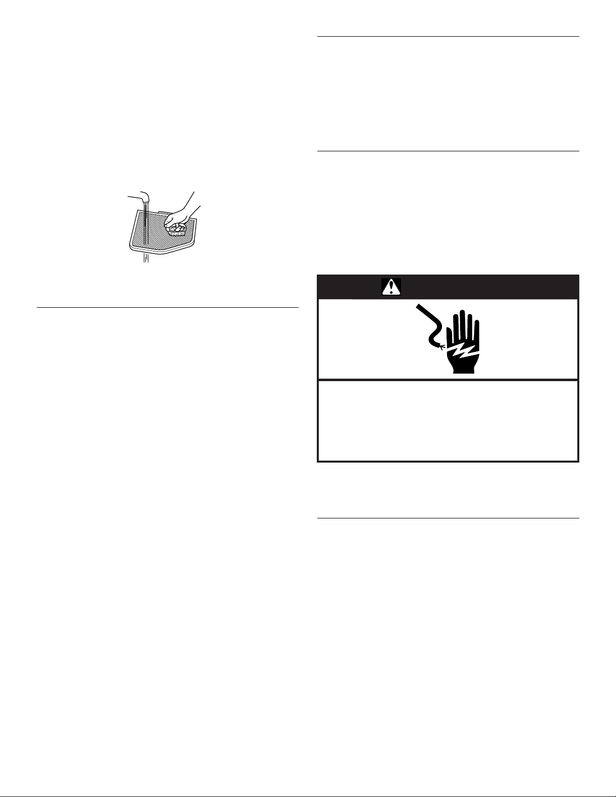
Cleaning the Lint Screen
Every load cleaning
The lint screen is located in the door opening of the dryer. Clean it
before or after each load. A screen blocked by lint can increase
drying time.
To clean
Pull the lint screen straight up. Roll lint off the screen with
1.
your fingers. Do not rinse or wash screen to remove lint. Wet
lint is hard to remove.
20
Push the lint screen firmly back into place.
2.
IMPORTANT:
■
Do not run the dryer with the lint screen loose, damaged,
blocked, or missing. Doing so can cause overheating and
damage to both the dryer and fabrics.
■
Some towels made of synthetic fibers and natural fibers
(polyester and cotton blends) may shed more lint than other
towels, causing your dryer’s lint screen to fill up faster. Be
sure to remove lint from the lint screen before and after drying
new towels.
■
If lint falls off the screen into the dryer during removal, check
the exhaust hood and remove the lint. See “Ve nting
Requirements.”
Page 21
As needed cleaning
Laundry detergent and fabric softener residue can build up on the
lint screen. This buildup can cause longer drying times for your
clothes, or cause the dryer to stop before your load is completely
dry. The screen is probably clogged if lint falls off while the screen
is in the dryer.
Clean the lint screen with a nylon brush every 6 months, or more
frequently, if it becomes clogged due to a residue buildup.
To wash
Roll lint off the screen with your fingers.
1.
Wet both sides of lint screen with hot water.
2.
Wet a nylon brush with hot water and liquid detergent. Scrub
3.
lint screen with the brush to remove residue buildup.
Rinse screen with hot water.
4.
Thoroughly dry lint screen with a clean towel. Replace screen
5.
in dryer.
Cleaning the Dryer Interior
Removing Accumulated Lint
From Inside the Dryer Cabinet
Lint should be removed every 2 years or more often, depending
on dryer usage. Cleaning should be done by a qualified person.
From the Exhaust Vent
Lint should be removed every 2 years, or more often, depending
on dryer usage.
Vacation and Moving Care
Vacation care
Operate your dryer only when you are at home. If you will be on
vacation or not using your dryer for an extended period of time,
you should:
Unplug dryer or disconnect power.
1.
Wash lint screen.
2.
Moving care
WARNING
To clean dryer drum
Make a paste with powdered laundry detergent and very
1.
warm water.
Apply paste to a soft cloth.
2.
OR
Apply a liquid, nonflammable household cleaner to the
stained area and rub with a soft cloth until all excess dye and
stains are removed.
Wipe drum thoroughly with a damp cloth.
3.
Tumble a load of clean cloths or towels to dry drum.
4.
NOTE:
blue jeans or brightly colored cotton items, may discolor the
dryer interior. These stains are not harmful to your dryer and will
not stain future loads of clothes. Dry unstable dye items inside
out to prevent dye transfer.
Garments which contain unstable dyes, such as denim
Electrical Shock Hazard
Disconnect power before servicing.
Replace all parts and panels before operating.
Failure to do so can result in death or
electrical shock.
Unplug dryer or disconnect power. Disconnect wiring if dryer
1.
is direct wired.
Make sure leveling legs are secure in dryer base.
2.
Use masking tape to secure dryer door.
3.
Changing the Drum Light
The dryer light automatically turns on inside the dryer drum when
you open the door.
To change the drum light
Unplug dryer or disconnect power.
1.
Open the dryer door. Locate the light bulb cover on the back
2.
wall of the dryer. Remove the screw located in the lower right
corner of the cover. Remove the cover.
Turn bulb counterclockwise. Replace the bulb with a 10-watt
3.
appliance bulb only. Replace the cover and secure with the
screw.
Plug in dryer or reconnect power.
4.
21
Page 22
TROUBLESHOOTING
First try the solutions suggested here and possibly avoid
the cost of a service call...
Dryer displaying code message
■
“PF” (power failure), check the following:
Was the drying cycle interrupted by a power failure?
Press (and hold) HOLD TO START button to restart the dryer.
■
“E” Variable (E1, E2, E3) service codes:
Call for service.
Clothes are not drying satisfactorily
■
Check the following:
Is the lint screen clogged with lint?
Is the exhaust vent or outside exhaust hood clogged with lint,
restricting air movement? Run the dryer for 5-10 minutes.
Hold your hand under the outside exhaust hood to check air
movement. If you do not feel air movement, clean exhaust
system of lint or replace exhaust vent with heavy metal or
flexible metal vent. See “Installation Instructions.”
Is the exhaust vent crushed or kinked? Replace with a heavy
metal or flexible metal vent. See “Installation Instructions.”
Has a fuse blown, or has a circuit breaker tripped? Electric
dryers use 2 household fuses or breakers. The drum may be
turning, but you may not have heat.
Has an air cycle been selected? Select the right cycle for the
types of garments being dried. See “Cycles.”
Is the automatic cycle ending early? The load may not be
contacting the electronic sensor strips. Level the dryer.
Are fabric softener sheets blocking the grille? Use only one
fabric softener sheet and only use it once.
■
Is the dryer located in a room with temperature below
45ºF (7ºC)?
Proper operation of dryer cycles requires temperatures above
45ºF (7ºC).
■
Was a cold rinse water used? Was the load very wet?
Expect longer drying times with items rinsed in cold water
and with items that hold moisture (cottons).
■
Is the load too large and heavy to dry quickly?
Separate the load to tumble freely.
Dryer will not run
■
Check the following:
Is the power cord plugged in?
Has a fuse blown, or has a circuit breaker tripped?
Was a regular fuse used? Use a time-delay fuse.
Is the dryer door firmly closed? If not, the time display will
blink.
Was HOLD TO START firmly pressed and held for at least
1 second?
Is a cycle selected?
Unusual sounds
■
Has the dryer had a period of non-use?
If the dryer hasn’t been used for a while, there may be a
thumping sound during the first few minutes of operation.
Lint on load
■
Is the lint screen clogged?
Clean lint screen. Check for air movement.
■
Is load properly sorted?
Sort lint givers (towels, chenille) from lint takers (corduroy,
synthetics). Also sort by color.
■
Is the load too big or too heavy?
Dry smaller loads so lint can be carried to the lint screen.
■
Was the load overdried?
Use correct dryer settings for load type. See “Cycles.”
Overdrying can cause lint-attracting static electricity.
■
Was paper or tissue left in pockets?
■
Is pilling being mistaken for lint?
Pilling (surface fuzz) is caused by normal wear and
laundering.
Stains on load or color change
■
Was dryer fabric softener properly used?
Add dryer fabric softener sheets at the beginning of the cycle
when the load is cold. Do not add fabric softener sheets to a
warm load.
■
Were items soiled when placed in the dryer?
Items should be clean before being dried.
■
Were items properly sorted?
Sort light colors from dark colors. Sort colorfast items from
noncolorfast items.
22
Page 23

Items shrinking
■
Was the dryer overloaded?
Dry smaller loads that can tumble freely.
■
Did the load overdry?
Check the manufacturer’s care label. Match dryer setting to
load type. See “Cycles.”
Loads are wrinkled
ASSISTANCE OR SERVICE
Before calling for assistance or service, please check
“Troubleshooting.” It may save you the cost of a service call. If
you still need help, follow the instructions below.
When calling, please know the purchase date and the complete
model and serial number of your appliance. This information will
help us to better respond to your request.
■
Was load removed from dryer at the end of the cycle?
■
Was dryer overloaded?
Dry smaller loads that can tumble freely.
■
Did load overdry?
Check the manufacturer’s care label. Match dryer setting to
load type. See “Cycles.”
Odors
■
Have you recently been painting, staining or varnishing in
the area where your dryer is located?
If so, ventilate the area. When the odors or fumes are gone
from the area, rewash and dry the clothing.
■
Is the dryer being used for the first time?
The new electric heating element may have an odor. The odor
will be gone after the first cycle.
Garment damage
■
Check the following:
Were zippers, snaps, and hooks left open?
Were strings and sashes tied to prevent tangling?
Were care label instructions followed?
Were items damaged before drying?
If you need replacement parts
If you need to order replacement parts, we recommend that you
use only FSP
and work right because they are made with the same precision
used to build every new WHIRLPOOL
replacement parts in your area, call our Customer Interaction
Center telephone number or your nearest designated service
center.
®
factory specified parts. These parts will fit right
®
appliance. To locate FSP
®
For assistance and service
Call the Whirlpool Customer Interaction Center toll free:
1-800-253-1301.
Our consultants provide assistance with:
■
Features and specifications on our full line of appliances
■
Installation information
■
Use and maintenance procedures
■
Accessory and repair parts sales
■
Specialized customer assistance (Spanish speaking, hearing
impaired, limited vision, etc.)
■
Referrals to local dealers, repair parts distributors, and
service companies
Whirlpool designated service technicians are trained to fulfill the
product warranty and provide after-warranty service, anywhere in
the United States.
To locate the Whirlpool designated service company in your area,
you can also look in your telephone directory Yellow Pages.
For further assistance
If you need further assistance, you can write to Whirlpool
Corporation with any questions or concerns at:
Whirlpool Corporation
Customer Interaction Center
553 Benson Road
Benton Harbor, MI 49022-2692
Please include a daytime phone number in your correspondence.
Accessories U.S.A.
To order accessories, call the Whirlpool Customer Interaction
Center toll free at
1-800-442-9991
Or visit our website at
www.whirlpool.com
and follow the menu prompts.
.
23
Page 24
WHIRLPOOL® DRYER WARRANTY
ONE YEAR FULL WARRANTY
For one year from the date of purchase, when this dryer is operated and maintained according to instructions attached to or furnished
with the product, Whirlpool Corporation will pay for FSP
workmanship. Service must be provided by a Whirlpool designated service company.
SECOND YEAR LIMITED WARRANTY ON ELECTRONIC CONTROL BOARDS
In the second year from the date of purchase, when this dryer is operated and maintained according to instructions attached to or
furnished with the product, Whirlpool Corporation will pay for FSP
defective in materials or workmanship.
SECOND THROUGH FIFTH YEAR LIMITED WARRANTY ON PORCELAIN TOP
In the second through fifth years from the date of purchase, when this dryer is operated and maintained according to instructions
attached to or furnished with the product, Whirlpool Corporation will pay for FSP replacement parts to replace the porcelain top should
it chip or rust due to defective materials or workmanship.
Whirlpool Corporation will not pay for:
Service calls to correct the installation of your dryer, including venting. Heavy 4 in. (10.2 cm) metal exhaust vent must be used. Refer
1.
to the venting section of this manual and your Installation Instructions.
Service calls to instruct you how to use your dryer, to replace house fuses or correct house wiring or reset circuit breakers, or to
2.
replace owner accessible light bulbs.
Repairs when your dryer is used in other than normal, single-family household use.
3.
Damage resulting from accident, alteration, misuse, abuse, fire, floods, acts of God, improper installation (including, but not limited
4.
to, venting with plastic or flexible foil), installation not in accordance with local electrical and plumbing codes, or use of products not
approved by Whirlpool Corporation.
Replacement parts or repair labor costs for units operated outside the United States.
5.
Pickup and delivery. This product is designed to be repaired in the home.
6.
Repairs to parts or systems resulting from unauthorized modifications made to the appliance.
7.
Any labor costs incurred during the Limited Warranty periods.
8.
®
replacement parts and repair labor costs to correct defects in materials or
®
replacement parts to replace the electronic control boards if
WHIRLPOOL CORPORATION SHALL NOT BE LIABLE FOR INCIDENTAL OR CONSEQUENTIAL DAMAGES.
Some states do not allow the exclusion or limitation of incidental or consequential damages, so this exclusion or limitation may not
apply to you. This warranty gives you specific legal rights and you may also have other rights which vary from state to state.
Outside the 50 United States, this warranty does not apply. Contact your authorized Whirlpool dealer to determine if another
warranty applies.
If you need service, first see “Troubleshooting.” Additional help can be found by checking “Assistance or Service,” or by calling our
Customer Interaction Center at
1-800-253-1301
Center, 553 Benson Road, Benton Harbor, MI 49022-2692.
Keep this book and your sales slip together for future
reference. You must provide proof of purchase or installation
date for in-warranty service.
Write down the following information about your dryer to better
help you obtain assistance or service if you ever need it. You will
need to know your complete model number and serial number.
You can find this information on the model and serial number
label, located at the top inside dryer door well.
, from anywhere in the U.S.A. or write: Whirlpool Corporation, Customer Interaction
7/03
Dealer name____________________________________________________
Address ________________________________________________________
Phone number __________________________________________________
Model number __________________________________________________
Serial number __________________________________________________
Purchase date __________________________________________________
8533582
© 2003 Whirlpool Corporation.
All rights reserved. ® Registered Trademark/TM Trademark of Whirlpool, U.S.A.
Printed in U.S.A.
12/03
 Loading...