

Page 1
MICROWAVE HOOD COMBINATION
INSTALLATION INSTRUCTIONS
This product is suitable for use above electric or gas cooking products up to 36" (91.4 cm) wide.
These installation instructions cover different models. The appearance of your particular model may differ slightly from the
illustration in these installation instructions.
NOTES:
■ Proper installation is the responsibility of the installer.
■ Product failure due to improper installation is not covered under the warranty.
Table of Contents
MICROWAVE HOOD COMBINATION SAFETY .............................. 1
INSTALLATION REQUIREMENTS ...................................................2
Tools and Parts...............................................................................2
Location Requirements................................................................... 2
Product Dimensions .......................................................................3
Electrical Requirements.................................................................. 3
INSTALLATION INSTRUCTIONS .....................................................4
Remove Mounting Plate .................................................................4
Rotate Blower Motor....................................................................... 4
Locate Wall Stud(s)......................................................................... 6
Mark Rear Wall................................................................................ 7
Drill Holes in Rear Wall.................................................................... 7
Attach Mounting Plate to Wall ........................................................8
Prepare Upper Cabinet................................................................... 8
Install Damper Assembly ................................................................9
Install the Microwave Oven ............................................................ 9
Complete Installation ....................................................................10
VENTING DESIGN SPECIFICATIONS............................................11
ASSISTANCE ................................................................................... 12
Replacement Parts .......................................................................12
Accessories...................................................................................12
MICROWAVE HOOD COMBINATION SAFETY
Your safety and the safety of others are very important.
We have provided many important safety messages in this manual and on your appliance. Always read and obey all safety
messages.
This is the safety alert symbol.
This symbol alerts you to potential hazards that can kill or hurt you and others.
All safety messages will follow the safety alert symbol and either the word “DANGER” or “WARNING.”
These words mean:
You can be killed or seriously injured if you don't immediately
DANGER
WARNING
All safety messages will tell you what the potential hazard is, tell you how to reduce the chance of injury, and tell you what can
happen if the instructions are not followed.
IMPORTANT: Read Installation Instructions thoroughly before beginning installation. Save Installation Instructions for local house
inspector’s use.
follow instructions.
can be killed or seriously injured if you don't
You
instructions.
follow
8206327
Page 2
INSTALLATION REQUIREMENTS
Tools and Parts
Tools Needed
Gather the required tools and parts before starting installation.
Read and follow the instructions provided with any tools
listed here.
■ Measuring tape
■ Pencil
■ Masking tape or thumbtacks
■ Scissors
■ No. 2 Phillips screwdriver
■ No. 3 Phillips screwdriver for
1/4-20 x 3" round-head bolts
■ Electric drill
■ 3/16" (5 mm), 3/8" (10 mm)
drill bits
■ 3/4" (19 mm) hole saw
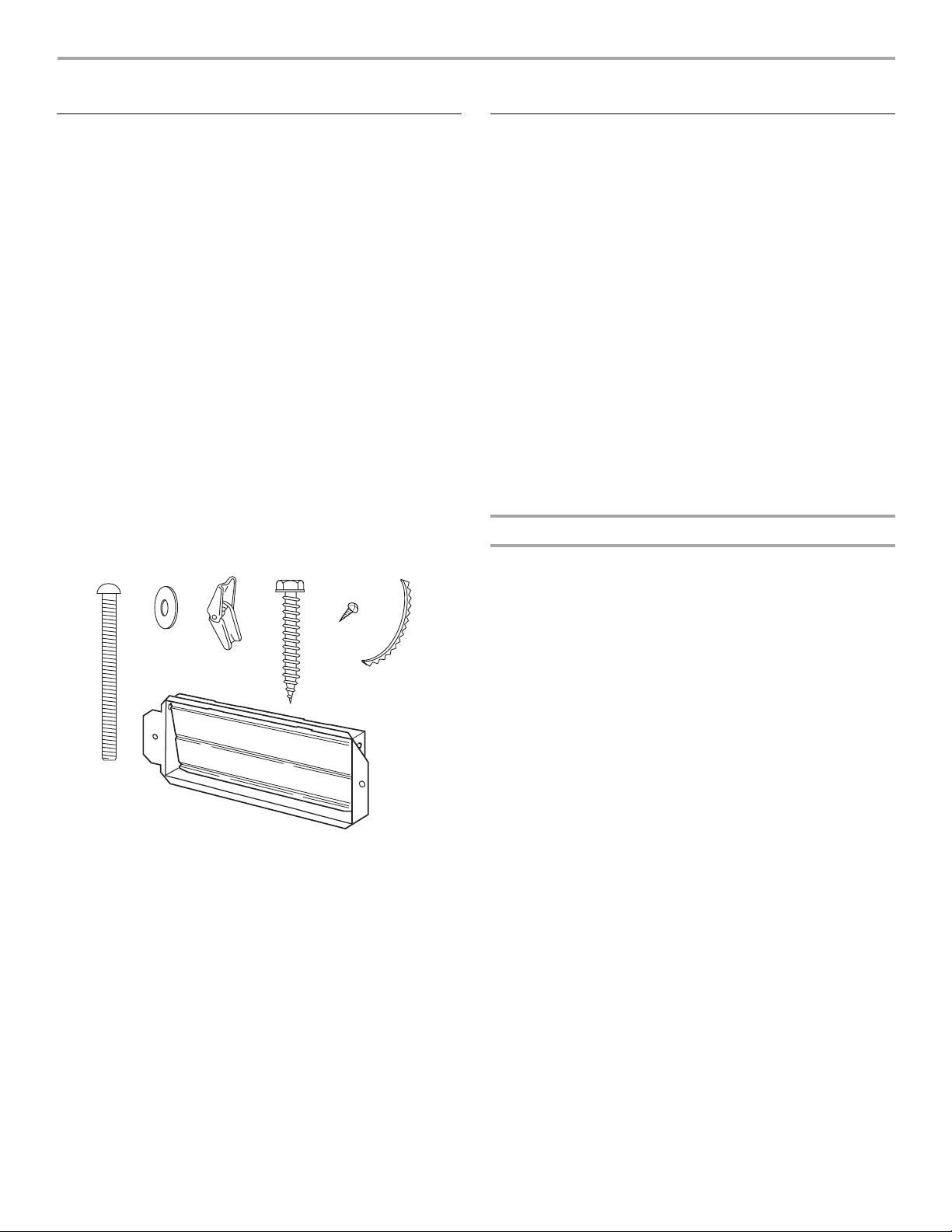
Parts Supplied
For reorder information, see “Replacement Parts” section.
NOTE: The hardware items listed here are for wood studs. For
other types of wall structures, be sure to use appropriate
fasteners.
A
B
G
C
■ Stud finder
■ 7/16" socket wrench
(or box wrench) for 1/4" x 2"
lag screws
■ 1½" (3.8 cm) diam. hole drill
bit for wood or metal
cabinet
■ Keyhole saw
■ Caulking gun and
weatherproof caulking
compound
■ Duct tape
DEF
Location Requirements
Check the opening where the microwave oven will be installed.
The location must provide:
■ Minimum installation dimensions. See “Installation
Dimensions” illustration.
■ Minimum one 2" x 4" (50.8 x 101.6 mm) wood wall stud and
minimum 3/8" (9.5 mm) thickness drywall or plaster/lath within
cabinet opening.
■ Support for weight of 150 lbs (68 kg), which includes
microwave oven and items placed inside the microwave oven
and upper cabinet.
■ Grounded electrical outlet inside upper cabinet. See
“Electrical Requirements” section.
NOTES:
■ If installing the microwave oven near a left sidewall, make sure
there is at least 6" (15.2 cm) of clearance between the wall and
the microwave oven, so that the door can open fully.
■ Some cabinet and building materials are not designed to
withstand the heat produced by the microwave oven for
cooking. Check with your builder or cabinet supplier to make
sure that the materials used will not discolor, delaminate or
sustain other damages.
Special Requirements
For Wall Venting Installation Only:
■ Cutout must be free of any obstructions so that the vent tube
fits properly, and the damper blade opens freely and fully.
For Roof Venting Installation Only:
■ If you are using rectangular to round transition piece, the 3"
(7.6 cm) clearance needs to exist above the microwave oven
so that the damper blade can open freely and fully. See
“Rectangular to Round Transition” illustration in “Venting
Design Specifications” section.
A. 1/4-20 x 3" bolts (6)
B. Washers (2)
C. Toggle nuts (4)
D. 1/4" x 2" lag screws (4)
E. Sheet metal screws (2)
F. Power supply cord bushing (1)
G. Damper assembly (for wall or roof
venting)
Not Shown:
Upper cabinet template
Mounting plate (attached to
back of microwave oven)
Aluminum grease filters
Charcoal filters (Depending
on model, charcoal filters
may not be included. See
Use and Care Guide.)
NOTE: Depending on model, aluminum grease filter and charcoal
filter may be combined.
Materials needed
■ Standard fittings for wall or roof venting. See “Venting Design
Specifications” section.
2
Page 3
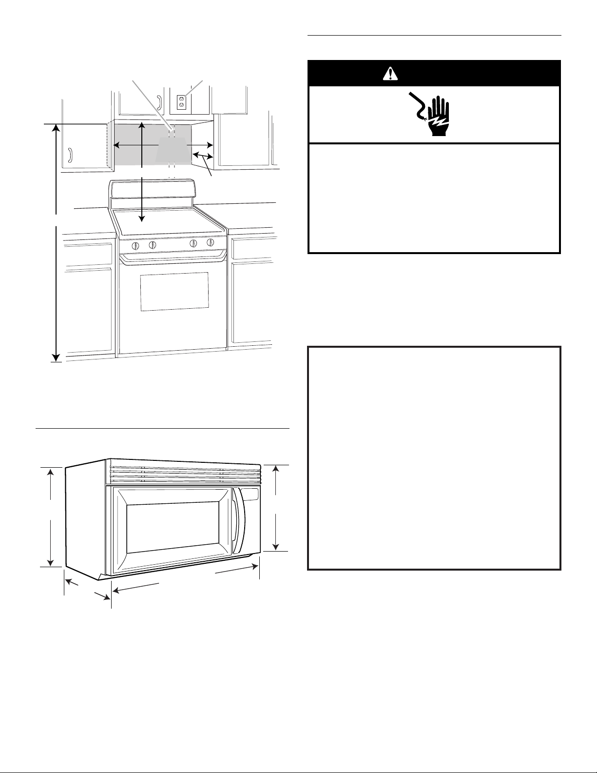
Installation Dimensions
(
NOTE: The grounded 3 prong outlet must be inside the upper
cabinet. See “Electrical Requirements” section.
Electrical Requirements
66" (167.6 cm) min.
A B
30"
(76.2 cm)
min.
30" (76.2 cm) typical*
12" (30.5 cm) min.
14" (35.6 cm) max.
WARNING
Electrical Shock Hazard
Plug into a grounded 3 prong outlet.
Do not remove ground prong.
Do not use an adapter.
Do not use an extension cord.
Failure to follow these instructions can result in death,
fire, or electrical shock.
Observe all governing codes and ordinances.
Required:
■ A 120 Volt, 60 Hz, AC only, 15- or 20-amp electrical supply
with a fuse or circuit breaker.
Recommended:
■ A time-delay fuse or time-delay circuit breaker.
■ A separate circuit serving only this microwave oven.
A. 2" x 4" wall stud
B. Grounded 3 prong outlet
*30" (76.2 cm) is typical for 66" (167.6 cm) installation height.
Exact dimensions may vary depending on type of range/cooktop
below.
Product Dimensions
"
¹⁄₈
17
43.5 cm)
15
³⁄₈
(39.1 cm)
" (75.9 cm
⁷⁄₈
"
29
)
15
(40.3 cm)
GROUNDING INSTRUCTIONS
■
For all cord connected appliances:
The microwave oven must be grounded. In the event of
an electrical short circuit, grounding reduces the risk of
electric shock by providing an escape wire for the electric
current. The microwave oven is equipped with a cord
having a grounding wire with a grounding plug. The plug
must be plugged into an outlet that is properly installed
and grounded.
WARNING: Improper use of the grounding plug can
result in a risk of electric shock. Consult a qualified
electrician or serviceman if the grounding instructions are
"
⁷⁄₈
not completely understood, or if doubt exists as to whether
the microwave oven is properly grounded.
Do not use an extension cord. If the power supply cord is
too short, have a qualified electrician or serviceman install
an outlet near the microwave oven.
SAVE THESE INSTRUCTIONS
3
Page 4
INSTALLATION INSTRUCTIONS
A
B
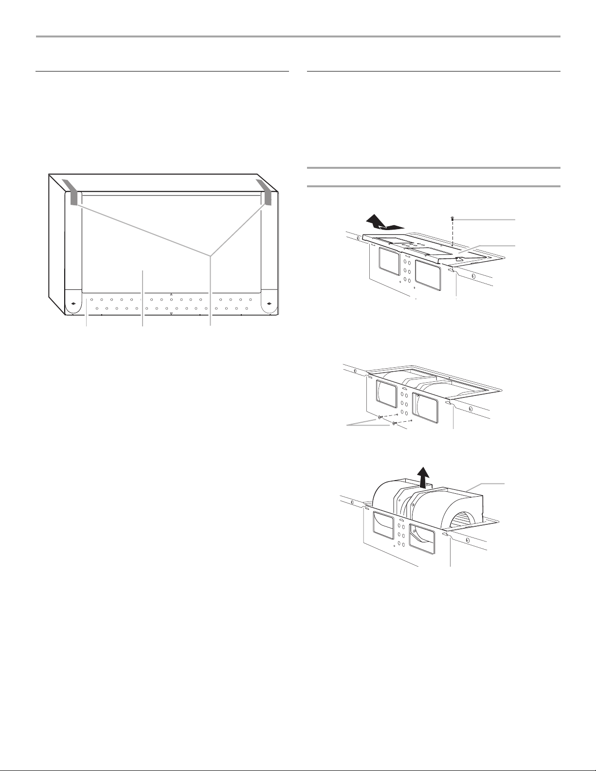
Remove Mounting Plate
NOTE: To avoid possible damage to the work surface, place a
protective cover on the work surface.
1. Remove any remaining contents from the microwave oven
cavity.
2. Remove the mounting plate by peeling off the strips of tape
that attach it to the back of the microwave oven, and set the
mounting plate aside.
A B C
A. Mounting plate
B. Back of microwave oven
C. Tape (multiple locations)
Rotate Blower Motor
The microwave oven is set for ventless (recirculating) installation.
For wall or roof venting, changes must be made to the venting
system.
NOTE: Skip this section if you are using ventless (recirculating)
installation. Keep the damper assembly in case the venting
method is changed, or the microwave oven is reinstalled in
another location where wall or roof venting may be used.
Wall Venting Installation Only
1. Remove screw attaching damper plate to top of microwave
oven exterior. Slide damper plate back and lift up.
AScrew
B. Damper plate
2. Keep damper plate and screw together and set aside.
3. Remove two screws attaching blower motor to back of
microwave oven.
3. Tape the microwave oven door closed so that door does not
swing open while the microwave oven is being handled.
NOTE: Do not grip or use the door or door handle while the
microwave oven is being handled.
A
A. Screws
4. Lift blower motor out of microwave oven.
A
A. Blower motor
4
Page 5
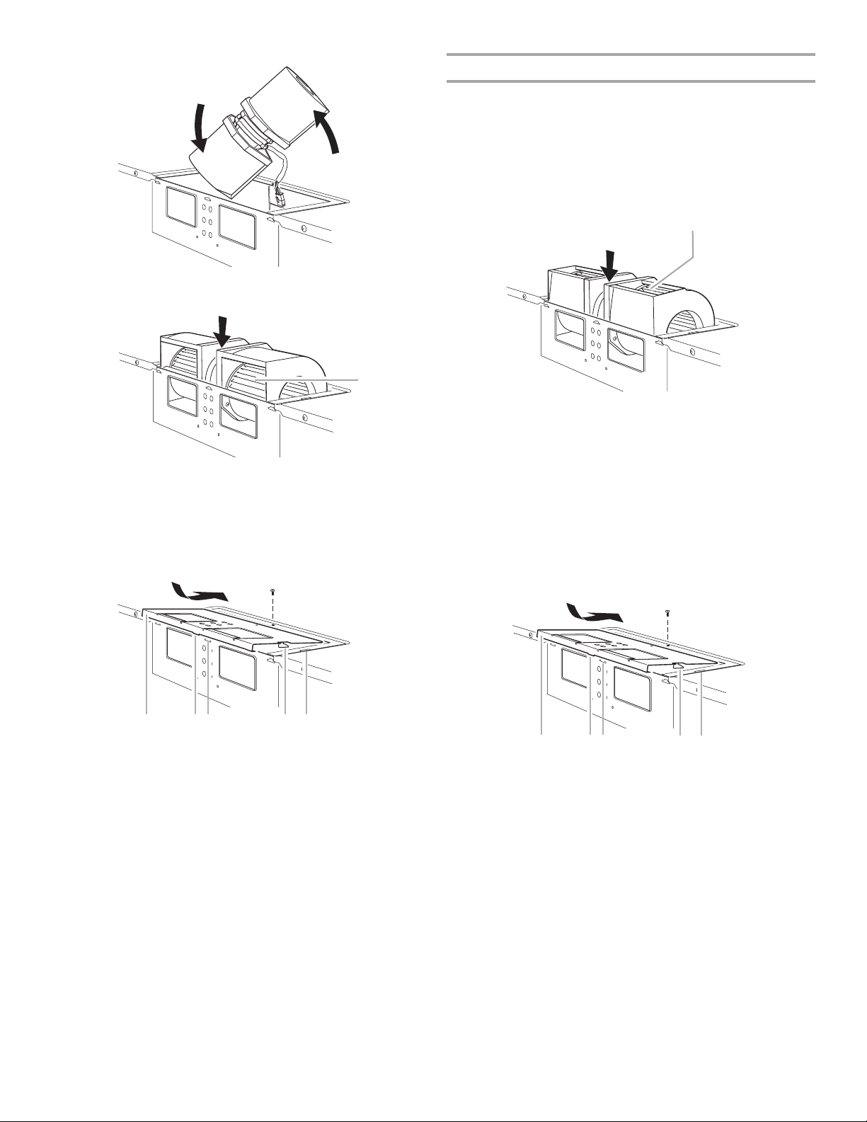
5. Rotate blower motor end over end.
A
6. Rotate blower motor so that exhaust ports face the back of
microwave oven, and lower it back into the microwave oven.
A. Exhaust port
7. Reattach blower motor to back of microwave oven with
2 screws removed in Step 3.
8. Reattach damper plate. Make sure tabs at top and back of
damper plate are inserted fully into their respective slots in the
microwave oven
.
Roof Venting Installation Only
1. Repeat Step 1 from “Wall Venting Installation Only.”
2. Repeat Step 2 from “Wall Venting Installation Only.”
3. Repeat Step 3 from “Wall Venting Installation Only.”
4. Repeat Step 4 from “Wall Venting Installation Only.”
5. Rotate blower motor so that exhaust ports face the top of
microwave oven, and flat sides of blower motor face back of
microwave oven. Lower blower motor back into microwave
oven.
A
A. Exhaust port
IMPORTANT: If blower motor is not positioned with flat sides
facing the back of the microwave oven (as shown), performance
will be poor.
6. Reattach blower motor to back of microwave oven with
2 screws removed in Step 3 of “Wall Venting Installation Only.”
Securely tighten screws.
NOTE: If blower motor is not correctly oriented, the 2 screws
removed in Step 3 cannot be reattached to the microwave oven.
7. Reattach damper plate. Make sure tabs at top and back of
damper plate are inserted fully into their respective slots in the
microwave oven.
A B C D E
A. Damper plate
B. Tabs at back of damper plate
C. Slots in back of microwave oven exterior
D. Damper plate tabs
E. Slots in top of microwave oven exterior
9. Secure damper plate with screw.
A B C D E
A. Damper plate
B. Tabs at back of damper plate
C. Slots in back of microwave oven exterior
D. Damper plate tabs
E. Slots in top of microwave oven exterior
8. Secure damper plate with screw.
5
Page 6
Locate Wall Stud(s)
A
A
D
MOUNTING PLATE
MOUNTING PLATE
A
A
C
D
MOUNTING PLATE
MOUNTING PLATE
D
D
MOUNTING PLATE
MOUNTING PLATE
MOUNTING PLATE
MOUNTING PLATE
D
D
NOTE: If no wall studs exist within the cabinet opening, do not
install the oven.
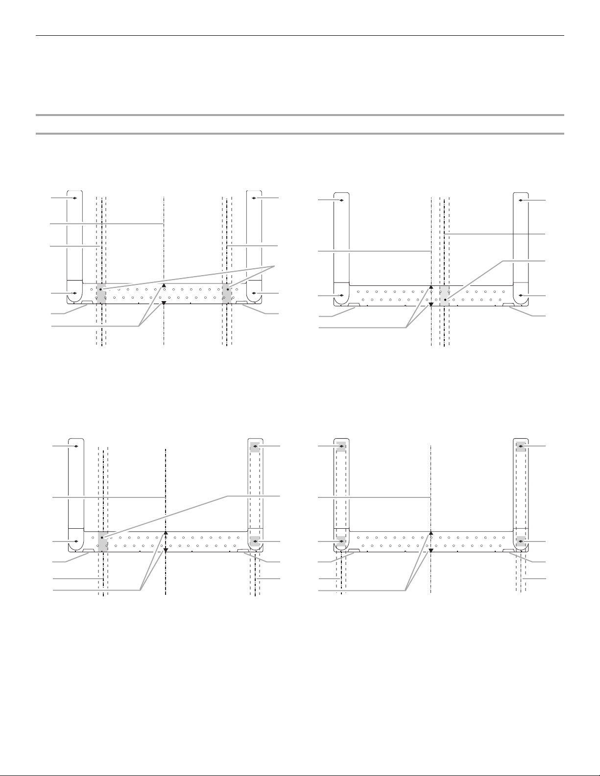
See illustrations in “Possible Wall Stud Configurations.”
Possible Wall Stud Configurations
These depictions show examples of preferred installation configurations with the mounting plate.
1. Using a stud finder, locate the edges of the wall stud(s) within
the opening.
2. Mark the center of each stud, and draw a plumb line down
each stud center. See illustrations in “Possible Wall Stud
Configurations.”
No Wall Studs at Corner Holes
Figure 1
A
A
No Wall Studs at Corner Holes
Figure 2
B
C
A
E
F
C
B
A
E
E
E
F
NOTE: If wall stud is within 6" (15.2 cm) of the vertical
centerline (see “Mark Rear Wall” section), only recirculation or
roof venting installation can be done.
One Wall Stud at Two Corner Holes
Figure 3
A
A,
,D
Wall Studs at All Four Corner Holes
Figure 4
A,
6
B
A
E
C
D
A,
E
C
F
A. Corner holes (on mounting plate)
B. Cabinet opening vertical centerline
C. Wall stud centerlines
D. Holes for lag screws
E. Support tabs
F. Mounting plate center markers
,D
B
A,
E
C
E
C
F
Page 7
Mark Rear Wall
D
The microwave oven must be installed on a minimum of 1 wall
stud, preferably 2, using a minimum of 1 lag screw, preferably 2 or
more.
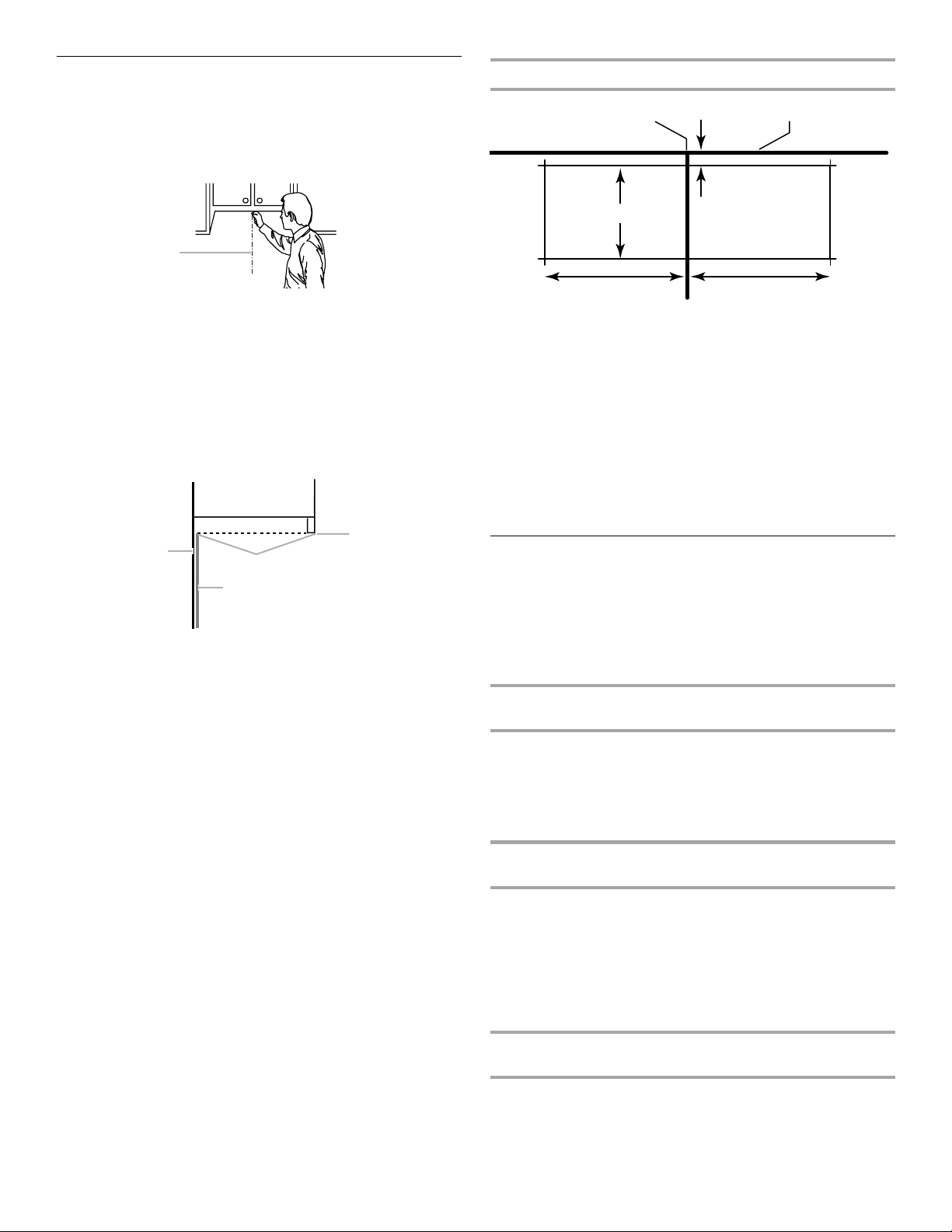
1. Using measuring tape, find and clearly mark the vertical
centerline of the opening.
A
A. Centerline
2. With the support tabs facing forward (see illustrations in
“Possible Wall Stud Configurations” in “Locate Wall Stud(s)”
section), align the mounting plate center markers to the
centerline on the wall, making sure it is level, and that the top
of the mounting plate is butted up against the bottom edge of
the upper cabinet.
NOTE: If the front edge of the upper cabinet is lower than the
back edge, lower the mounting plate so that its top is level with
the front edge of the cabinet.
Wall Venting Installation Only
Centerline
4" (10.2 cm)
6" (15.2 cm) 6" (15.2 cm)
6. Mark the centerline 3/8" (1 cm) down from the bottom edge of
the upper cabinet.
7. Using measuring tape, measure out 6" (15.2 cm) on both sides
of the centerline, and mark.
8. Measure down 4" (10.2 cm) from the mark made in Step 6,
and mark.
9. Using a straightedge, draw the 2 horizontal, level lines through
the marks made in steps 6 and 8.
10. Draw the 2 vertical, plumb lines down from the marks made in
Step 7 to complete the 12" x 4" (30.5 x 10.2 cm) rectangle.
This is the venting cutout area.
11. Cut a 3/4" (19 mm) hole in one corner of the cutout area.
12. Using a keyhole saw, cut out the venting cutout area.
Upper cabinet bottom
³⁄₈" (1 cm)
A
C
B
A. Rear wall
B. Mounting plate
C. Top of mounting plate must align
with front edge of cabinet.
D. Front edge of upper cabinet
3. Holding the mounting plate in place, mark the 4 corner holes.
4. Find the wall stud centerline(s) marked in Step 2 of “Locate
Wall Stud(s),” and mark at least 1, preferably 2 or more, hole(s)
through the mounting plate, closest to the centerline(s). See
figures 1, 2 and/or 3 in “Possible Wall Stud Configurations” in
“Locate Wall Stud(s)” section. The blackened holes in the
shaded areas are ideal hole locations.
5. Set mounting plate aside.
Drill Holes in Rear Wall
In addition to being installed on at least 1 wall stud, the mounting
plate must attach to the wall at all 4 corner holes. If the holes are
not over wall studs, use four 1/4-20 x 3" round-head bolts with
toggle nuts; if 2 holes are over wall studs, use 2 each of lag
screws and 1/4-20 x 3" round-head bolts with toggle nuts; or if all
4 holes are over wall studs, use 4 lag screws. Following are 3
installation configurations.
Installation for No Wall Studs at Corner Holes
(Figures 1 & 2)
1. Drill 3/4" (19 mm) holes through the wall at all 4 corner holes
marked in Step 3 of “Mark Rear Wall.”
2. Drill 3/16" (5 mm) hole(s) into the wall stud(s) at the hole(s)
marked in Step 4 of “Mark Rear Wall.” Refer to figures 1 and 2
in “Possible Wall Stud Configurations” in “Locate Wall Stud(s)”
section.
Installation for One Wall Stud at Two Corner Holes
(Figure 3)
1. Drill 3/16" (5 mm) holes into the wall stud at the 2 corner holes
marked in Step 3 of “Mark Rear Wall.”
2. If installing on a second wall stud, drill 3/16" (5 mm) hole(s)
into the wall stud at the holes marked in Step 4 of “Mark Rear
Wall.” Refer to Figure 3 in “Possible Wall Stud Configurations.”
in “Locate Wall Stud(s)” section.
3. Drill 3/4" (19 mm) holes through the wall at the other 2 corner
holes.
Installation for Wall Studs at All Four Corner Holes
(Figure 4)
1. Drill 3/16" (5 mm) holes into the studs at the 4 corner holes
marked in Step 3 of “Mark Rear Wall.”
7
Page 8
Attach Mounting Plate to Wall
C
C
D
NOTE: Secure the mounting plate to the wall at all 4 corner holes
drilled into the wall studs and/or drywall using either 1/4-20 x 3"
round-head bolts and toggle nuts or 1/4 x 2" lag screws.
Refer to illustrations in “Possible Wall Stud Configurations” in
“Locate Wall Stud(s)” section.
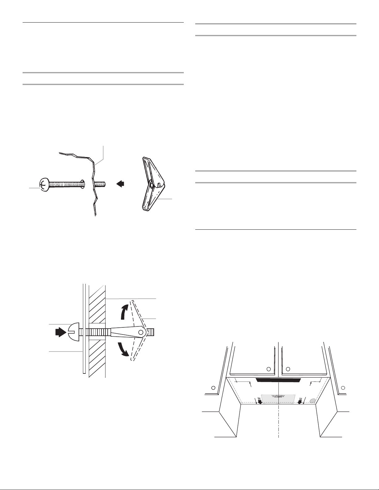
No Wall Studs at Corner Holes (Figures 1 & 2)
NOTE: The mounting plate must also be secured to the wall on at
least 1 wall stud as well as at all 4 corners.
1. With the support tabs of the mounting plate facing forward,
insert 1/4-20 x 3" round-head bolts through all 4 corner holes
of mounting plate.
2. Start toggle nuts on bolts from the back of the mounting plate.
Leave enough space for the toggle nuts to go through the wall
and open.
B
One Wall Stud at Two Corner Holes (Figure 3)
1. With the support tabs of the mounting plate facing forward,
insert 1/4-20 x 3" round-head bolts through the 2 corner holes
that fit over the two 3/4" (19 mm) holes drilled in Step 2 of
“Installation for One Wall Stud at Two Corner Holes” in the
“Drill Holes in Rear Wall” section.
2. Start toggle nuts on the bolts from the back of the mounting
plate. Leave enough space for the toggle nut to go through
the wall and to open.
3. Position mounting plate on the wall, making sure that the top
of the mounting plate is aligned with the front edge of the
upper cabinet.
4. Push the 2 bolts with toggle nuts through the drywall, and
finger tighten the bolts to make sure toggle nuts have opened
against drywall.
5. Insert 2 lag screws into the remaining 2 corner holes.
6. If installing on a second wall stud, insert lag screw(s) into the
other hole(s) drilled in Step 2 of “Installation for One Wall Stud
at Two Corner Holes” in the “Drill Holes in Rear Wall” section.
7. Check alignment of mounting plate, making sure it is level.
8. Securely tighten all lag screws and bolts.
Wall Studs at All Four Corner Holes (Figure 4)
A
A. 1/4-20 x 3" round-head bolt
B. Mounting plate
C. Spring toggle nut
3. Position mounting plate on the wall, making sure that the top
of the mounting plate is aligned with the front edge of the
upper cabinet.
4. Push the 4 bolts with toggle nuts through the drywall, and
finger tighten the bolts to make sure toggle nuts have opened
against drywall.
A
B
1. Position mounting plate on the wall, making sure that the top
of the mounting plate is aligned with the front edge of the
upper cabinet.
2. Insert lag screws into the 4 corner holes.
3. Check alignment of mounting plate, making sure it is level.
4. Securely tighten all lag screws.
Prepare Upper Cabinet
1. Disconnect power to outlet.
2. Remove all contents from upper cabinet.
3. Place Upper Cabinet Template against the bottom of the
upper cabinet, and attach with tape or thumbtacks. Make sure
the template centerline aligns with the vertical centerline on
the rear wall.
The “rear wall” arrows must be against the rear wall so that the
holes cut into the upper cabinet align with the holes in the top
of the microwave oven.
NOTE: If the upper cabinet has a frame around it, trim the
template edges so that it fits inside the frame, against the upper
cabinet bottom. The template has trim lines to use as guides.
4. Make sure the 10⁷⁄₁₆" (26.5 cm) dimension from the rear wall to
points “D” and “E” on the template is maintained.
A. 1/4-20 x 3" round-head bolt
B. Mounting plate
C. Drywall
D. Spring toggle nut
5. Insert lag screw(s) into the holes drilled into wall stud(s) in
Step 2 of “Installation for No Wall Studs at Corner Holes” in
the “Drill Holes in Rear Wall” section.
6. Check alignment of mounting plate, making sure it is level.
7. Securely tighten all lag screws and bolts.
8
D
10
(26.5 cm)
⁷⁄₁₆
c
U
p
p
e
r
-
"
F
p
a
b
inet
t
t
e
m
l
a
e
10
⁷⁄₁₆
"
(26.5 cm)
G
E
Page 9
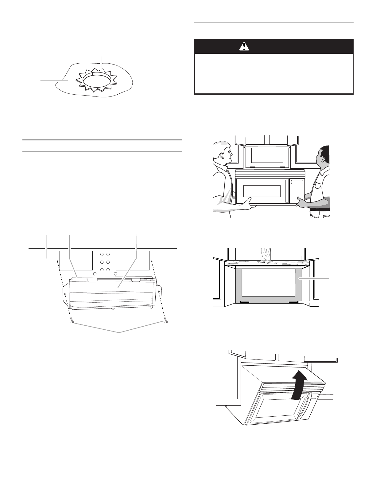
5. Cut the 1¹⁄₂" (3.8 cm) diameter hole at the circular shaded area
A
B
“G” on the template. This hole is for the power supply cord.
NOTE: If upper cabinet is metal, the supply cord bushing needs to
be installed around the supply cord hole, as shown.
B
A
Install the Microwave Oven
WARNING
Excessive Weight Hazard
Use two or more people to move and install
microwave oven.
Failure to do so can result in back or other injury.
A. Metal cabinet
B. Power supply cord bushing
6. Drill 3/8" (10 mm) holes at points “D” and “E” on the template.
These are for two 1/4-20 x 3" round-head bolts and washers
used to secure the microwave oven to the upper cabinet.
For Roof Venting Installation Only
7. Cut 3/4" (19 mm) hole at one corner of the shaded rectangular
area “F” on Upper Cabinet Template.
8. Using a keyhole saw, cut out the rectangular area.
Install Damper Assembly
(for wall venting only)
1. Check that damper blade moves freely, and opens fully.
2. Position the damper assembly on the back of the microwave
oven so that the damper blade opens away from the
microwave oven.
A B C
IMPORTANT: The control side of the unit is the heavy side.
Handle the microwave oven gently.
1. Place a washer on each 1/4-20 x 3" bolt and place inside
upper cabinet near the 3/8" (10 mm) holes.
2. Make sure the microwave oven door is closed and taped shut.
3. Using 2 or more people, lift microwave oven and hang it on
support tabs at the bottom of mounting plate.
NOTE: Do not grip or use the door or door handle during
installation.
D
A. Back of microwave oven
B. Damper assembly
C. Damper blade
D. Sheet metal screws
3. Secure damper assembly with 2 sheet metal screws.
A. Mounting plate
B. Support tabs
4. With front of microwave oven still tilted, thread power supply
cord through the power supply cord hole in the bottom of the
upper cabinet.
5. Rotate microwave oven up toward upper cabinet.
NOTE: If venting through the wall, make sure the damper
assembly fits easily into the vent tube in the wall cutout.
9
Page 10
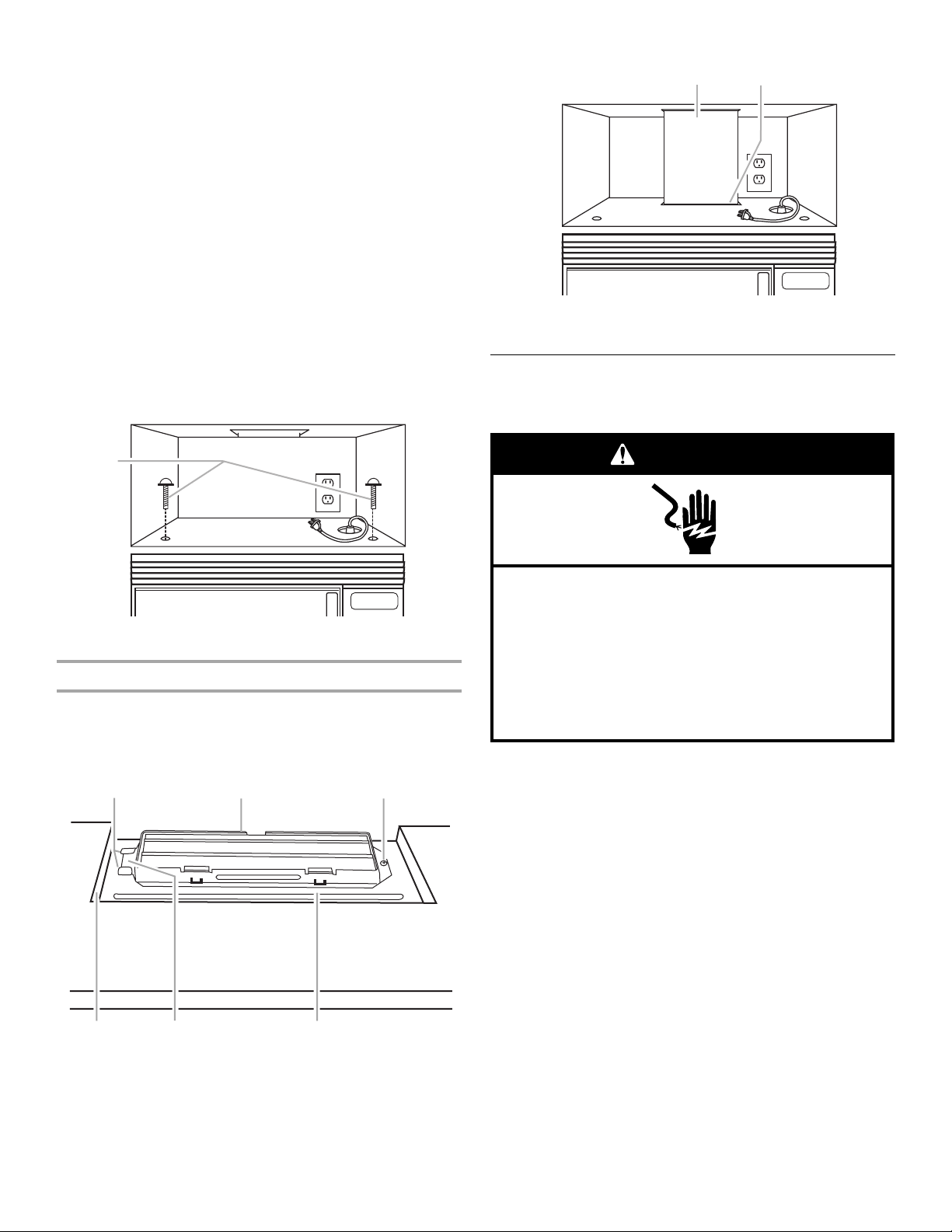
6. Push microwave oven against mounting plate and hold in
place.
NOTE: If microwave oven does not need to be adjusted, skip
steps 7-9.
7. If adjustment is required, rotate microwave oven downward.
Using 2 or more people, lift microwave oven off of mounting
plate, and set aside on a protected surface.
8. Loosen mounting plate screws. Adjust mounting plate and
retighten screws.
9. Repeat steps 3-6.
10. With the microwave oven centered, and with at least one
person holding it in place, insert bolts through upper cabinet
into microwave oven. Tighten bolts until there is no gap
between upper cabinet and microwave oven.
NOTES:
■ Some upper cabinets may require bolts longer or shorter than
3" (7.6 cm). Longer or shorter bolts are available at most
hardware stores.
■ Overtightening bolts may warp the top of the microwave oven.
To avoid warping, wood filler blocks may be added. The
blocks must be the same thickness as the space between the
upper cabinet bottom and the microwave oven.
2. Connect vent to damper assembly.
A B
A. Vent
B. Damper assembly (under vent)
Complete Installation
1. Refer to the Use and Care Guide for instructions on how to
install filters into your model.
A
A. Bolts
For Roof Venting Installation Only
1. Insert damper assembly through the cabinet cutout so that the
long tab of the damper assembly slides into the raised slot of
the damper plate. Then secure with sheet metal screw.
NOTE: The screw cannot be installed if the damper assembly is
not positioned as shown.
A B C
D E F
A. Raised tabs
B. Damper assembly
C. Sheet metal screw
D. Upper cabinet cutout
E. Long tab
F. Da m pe r pl a te
WARNING
Electrical Shock Hazard
Plug into a grounded 3 prong outlet.
Do not remove ground prong.
Do not use an adapter.
Do not use an extension cord.
Failure to follow these instructions can result in death,
fire, or electrical shock.
2. Plug microwave oven into grounded 3 prong outlet.
3. Reconnect power.
4. Check the operation of microwave oven by placing 1 cup
(250 mL) of water on the turntable, and programming a cook
time of 1 minute at 100% power. Test vent fan and exhaust by
operating the vent fan.
5. If the microwave oven does not operate:
■ Check that a household fuse has not blown, or that a
circuit breaker has not tripped. Replace the fuse or reset
the circuit breaker. If the problem continues, call an
electrician.
■ Check that the power supply cord is plugged into a
grounded 3 prong outlet.
■ See the Use and Care Guide for troubleshooting
information.
Installation is now complete.
Save Installation Instructions for future use.
10
Page 11
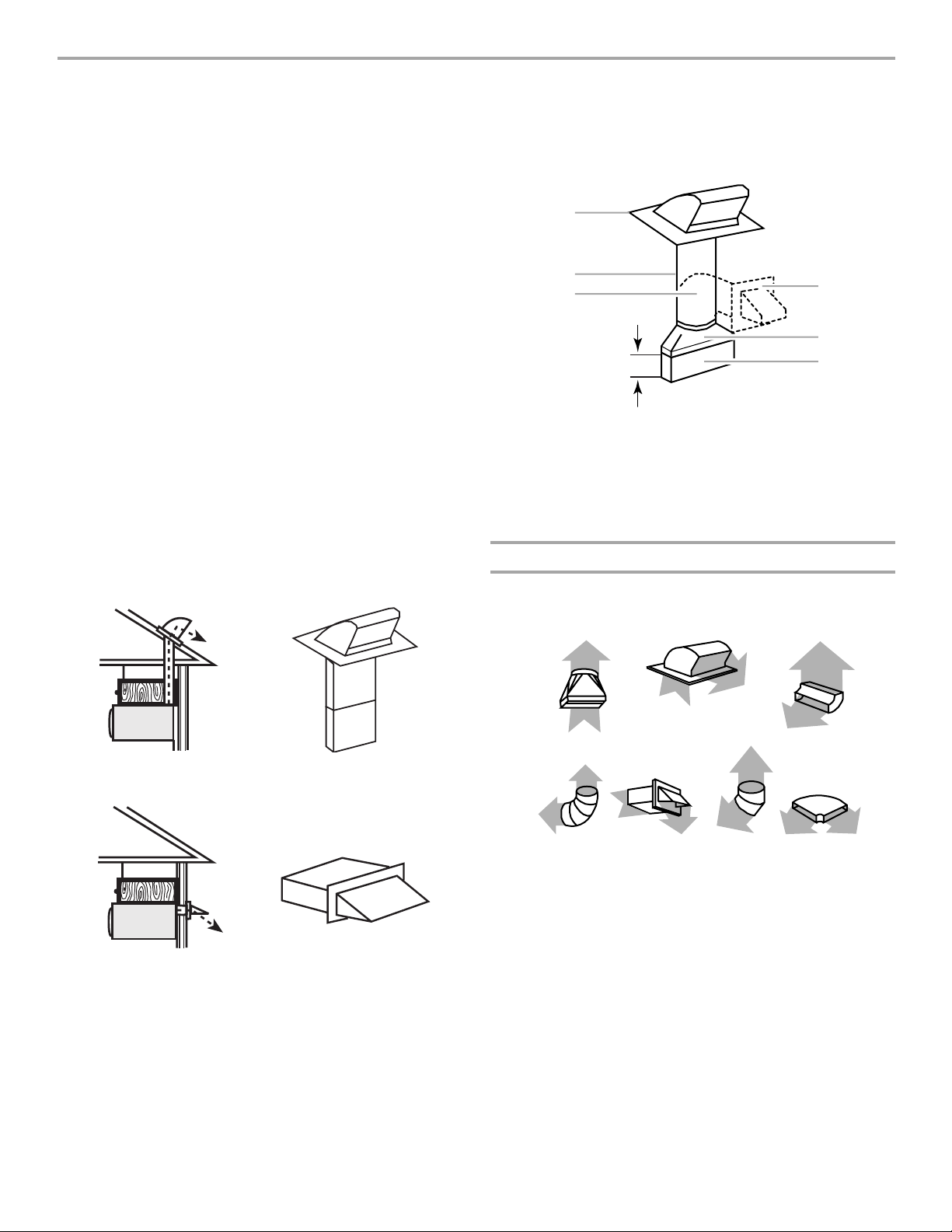
VENTING DESIGN SPECIFICATIONS
E
D
This section is intended for architectural designer and builder/
contractor reference only.
NOTES:
■ Vent materials needed for installation are not provided with
microwave hood.
■ We do not recommend using a flexible metal vent.
■ To avoid possible product damage, be sure to vent air outside,
unless using recirculation installation. Do not vent exhaust air
into concealed spaces, such as spaces within walls or
ceilings, attics, crawl spaces or garages.
For optimal venting installation, we recommend:
■ using roof or wall caps that have back draft dampers
■ using a rigid metal vent
■ using the most direct route by minimizing the length of the
vent and number of elbows to provide efficient performance
■ using uniformly sized vents
■ using duct tape to seal all joints in the vent system
■ using caulking compound to seal exterior wall or roof opening
around cap
■ not installing 2 elbows together, for optimal hood performance
If venting through the wall, be sure that there is proper clearance
within the wall for the damper to open fully.
If venting through the roof, and rectangular to round transition is
used, be sure there is at least 3" (7.6 cm) of clearance between
the top of the microwave oven and the transition piece. See
“Rectangular to Round Transition” illustration.
Rectangular to Round Transition
NOTE: The minimum 3" (7.6 cm) clearance must exist between
the top of the microwave oven and the rectangular to round
transition piece so that the damper can open freely and fully.
A
B
C
3" (7.6 cm)
A. Roof cap
B. 6" (15.2 cm) min. diameter round vent
C. Elbow (for wall venting only)
D. Wall cap
¹⁄₄
" x 10" to 6" (8.3 x 25.4 cm to 15.2 cm)
E. 3
rectangular to round transition piece
F. Vent extension piece, at least 3" (7.6 cm) high
F
Recommended Standard Fittings
The following length equivalents are for use when figuring vent
length. See the examples in “Recommended Vent Length.”
A B C
Roof venting Roof cap
Wall venting Wall cap
D E F G
A. Rectangular to round transition piece: 3
(8.3 x 25.4 cm to 15.2 cm = 1.5 m)
B. Roof cap: 3
C. 90° elbow: 3
D. 90° elbow: 6" = 10 ft (15.2 cm = 3 m)
E. Wall cap: 3
F. 45° elbow: 6" = 5 ft (15.2 cm = 1.5 m)
G. 90° flat elbow: 3
¹⁄₄
" x 10" = 24 ft (8.3 x 25.4 cm = 7.3 m)
¹₄
" x 10" = 25 ft (8.3 x 25.4 cm = 7.6 m)
¹⁄₄
" x 10" = 40 ft (8.3 x 25.4 cm = 12.2 m)
¹⁄₄
" x 10" = 10 ft (8.3 x 25.4 cm = 3 m)
¹⁄₄
" x 10" to 6" = 5 ft
11
Page 12
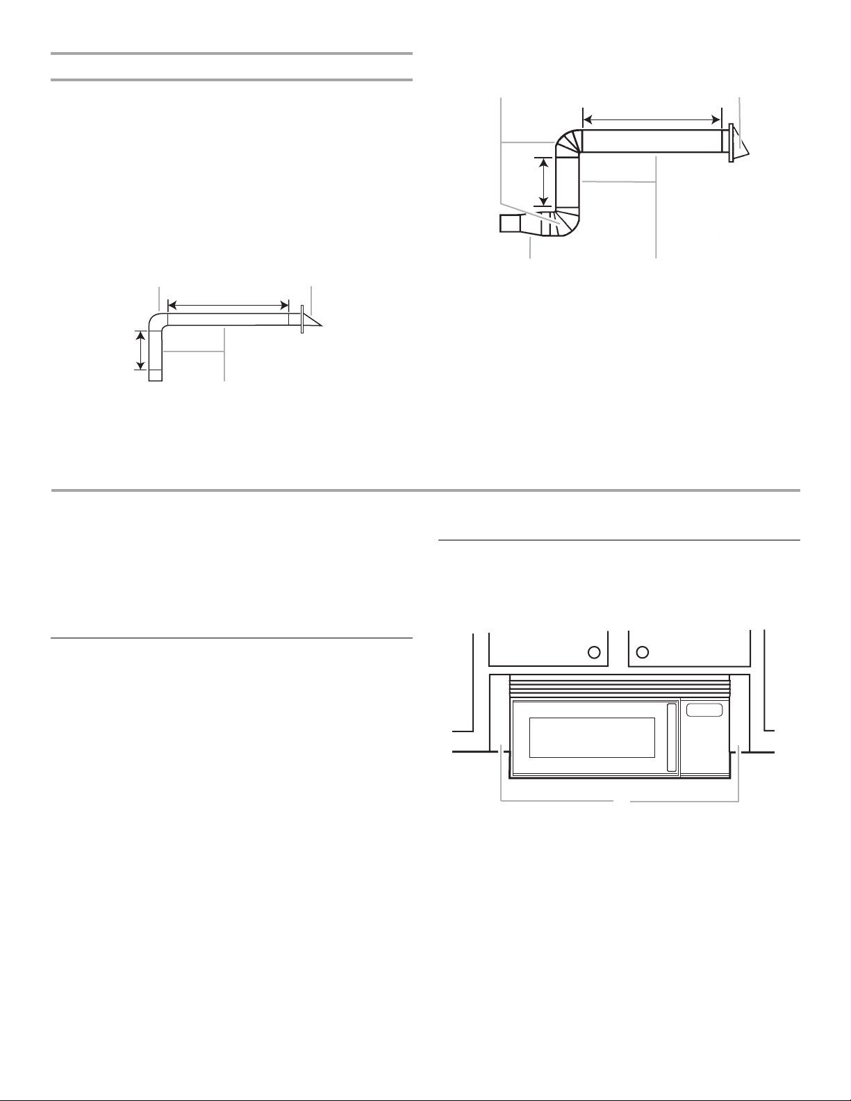
Recommended Vent Length
6" (15.2 cm) vent system = 73 ft (22.2 m) total
A 3¹⁄₄" x 10" (8.3 x 25.4 cm) rectangular or 6" (15.2 cm) round vent
should be used.
The total length of the vent system including straight vent,
elbow(s), transitions and wall or roof caps must not exceed the
equivalent of 140 ft (42.7 m) for either type of vent. See
“Recommended Standard Fittings” section for equivalent lengths.
For best performance, use no more than three 90° elbows.
To calculate the length of the system you need, add the equivalent
lengths of each vent piece used in the system. See the following
examples:
3¹⁄₄" x 10" (8.3 x 25.4 cm) vent system = 73 ft (22.2 m) total
A B
6 ft (1.8 m)
2 ft
(0.6 m)
C
A. One 3
B. 1 wall cap = 40 ft (12.2 m)
C. 2 ft (0.6 m) + 6 ft (1.8 m) straight = 8 ft (2.4 m)
¹⁄₄
" x 10" (8.3 x 25.4 cm) 90° elbow = 25 ft (7.6 m)
A B
6 ft (1.8 m)
2 ft
(0.6 m)
C D
A. Two 90° elbows = 20 ft (6.1 m)
B. 1 wall cap = 40 ft (12.2 m)
C. 1 rectangular to round transition piece = 5 ft (1.5 m)
D. 2 ft (0.6 m) + 6 ft (1.8 m) straight = 8 ft (2.4 m)
If the existing vent is round, a rectangular to round transition piece
must be used. In addition, a rectangular 3" (7.6 cm) extension vent
between the damper assembly and rectangular to round transition
piece must be installed to keep the damper from sticking.
ASSISTANCE
Call your authorized dealer or service center. When you call, you
will need the microwave oven model number and serial number.
Both numbers can be found on the model and serial number
plate, which is located behind the microwave oven door on the
front frame of the microwave oven.
If you need additional assistance, call us at our toll free number
listed in the Use and Care Guide, or visit us on the Web.
Replacement Parts
If any of the installation hardware needs to be replaced, call us at
our toll free number listed in the Use and Care Guide, and
reference the appropriate part number listed here.
Damper Assembly
Part Number 8206556
Mounting Plate
Part Number 8206315
Upper Cabinet Template
Part Number 8205924
Mounting Screw Kit (includes
parts A-F in “Parts Supplied”
section)
Part Number 8206554
Accessories
Filler Panel Kits are available from your dealer to use when
installing this microwave oven in a 36" (91.4 cm) or 42" (106.7 cm)
wide opening. The filler panels come in pairs. Each panel is 3"
(7.6 cm) wide.
A
A. Filler panels
Filler Panel Kit Number 8171336
8171337
8171338
8171339
99403
White
Black
Biscuit
Stainless Steel
Almond
8206327
© 2006.
All rights reserved.
See your authorized dealer or service center for details.
4619-656-03054
Printed in China
3/06
 Loading...