

Page 1
WHIRLPOOL
SELF-CLEANING
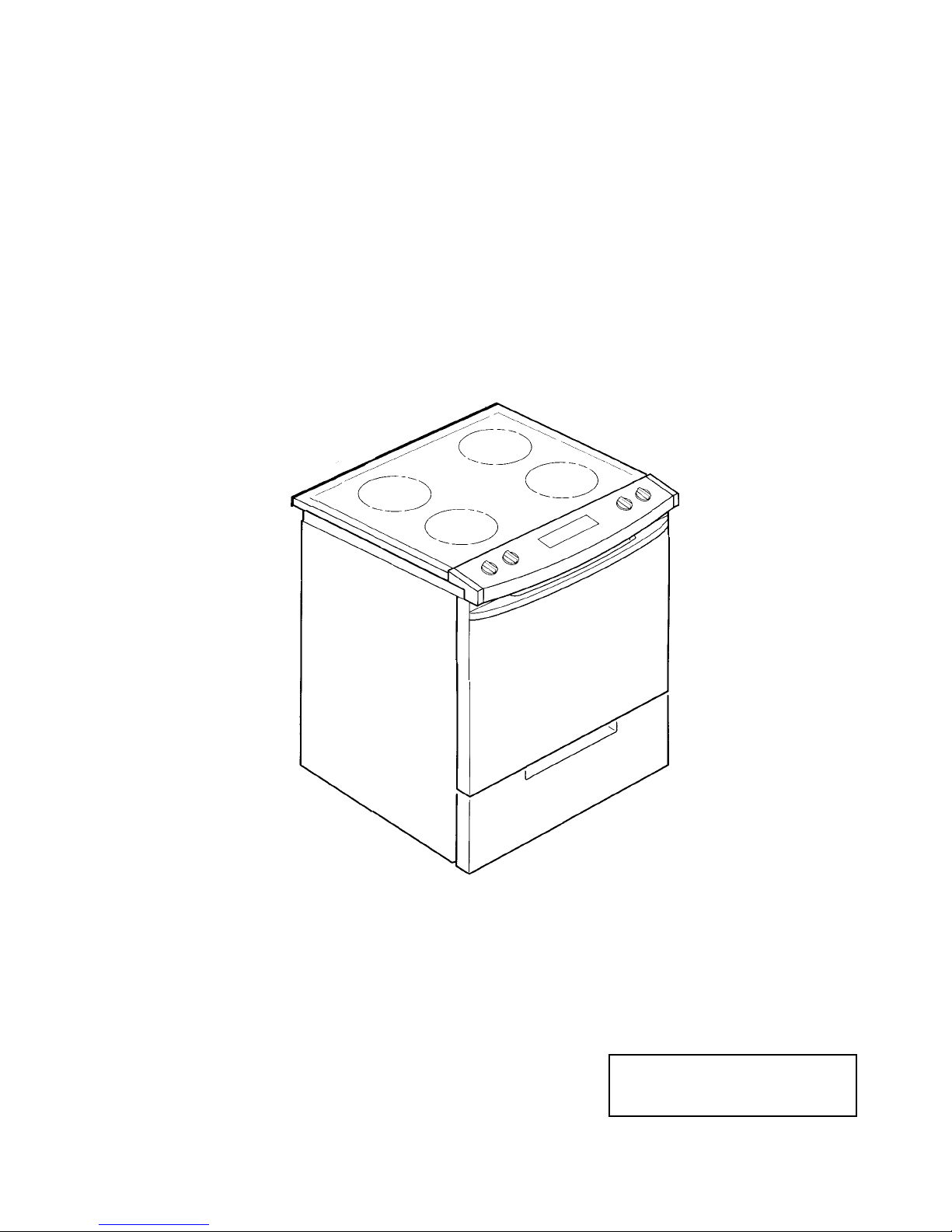
SLIDE-IN ELECTRIC RANGES
JOB AID
Part No. 4322525
Page 2

FORWARD
This Job Aid, “Self-Cleaning Slide-In Electric Ranges,” (Part No. 4322525), provides the technician with information on the installation, operation, and service of Whirlpool Self-Cleaning SlideIn Electric Ranges. It is to be used as a training Job Aid and Service Manual. For specific information on the model being serviced, refer to the “Use and Care Guide,” or “Tech Sheet” provided with
the range.
The Wiring Diagrams and Strip Circuits used in this Job Aid are typical and should be used for
training purposes only. Always use the Wiring Diagram supplied with the product when servicing
the unit.
GOALS AND OBJECTIVES
The goal of this Job Aid is to provide detailed information that will enable the service technician to
properly diagnose malfunctions and repair Self-Cleaning Slide-In Electric Ranges.
The objectives of this Job Aid are to:
• Understand and follow proper safety precautions.
• Successfully troubleshoot and diagnose malfunctions.
• Successfully perform necessary repairs.
• Successfully return the range to proper operational status.
WHIRLPOOL CORPORATION assumes no responsibility for any repair
made on our products by anyone other than Authorized Factory Service
Technicians.
Copyright 1999, Whirlpool Corporation, Benton Harbor, MI 49022
- ii -
Page 3

Table of Contents
PAGE
SPECIFICATIONS .................................................................................................................. 1-1
INSTALLATION HIGHLIGHTS................................................................................................ 2-1
Electrical Requirements ..................................................................................................... 2-1
Connecting The Range To An Electrical Supply................................................................ 2-3
Moving The Range ............................................................................................................ 2-6
PRODUCT OPERATION ........................................................................................................ 3-1
Air Flow — Rear Panel ...................................................................................................... 3-1
Cooling Fan Air Flow ......................................................................................................... 3-2
The Bimetal Switches ........................................................................................................ 3-3
The Surface Element Limiter ............................................................................................. 3-4
The Door Lock Solenoid & Door Latch Switch................................................................... 3-5
How The Self-Clean Cycle Works ..................................................................................... 3-6
COMPONENT ACCESS ......................................................................................................... 4-1
Component Locations ........................................................................................................ 4-1
Removing The Electronic Oven Control & The Control Panel ........................................... 4-2
Removing An Element Control (Infinite Switch) & A Surface Indicator Light ..................... 4-4
Removing A Bimetal Switch............................................................................................... 4-6
Removing The Ceran Glass Maintop................................................................................. 4-7
Removing A Surface Element & Hot Surface Indicator Light Assembly ............................ 4-8
Removing The Oven Bake & Broil Elements ................................................................... 4-10
Removing The Oven Light Assembly .............................................................................. 4-12
Removing The Oven Door Gasket................................................................................... 4-13
Removing The Oven Light Switch ................................................................................... 4-14
Removing The Cooling Fan ............................................................................................. 4-16
Removing The Oven Temperature Sensor &
The Door Latch Assembly Components ....................................................................... 4-18
Removing The Oven Door Glass ..................................................................................... 4-20
Removing The Outer Oven Glass.................................................................................... 4-22
Removing The Inner Oven Glass .................................................................................... 4-23
COMPONENT TESTING ........................................................................................................ 5-1
DIAGNOSIS & TROUBLESHOOTING.................................................................................... 6-1
WIRING DIAGRAMS & STRIP CIRCUITS.............................................................................. 7-1
TECH TIPS ............................................................................................................................. 8-1
- iii -
Page 4

WHIRLPOOL MODEL & SERIAL NUMBER DESIGNATIONS
MODEL NUMBER
MODEL NUMBER
INTERNATIONAL SALES IND.
OR MARKETING CHANNEL
IF PRESENT
PRODUCT GROUP:
R = ELECTRIC RANGES
S = GAS RANGES
G = WHIRLPOOL GOLD RANGE
PRODUCT IDENTIFICATION:
A = ACCESSORY K = KITS
B = BUILT-IN M = MV COMBO
C = COOKTOP S = SET-IN
E = EYE-LEVEL W = SLIDE-IN GAS
F = FREESTANDING Y = SLIDE-IN ELECTRIC
H = HOODS
MODEL SIZE:
3 = 30" SLIDE-IN
4 = 40" SLIDE-IN
5 = 36" SLIDE-IN
6 = 30" SET-IN RANGES
OVEN TYPE:
0 THRU 3 = STANDARD PORCELAIN
4 THRU 9 = PYROLYTIC SELF-CLEAN
FEATURE / VARIATIONS:
ELECTRIC
0, 1, 2, 5, 7 = COIL ELEMENTS
4 = STANDARD PATTERN CERAMIC
6, 8, 9 = DELUXE PATTERN CERAMIC
GAS
0, 1, 2, 3, 4, 6 = OPEN BURNER
5 & 7 = SEALED BURNER
DOOR TYPE:
B = SOLID BLACK GLASS
L = LARGE WINDOW
O = METAL OVEN DOOR
P = STANDARD WINDOW GLASS
FEATURE CODE:
E = ELECTRONIC IGNITION (GAS ONLY)
S = STANDING IGNITION (GAS ONLY)
C = COLOR COORDINATED GLASS (BEFORE 1998)
X = NOT DEFINED
YEAR OF INTRODUCTION:
G = 1998 H = 1999 J = 2000
COLOR CODE:
B = BLACK W = WHITE
N = ALMOND Z = ALMOND ON ALMOND
Q = WHITE ON WHITE
GY3 96LXG Q
SERIAL NUMBER
SERIAL NUMBER X H 0 7 1 2 3 4 5
OXFORD
YEAR OF INTRODUCTION
H = 1998, J = 1999, K = 2000
WEEK OF PRODUCTION (7th WEEK)
PRODUCT SEQUENCE NUMBER
- iv -
Page 5
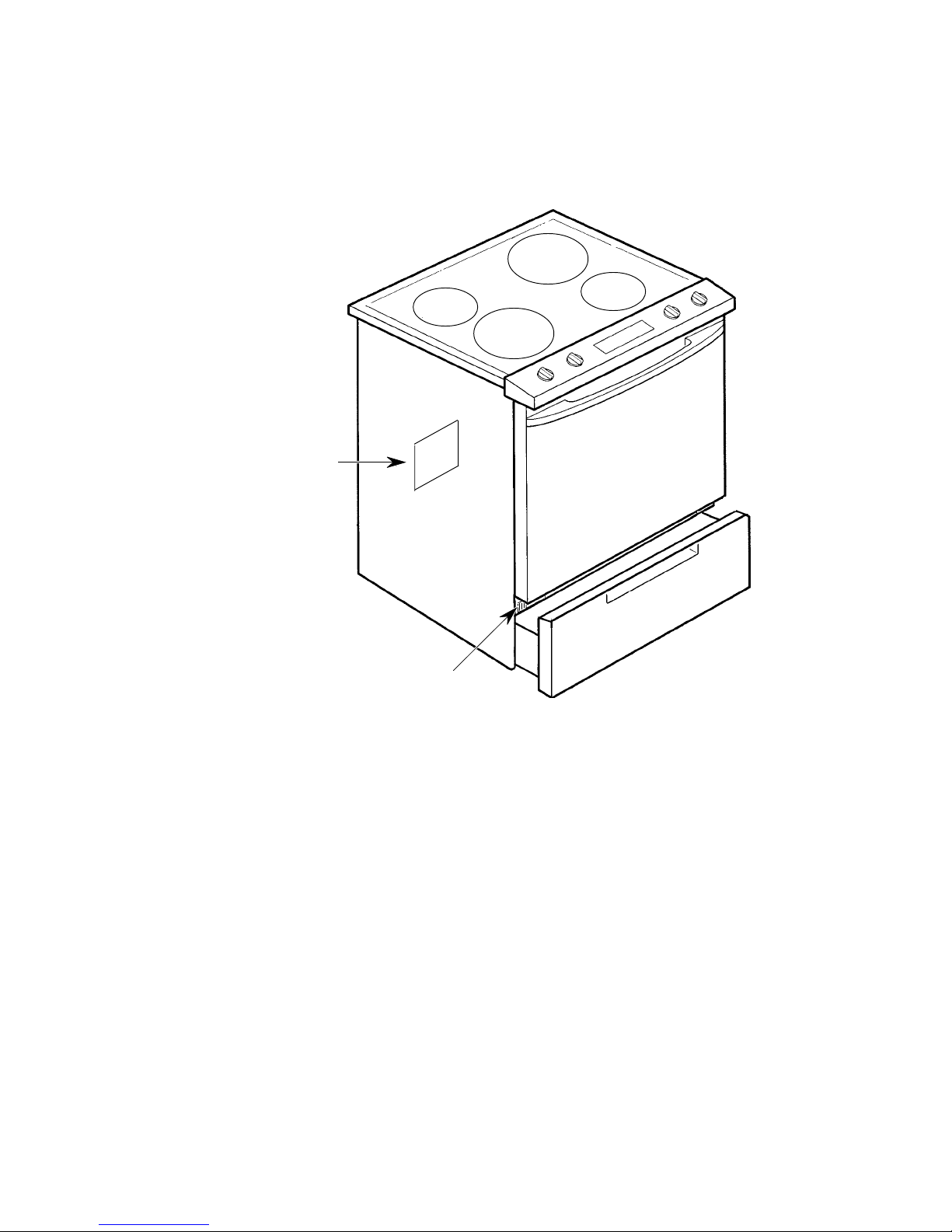
MODEL & SERIAL NUMBER LABEL
AND WIRING DIAGRAM LOCATIONS
The Model/Serial Number label and Wiring Diagram locations are shown below.
WIRING DIAGRAM
(on back cover)
MODEL/SERIAL
NUMBER LABEL
(behind top left side
of storage drawer)
- v -
Page 6

IMPORTANT SAFETY INFORMATION
Your safety and the safety of others is very important.
Important safety messages have been provided in this Job Aid. Always read and obey all safety
messages.
This is the safety alert symbol.
This symbol alerts you to hazards that can kill or hurt you and others.
All safety messages will be preceded by the safety alert symbol and the word
“WARNING.”
All safety messages will identify the hazard, tell you how to reduce the chance of injury, and tell
you what can happen if the instructions are not followed.
- vi -
Page 7
SPECIFICATIONS
Brand Whirlpool Whirlpool ( Gold) Whirlpool ( Gold)
US ELECTRIC MODEL # RS310PXG W/N GY395LXG Q/Z/B GY396LXG Q/Z/B
CANADIAN ELECTRIC MODEL # --- YGY395LXG Q/Z YGY396LXG Q/B
GENERAL INFORMATION
Cleaning System Std. Clean Self Clean Self Clean
Burner Type Coil Coil Radiant
Drip Pans or Glass Pattern Chrome Porcelain Q Style
Oven Controls TOD/Timer EZ300 EZ300
DIMENSIONS
Height to Maintop 36 " 36" 36 "
Depth - Overall 24.5" 24.5" 24.5"
Door Swing 21.75" 21.75" 21.75"
Depth with Handle 26.75" 26.75" 26.75"
Approx Shipping Weight 180 lbs 180 lbs 180 lbs
CONTROL PANEL FEATURES
Control Panel Glass Color Blk - Glass Wht/Alm/Blk - Glass Wht/Alm/Blk - Glass
Control Panel Color Black Wht/Alm/Blk Wht/Alm/Blk
Panel Construction/Shape Glass-square Glass-square Glass-square
Oven Control Location Center Center Center
Oven Controls TOD/Timer EZ 300 EZ 300
Oven Light US Yes-manual rocker Yes-in control Yes-in control
Oven Light CND Yes-manual rocker Yes-manual rocker Yes-manual rocker
Oven Heating Indicator Light Mini-Red (1) in Oven Control in Oven Control
Surface Unit Indicator Light Mini Red (2) Mini Red (2) Mini Red (2)
Surface Unit Controls Inf Detent Hi/Off Inf Detent Hi/Off Inf Detent Hi/Off
COOKTOP FEATURES
Cooktop Type Porcelain Porcelain Ceran
Drip pans Chrome Porcelain Q Style
Burner Type Coil Coil Radiant
Burner Configuration #REF! #REF! 4 Radiant
R. Front (240V) 6"-1500W 6"-1500W
L. Front (240V) 8"-2400W 8"-2600W
R. Rear (240V) 6"-1500W 6"-1100W
L. Rear (240V) 8"-2400W 8"-2600W
Hot Surface Indicator None None 4
OVEN FEATURES
Oven Type Std. Clean Self Clean Self Clean
Broil Element 2500W- 4 pass 3000W 6 pass 3000W 6 pass
Bake Element 2500w 2500w 2500w
Top Heat No Yes Yes
Accubake System No Yes Yes
Broil Pan - Storage Rails No Yes Yes
Auto Oven Light No Yes Yes
Manual Oven Light Yes-manual rocker Auto Auto
Lower Storage Drawer Yes Yes Yes
LITERATURE
Tech Sheets/Wiring Diagrams Yes Yes Yes
OTHER SPECIFICATIONS
UL/CSA approval Yes Yes Yes
Anti-Tip Device w/ Unit Floor Bracket Floor Bracket Floor Bracket
7"-1700W
9"-2400W
8"-2100W
6"-1400W
1-1
Page 8

— NOTES —
1-2
Page 9
INSTALLATION HIGHLIGHTS
ELECTRICAL REQUIREMENTS
A four-wire or three-wire, single-phase, 120/
WARNING
Electrical Shock Hazard
Turn power supply off before connecting
wires.
Use 8-gauge solid copper wire.
Electrically ground the range.
Failure to follow these instructions can result in death, fire, or electrical shock.
If codes permit and a separate ground wire
is used, it is recommended that a qualified
electrician determine that the ground path
and wire gauge are in accordance with local
codes.
Do not ground to a gas pipe.
Check with a qualified electrician if you are
not sure whether the range is properly
grounded.
Do not have a fuse in the neutral or ground
circuit.
The range must be connected with copper
wire only.
Wiring diagrams are provided in Section 7 of
this Job Aid.
240-volt, 60-Hz; 50-amp, AC-only, electrical
supply (or four-wire or three-wire 120/208-volt
if specified on the model/serial rating plate) is
required on a separate 50-ampere circuit, fused
on both sides of the line. A time-delay fuse or
circuit breaker is recommended. The model/
serial rating plate is located on the oven frame
behind the storage drawer panel (see page v).
Wire sizes and connections must conform to
the requirements of the National Electrical
Code, ANSI/NFPA 70—latest edition*, and all
local codes and ordinances for the kilowatt rating of the range.
This range should be connected directly to the
fused disconnect or circuit breaker box through
flexible, armored or nonmetallic sheathed, copper cable (with ground wire). Locate the junction box to allow two to three feet of slack in
the line so that the range can be moved if servicing is ever necessary. Do Not cut the conduit. A U.L.-listed conduit connector must be
provided at each end of the power supply cable
(at the range and at the junction box).
This range is manufactured with a white (neutral) power wire and a cabinet-connected bare
ground wire twisted together.
Remove the junction box cover.
Connect the range cable to the junction box
through a U.L.-listed conduit connector. Complete the electrical connection according to local codes and ordinances.
* National Fire Protection Association
Batterymarch Park
Quincy, Massachusetts 02269
2-1
Page 10
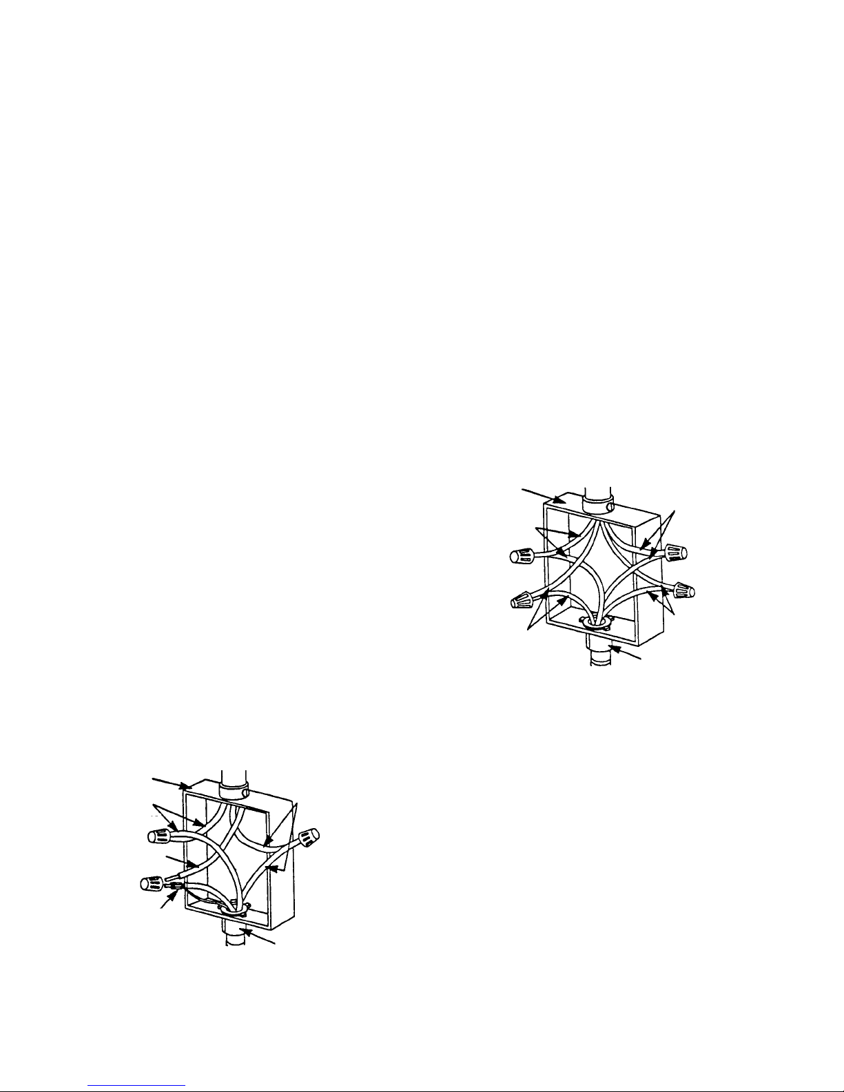
If connecting to a four wire electrical system, do not connect the cabinet-ground
conductor to the white (neutral) junction
box wire (see Figure 2-2).
Where local codes do not permit connecting the cabinet-ground conductor to the
white (neutral) junction box wire (Figure
2-2):
1. Disconnect the power supply.
2. Separate the green, (or bare), and the
white appliance cable wires.
3. Connect the white range cable wire to the
white (neutral) wire in the junction box.
4. Connect the two black wires together with
a twist-on connector.
5. Connect the two red wires together with a
twist-on connector.
6. Connect the green range wire to the green
ground wire in the junction box.
7. Replace the junction box cover.
Where local codes permit connecting the
cabinet-ground conductor to the white
(neutral) junction box wire (Figure 2-1):
1. Disconnect the power supply.
2. Remove the junction box cover.
3. Connect the green and white range cable
wires and the white (neutral) wire in the
junction box together with a twist-on connector.
4. Connect the two black wires together with
a twist-on connector.
5. Connect the two red wires together with a
twist-on connector.
6. Replace the junction box cover.
1. Disconnect the power supply.
2. Separate the green and white appliance
cable wires.
3. Connect the white range cable wire to the
white (neutral) wire in the junction box with
a twist-on connector.
4. Connect the two black wires together with
a twist-on connector.
5. Connect the two red wires together with a
twist-on connector.
6. Connect the green or bare ground wire
from the range cable to a ground wire in
the junction box.
7. Replace the junction box cover.
cable from
junction
box
red
wires
bare or green
wires
power supply
cable from
range
white
wires
black
wires
U.L.-listed
conduit
connector
Figure 2-2
cable from
junction
box
red
wires
white
wire
bare or green
wire
power supply
cable from
range
U.L.-listed
connector
Figure 2-1
black
wires
conduit
2-2
Page 11
CONNECTING THE RANGE
TO AN ELECTRICAL SUPPLY
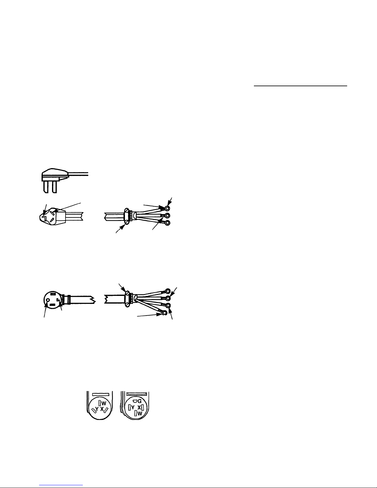
IMPORTANT: Use a new 40-ampere power
supply cord. Local codes may permit the use
of a U.L.-listed, 250-volt, 40-ampere range
power supply cord (pigtail). The power supply
cord should be Type SRD or SRDT, and be at
least 4-feet long. The wires that connect to the
range must end with ring terminals. A 3/
"
(1.9
4
cm), U.L.-listed strain relief must be installed
where the power supply cord connects to the
range (see Figure 2-3).
3-WIRE POWER SUPPLY CORD
NEMA 10-50P
NEUTRAL
3/4" (1/9 cm) U.L.-LISTED
(MOBILE HOME OR OTHER 4-WIRE INSTALLATIONS)
3/4" (1/9 cm) U.L.-LISTED
NEUTRAL
GROUNDING PRONG
THIS BLADE CONNECTED
TO THIS CONDUCTOR
NEUTRAL
STRAIN RELIEF
4-WIRE POWER SUPPLY CORD
NEMA 10-50P
STRAIN RELIEF
GROUNDING WIRE
(GREEN OR GREEN-YELLOW)
(WHITE OR CENTER)
NEUTRAL (WHITE)
RING TERMINALS
Figure 2-3
Power Supply Cords
The power supply cord must have three No.-10
copper wires to match a 3-wire receptacle of NEMA
Type 10-50R. (See Figure 2-4).
3-wire wall
receptacle
(10-50R)
4-wire wall
receptacle
(14-50R)
Figure 2-4
AC Receptacles
This range is manufactured with ground connected to cabinet for mobile home, or other 4wire installations. The ground must be revised
so the green grounding wire of the four-wire
power cord is connected to the cabinet.
For a 4-wire receptacle (NEMA Type 14-50R,
shown in Figure 2-4), a matching U.L.-listed,
4-wire, 250-volt, 40-ampere, range power supply cord (pigtail) must be used. This cord contains four copper conductors with ring terminals on the appliance end, and terminates in a
NEMA Type 14-50P plug on the supply end.
The fourth (grounding) conductor must be identified by a green, or green/yellow cover, and
the neutral conductor by a white cover. The cord
should be Type SRD or SRDT with a U.L.-listed
strain relief, and be at least 4-feet long.
The MINIMUM conductor sizes for the copper
4-wire power supply cord are:
• 40-ampere circuit
• 2) #8 conductors
• 1) #10 white neutral
• 1) #8 green grounding
The range can also be connected directly to a
fused disconnect, or to a circuit breaker box,
through flexible, armored or nonmetallic
sheathed, copper cable (with a grounding wire).
Do not use 2-wire cable with a bare grounding
wire. All current-carrying wires must be insulated. A U.L.-listed conduit connector must be
provided at each end of the power supply cord
(at the appliance and at the junction box). USE
ONLY 8-GAUGE SOLID COPPER WIRE. DO
NOT USE ALUMINUM WIRE. Allow 2- or 3feet of slack in the line so the range can be
moved if servicing is ever necessary.
IMPORTANT: The metal chassis of the range
must be earth-grounded so that the control
panel will operate. If the chassis is not earthgrounded, none of the keypads will operate.
Check with a qualified electrician if you are in
doubt as to whether the range is earthgrounded.
2-3
Page 12
WARNING
Electric Shock Hazard
Do not use 2-wire cable with a bare
grounding wire. All current -carrying wires
must be insulated.
Failure to follow these instructions could
result in fire, electrical shock, or death.
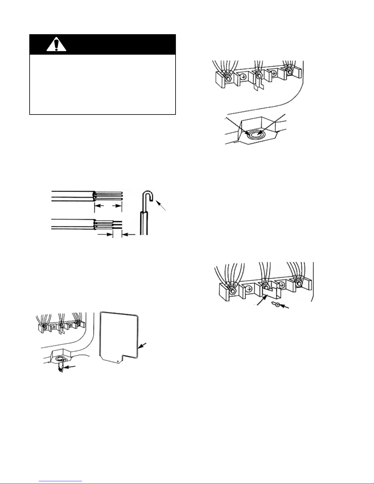
To install the power supply cord to the terminal
block screws on the back of the range, perform the following steps.
4. Attach a U.L.-listed conduit connector to
the knockout opening, but do not remove
the knockout (see Figure 2-7).
Do Not Remove
Knockout
Conduit
Connector
Opening
1. Turn off the power supply.
2. If the power supply cord does not have
eyelets installed on the leads, prepare the
leads, as shown in Figure 2-5.
3"
(7.6 cm) Hooked
Lead
1" (2.5 cm)
Figure 2-5
Preparing The Lead Ends
3. Remove the terminal block cover from the
back of the range, and the brass terminal
nuts that are attached to the knockout (see
Figure 2-6).
Terminal
Block
Cover
Figure 2-7
Mounting The Conduit Connector
5. Slide the lead end of the power supply
cord through the conduit connector and
tighten the strain relief clamp. Make sure
that you allow enough slack in the cord so
you can easily connect the lead ends to
the terminal block screws (see Figure
2-8).
6. Remove the grounding link screw from the
range frame (see Figure 2-8).
Grounding Link
Grounding
Link Screw
Figure 2-8
Removing The Grounding Link Screw
Brass
Terminal Nuts
Figure 2-6
Removing The Terminal Block Cover & Nuts
2-4
Page 13
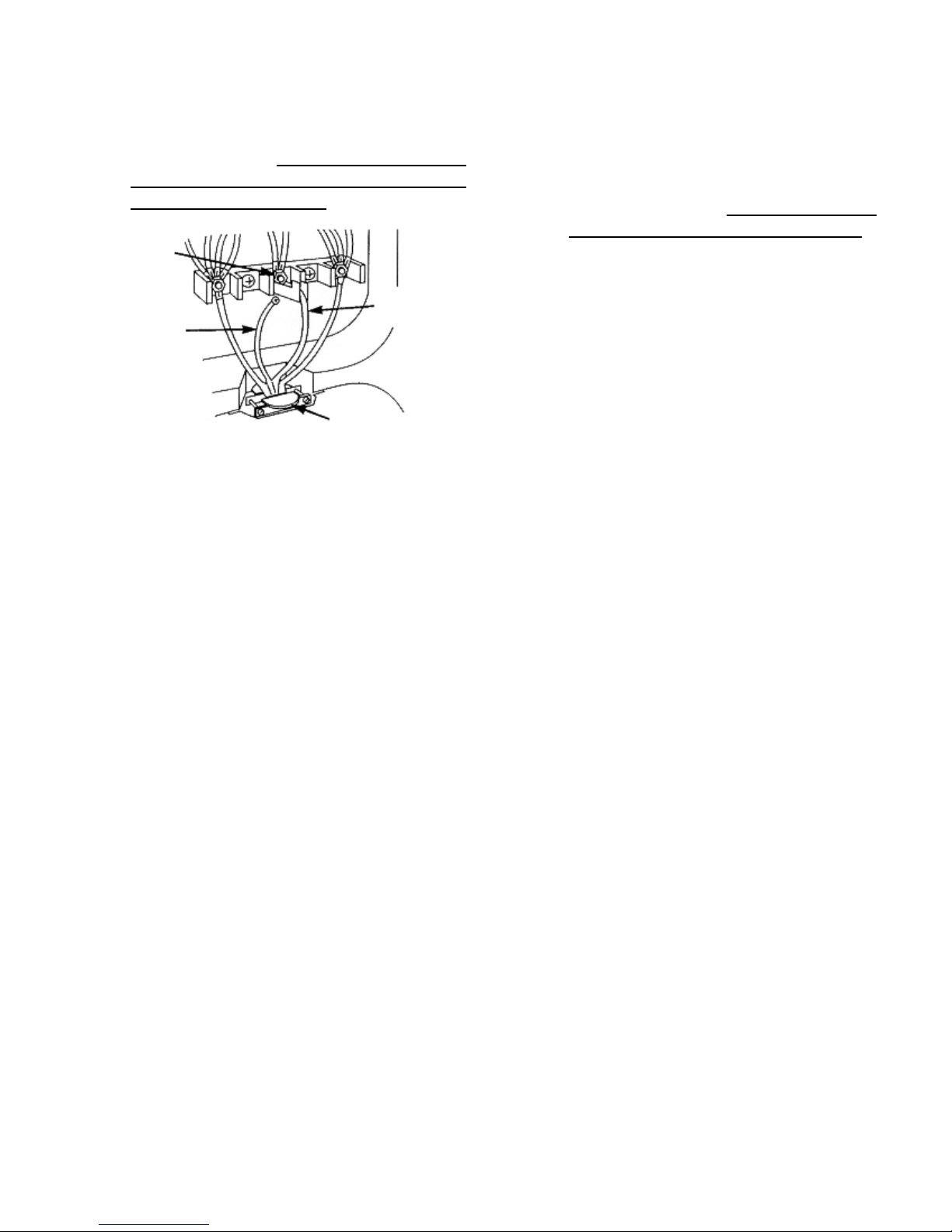
7. Mount the green ground lead from the
power cord to the grounding link with the
grounding link screw you just removed
(see Figure 2-9). This lead must be at-
tached first and must not contact any
of the other terminals.
Silver
Terminal
White
Green
(ground)
Lead
(neutral)
Lead
Strain Relief
Figure 2-9
Connecting The Leads
8. Using the brass terminal nuts you removed in step 3, connect the power supply
cord lead ends to the terminal screws as
follows (see Figure 2-9):
a) White (neutral) lead to the center (sil-
ver) terminal screw. This lead must be
connected to the center terminal.
b) Remaining two leads to the outer
screw terminals.
9. Make sure that the conduit strain relief is
tight, then mount the terminal block cover
to the range with the hardware you removed in step 3.
2-5
Page 14
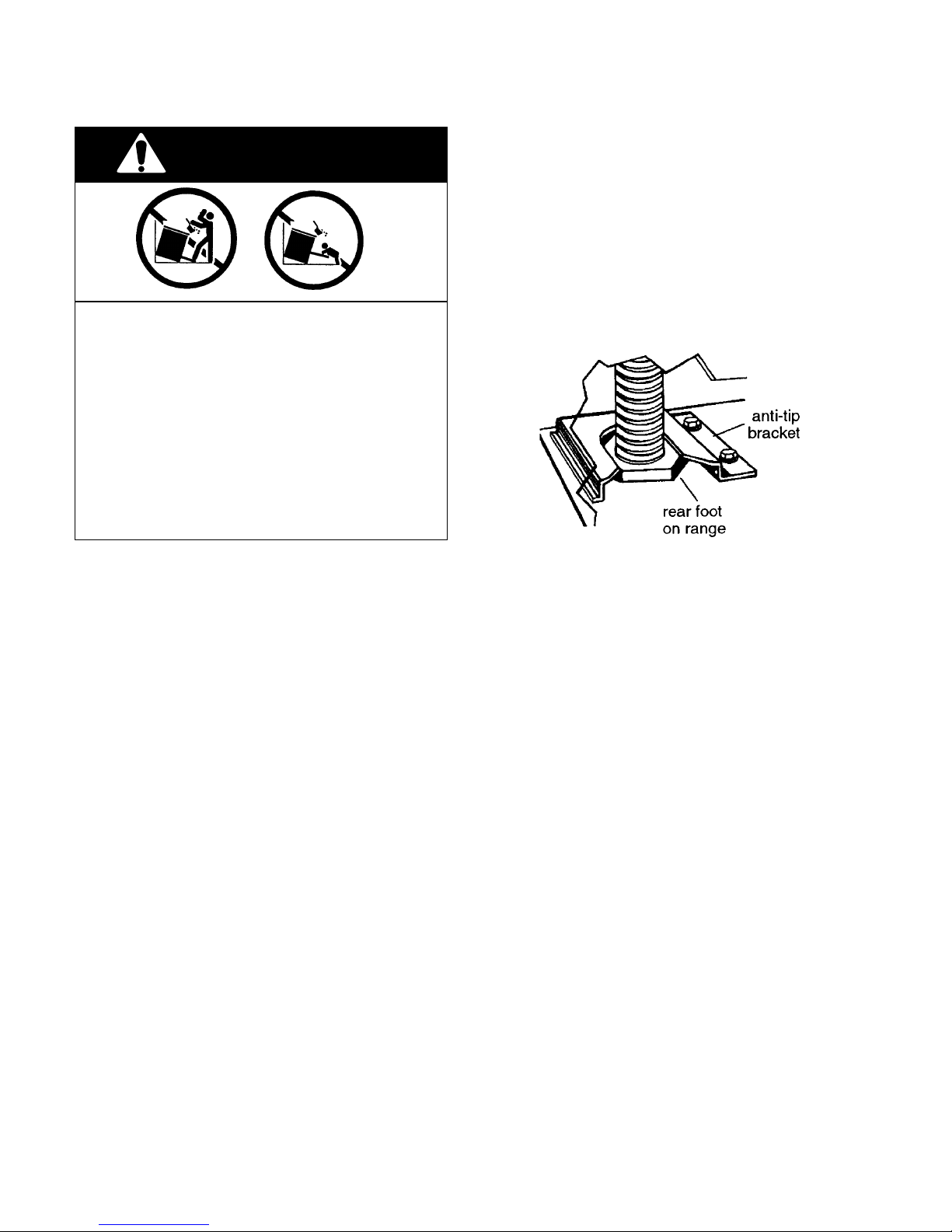
MOVING THE RANGE
WARNING
Tip-Over Hazard
A child or adult can tip the range and be
killed.
Connect anti-tip bracket to rear range foot.
Reconnect the anti-tip bracket, if the range
is moved.
Failure to follow these instructions can result in death or serious burns to children
and adults.
Before moving the range, slide it onto a piece
of cardboard, or hardboard, to prevent damaging the floor covering, and perform the following steps:
1. Disconnect the electrical supply.
2. Slide the range forward and disengage
the foot with the anti-tip bracket. IMPORTANT: Make sure the anti-tip bracket is
securely attached to floor.
3. Slide range back so the rear foot engages
in the anti-tip bracket.
4. Check to see that the range is level.
5. Reconnect the electrical supply cord.
2-6
Page 15
PRODUCT OPERATION
AIR FLOW — REAR PANEL
The electric range needs sufficient air to properly cool the oven. In addition, proper air flow
through the electric range also keeps the front
control panel from becoming too hot while the
elements are operating, and causing operational problems.
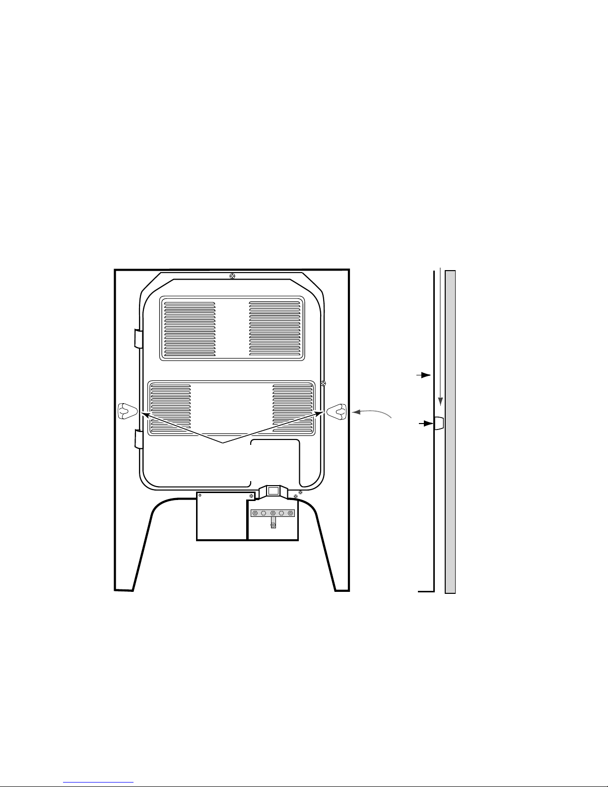
To help provide the proper air flow along the
back of the range, the rear panel of the range
has a spacer on each side toward the bottom
(see Figure 3-1). When the range is installed,
these spacers should just come in contact with
the surface of the wall. If they are accidentally
bent in, proper spacing will be lost, and the
oven will not heat properly. Also, the front control panel may become overly warm, and cause
the bimetal switches to trip, shutting down the
operation. If any of these problems occur, it is
most likely because of air flow restrictions.
AIRFLOW
REAR
PANEL
EXTRUDED
SPACERS
ON REAR PANEL
Figure 3-1
SPACER
WALL
SIDE VIEW
3-1
Page 16
COOLING FAN AIR FLOW
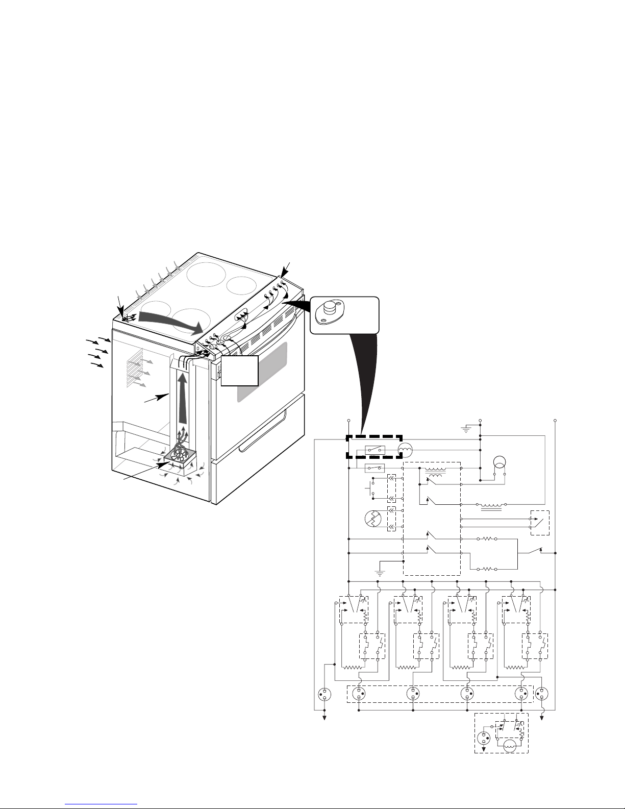
Refer to Figure 3-2 while you read this description.
The cooling fan is in series with the cooling fan
bimetal switch, which is located under the right
side of the control panel. When the temperature of the chassis reaches 40˚C (104˚F), the
bimetal switch closes, and turns on the cooling fan.
The cooling fan draws air from inside the base
of the cabinet. It forces the air up the air chan-
AIR FLOWS FROM
CONTROL PANEL
UNDER RANGE TOP
OVEN VENT FOR
OVEN EXHAUST
AIR FLOWS
INTO
REAR PANEL
LOUVERS
AIR INLETS
UNDER
CONTROL
PANEL
nel, which is located under the left side panel,
to the opening at the end of the control panel.
Air then flows across the chassis below the
control panel, and cools it. Air enters through
the series of holes in front of the range top,
flows beneath it, and exits to the outside
through slots in the rear panel. When the control panel chassis temperature drops below
40˚C (104˚F), the bimetal switch opens, and
turns the cooling fan off.
COOLING FAN
BIMETAL SWITCH
COOLING FAN
AIR CHANNEL
Figure 3-2
DOOR
LATCH SW.
DLB RELAY
V
1B
SURF
IND.
LIGHT
L2
R
R
R
L1
BK
BI - METAL SW FAN N.O.
YY
BI-METAL SW
AMBIENT N.C.
BK
DOOR
SW.
OVEN
TEMP
SENSOR
W
BK
BK
GND
BK
L2L1
P
LF
H1 H2
BK
2ABK2B
1A 1B
V
BU
SURF
IND.
LIGHT
LF
M
OVEN CONTROL
P4-3
TRANSFORMER
BK
Y
P3-3
OVEN LIGHT
RELAY
Y
P3-4
V
LATCH RELAY
P3-6
V
P3-7
P2-2
BROIL RELAY
P2-3
OR P6
P3-5
LR
H1 H2
Y
BAKE RELAY
L2L1
2AY2B
1A 1B
V
HOT SURFACE
LR
IND. LIGHTS
G
P
GND
W
W
DOOR LOCK
SOLENOID
1B
V
P
OVEN LT.
W
BU
R
RR
H1 H2
R
BU
RR
N.O.
COM
L2L1
2ABU2B
1A
P
P4-1
P4-4
P4-5
P3-1
P3-2
P2-1
P2-4
L1
H1 H2
BR
W
R
BR
BU
BU
V
R
RF
2ABR2B
1A
BU
BROIL ELEMENT
BAKE ELEMENT
L2
RF
3-2
N
SUR.
IND.
LIGHT
H2
N
INF.SWITCH
(OPTIONAL)
COIL ELEMENT
P
H1
N
L2
L1
Page 17
THE BIMETAL SWITCHES
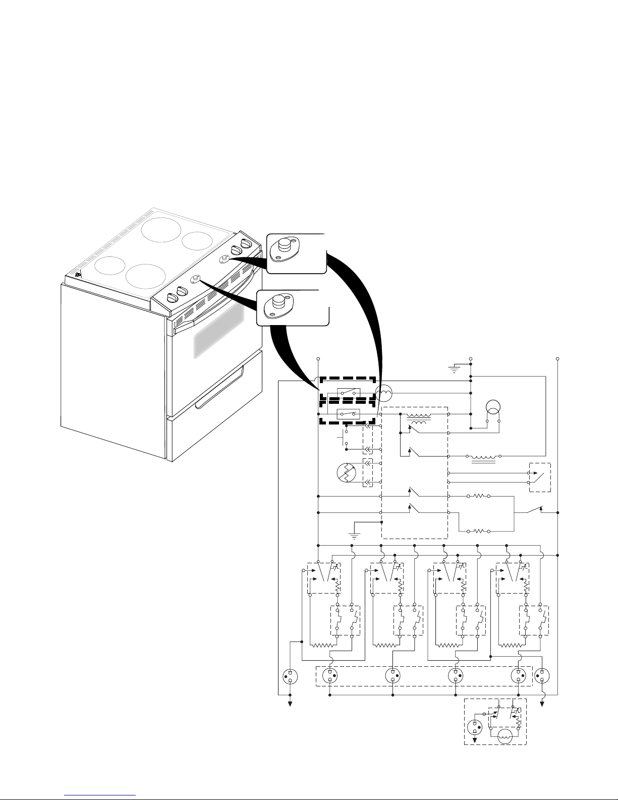
There are two bimetal switches on the electric
range. The switches operate as follows:
•
Ambient Bimetal Switch (N.C.)
(Inset #1)
der the left side of the control console.
It opens the L1 circuit to the electronic
control board if the console temperature
reaches 95˚C/203˚F.
—This switch is located un-
FAN BIMETAL
AMBIENT
BIMETAL SWITCH
Inset #2
COOLING
SWITCH
Inset #1
•
Cooling Fan Bimetal Switch (N.O.)
(Inset #2)
—This switch is located under the right side of the control console.
It turns the cooling fan on if the console
temperature reaches 40˚C/104˚F.
Figure 3-3
DOOR
V
1B
SURF
IND.
LIGHT
L2
R
R
R
L1
BK
BI - METAL SW FAN N.O.
YY
BI-METAL SW
AMBIENT N.C.
BK
DOOR
SW.
OVEN
TEMP
SENSOR
W
BK
BK
GND
BK
LF
H1 H2
BK
L2L1
2ABK2B
1A 1B
V
LF
P
BU
SURF
IND.
LIGHT
M
OVEN CONTROL
P4-3
Y
P3-3
Y
P3-4
V
P3-6
V
P3-7
P2-2
P2-3
OR P6
P3-5
LR
H1 H2
Y
TRANSFORMER
OVEN LIGHT
RELAY
LATCH RELAY
BROIL RELAY
BAKE RELAY
L2L1
2AY2B
1A 1B
V
HOT SURFACE
LR
IND. LIGHTS
BK
G
P
GND
W
OVEN LT.
W
W
N.O.
COM
BU
LATCH SW.
DLB RELAY
R
RR
H1 H2
R
BU
RR
L2L1
2ABU2B
1A
P
1B
P
P4-1
P4-4
P4-5
P3-1
P3-2
P2-1
P2-4
L1
RF
H1 H2
BR
BU
W
R
BR
BU
BU
BROIL ELEMENT
V
R
BAKE ELEMENT
L2
2ABR2B
1A
V
RF
DOOR LOCK
SOLENOID
N
3-3
SUR.
IND.
LIGHT
L2
L1
P
H1
N
H2
N
INF. SWITCH
(OPTIONAL)
COIL ELEMENT
Page 18
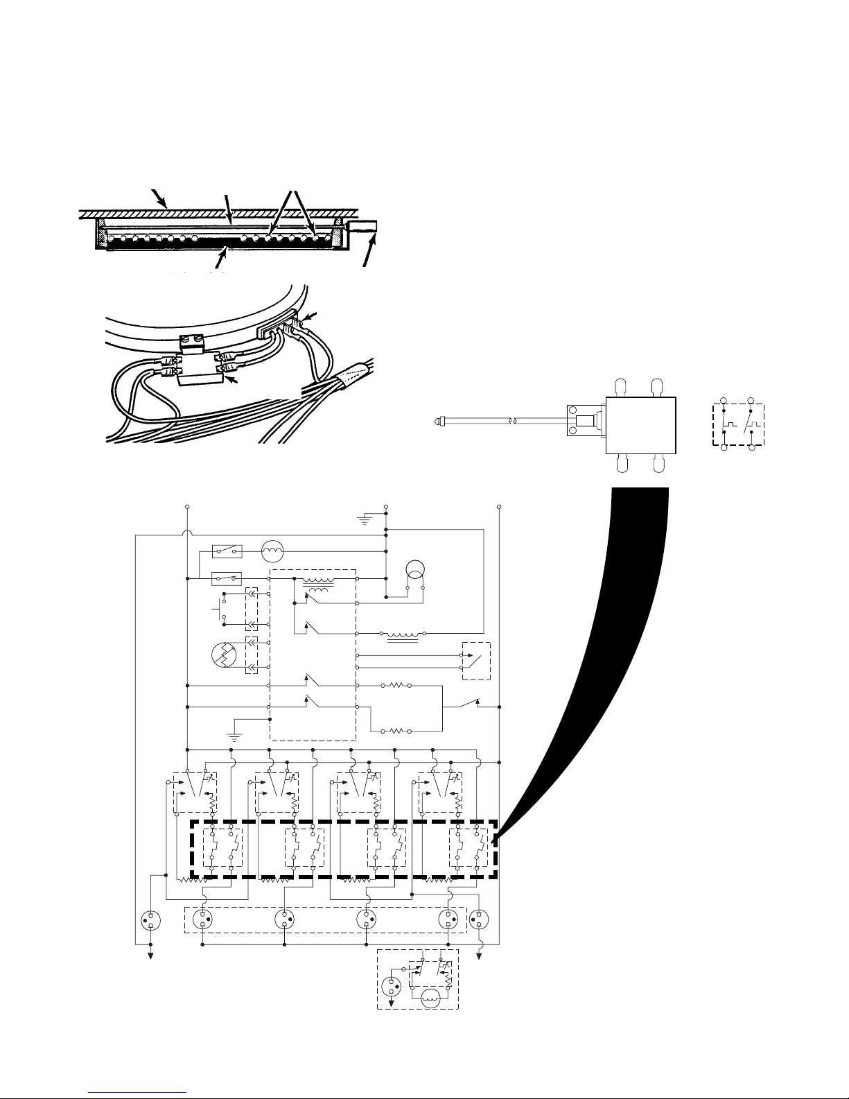
THE SURFACE ELEMENT LIMITER
The surface element limiter is a safety device
that is mounted in the surface element circuit
(see Figure 3-4).
MAINTOP SENSING ROD HEATING COIL
INSULATION LIMITER
ELEMENT
TERMINALS
LIMITER
TERMINALS
Figure 3-4
L1
BK
BI - METAL SW FAN N.O.
YY
BI-METAL SW
AMBIENT N.C.
BK
DOOR
SW.
OVEN
TEMP
SENSOR
W
BK
BK
GND
BK
P
L2L1
LF
M
OVEN CONTROL
P4-3
TRANSFORMER
BK
Y
P3-3
OVEN LIGHT
P3-4
P3-6
P3-7
P2-2
P2-3
OR P6
P3-5
LR
RELAY
LATCH RELAY
BROIL RELAY
BAKE RELAY
L2L1
Y
V
V
G
P
GND
W
W
P4-1
R
P4-4
DOOR LOCK
BR
BU
BU
BROIL ELEMENT
V
R
L2
RF
SOLENOID
BAKE ELEMENT
P4-5
P3-1
P3-2
P2-1
P2-4
L1
P
The limiter monitors the temperature of the
cooktop glass in two ways (see Figure 3-5):
a)Circuit 1A to 2A, which is a normally-
closed (N.C.) switch, opens at 1025˚F
and protects the ceran glass from heat
damage.
b)Circuit 1B to 2B, which is a normally-
open switch (N.O.) switch, closes and
turns on the hot surface indicator lights
if the temperature of the cooktop is
greater than 150˚F. This switch will remain closed until the ceran glass is
warm enough to touch.
2A 2B
1A
Figure 3-5
L2
R
OVEN LT.
W
W
N.O.
COM
BU
P
DOOR
LATCH SW.
R
DLB RELAY
R
L2L1
RR
R
1B
2A 2B
1A
1B
H1 H2
BK
2ABK2B
1A 1B
V
BU
SURF
N
IND.
LIGHT
LF
H1 H2
Y
2AY2B
1A 1B
V
HOT SURFACE
LR
IND. LIGHTS
H1 H2
BR
BU
2ABR2B
1A
V
RF
SUR.
IND.
LIGHT
1B
P
N
3-4
L1
H1
H1 H2
R
BU
RR
H2
2ABU2B
1A
L2
INF.SWITCH
COIL ELEMENT
1B
V
SURF
IND.
LIGHT
N
(OPTIONAL)
Page 19
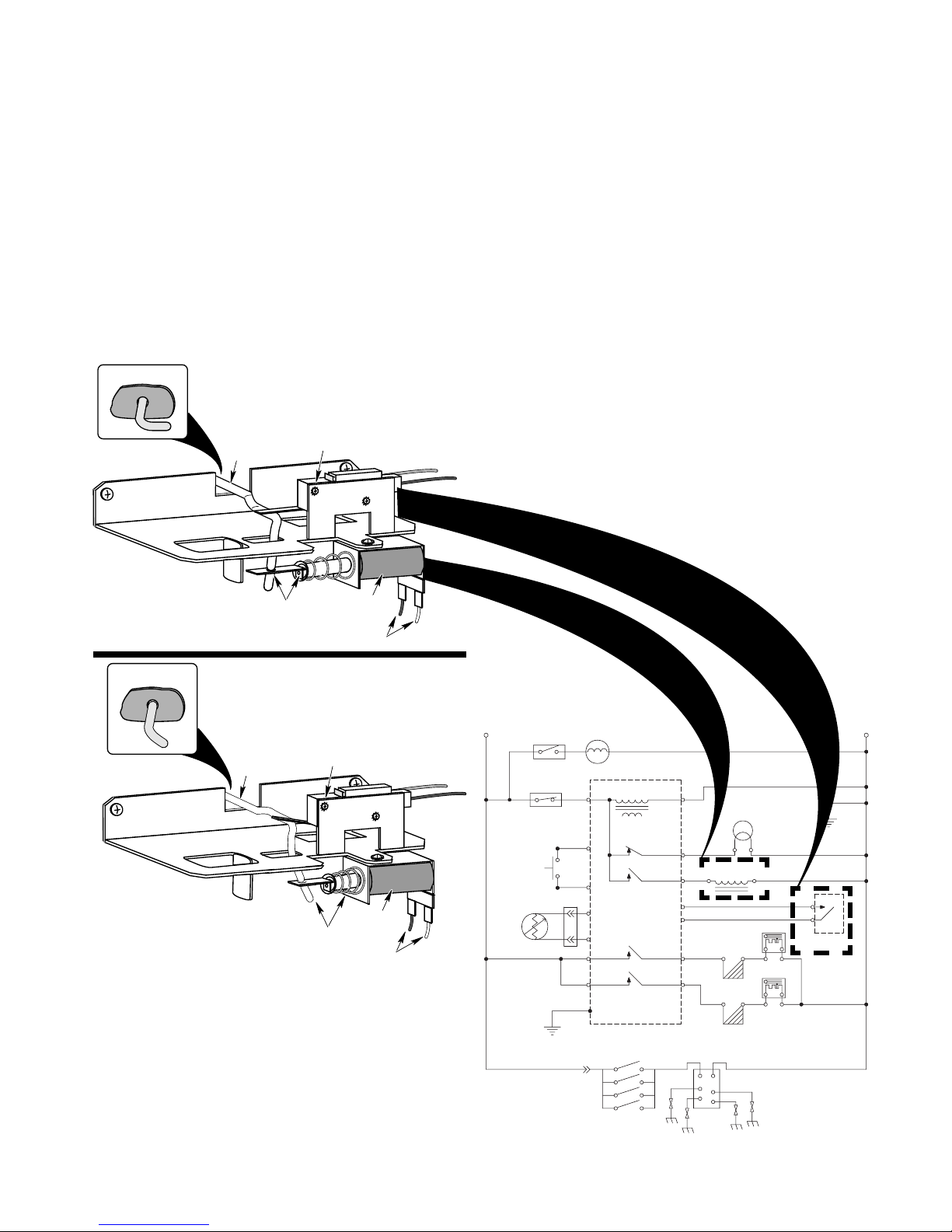
THE DOOR LOCK SOLENOID & DOOR LATCH SWITCH
The door lock solenoid operates on a 120-volt
pulse from the electronic control board. When
the door is in the unlocked position, (Figure
3-6A), the plunger is extended. When the door
latch switch is open, the control senses that
the door is unlocked. When the door latch
switch closes, the control senses that the door
is locked. The door latch switch, mounted on
the solenoid bracket, is in the N.O. (normally-
DOOR
UNLOCKED
Figure 3-6A
LATCH
ACTUATOR
ROD
DOOR LATCH
SWITCH OPEN
The Door Lock Solenoid
(Door Unlocked)
open) position. During the self-clean cycle, the
control board sends a 120-volt pulse to the solenoid windings, which pulls the plunger in, and
moves the latch actuator rod to lock the oven
door (Figure 3-6B). The movement of the rod
also actuates the door latch switch and closes
it. When the self-clean cycle is over, the control board sends a 120-volt pulse to the solenoid, the plunger is pushed out, the latch actuator rod releases the door, and the door latch
switch opens.
DOOR UNLOCKED
DOOR
LOCKED
LATCH
ACTUATOR
ROD
Figure 3-6B
The Door Lock Solenoid
(Door Locked)
PLUNGER OUT
DOOR LATCH
SWITCH CLOSED
PLUNGER IN
DOOR LOCKED
SOLENOID
120 VAC
SOLENOID
120 VAC
L1
BI - METAL SW FANN.O.
YY
BK
BI-METAL SW
AMBIENT N.C.
BK
BK
DOOR
SW.
OVEN
TEMP
SENSOR
BK
GND
G
BK
M
P4-3
BK
Y
P3-3
Y
P3-4
V
P3-6
V
P3-7
P2-2
P2-3/P6
P3-5
OVEN CONTROL
TRANSFORMER
OVEN LIGHT RELAY
LATCH RELAY
BROIL RELAY
BAKE RELAY
SURFACE BURNER
IGNITION SWITCHES
W
P4-1
OVEN LT.
GND
R
P4-4
P4-5
P3-1
P3-2
P2-1
P2-4
DOOR LOCK
BR
BU
BU
V
R
BROIL IGNITOR
BAKE IGNITOR
SPARKMOD ULE
SOLENOID
W
BU
BROIL VALVE
R
BAKE VALVE
N.O.
COM
DOOR
LATCH SW.
N
W
W
W
W
3-5
Page 20
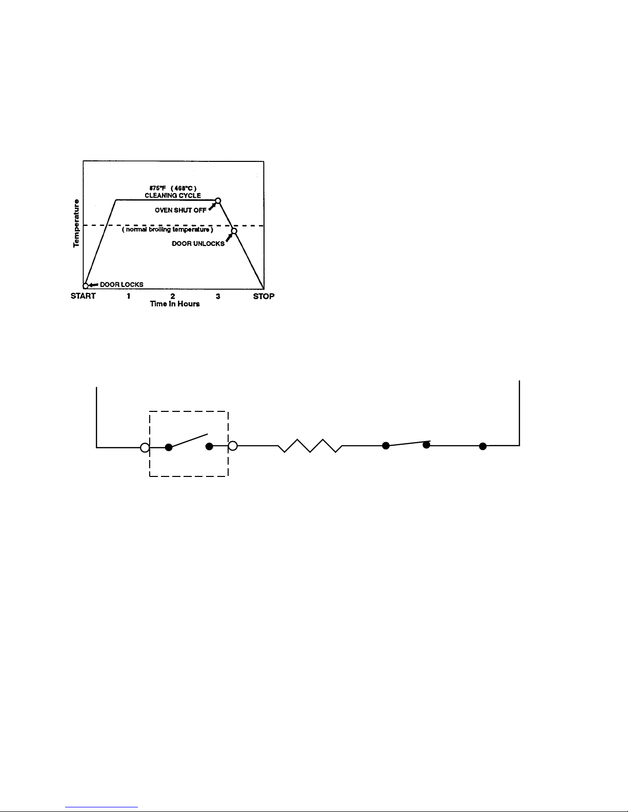
HOW THE SELF-CLEAN CYCLE WORKS
The Self-Clean cycle uses high heat to burn
away soil and grease from inside the oven.
During this cycle, the oven will get much hotter than it does under normal baking and broiling conditions (see the following chart).
AFTER 30-MINUTES OF CLEAN
L1
The oven is preset for a 3-1/2 hour Self-Clean
cycle. However, you can adjust this cycle time
to between 2-1/2 and 4-1/2 hours. The chart
shows a normal 3-1/2 hour Self-Clean cycle.
Note that although the heating turns off after
3-hours, the door will remain locked for an additional 1/2 hour so the oven can cool sufficiently.
During the Self-Clean cycle, the bake element
is on all the time (see Figure 3-7). If the door
latch switch is not activated during the clean
operation, the cycle is terminated and the display will show “close door.”
L2
MICROCOMPUTER
BAKE
ELEMENT
P2-4P2-3
DLB
RELAY
Figure 3-7
3-6
Page 21
COMPONENT ACCESS
COMPONENT LOCATIONS
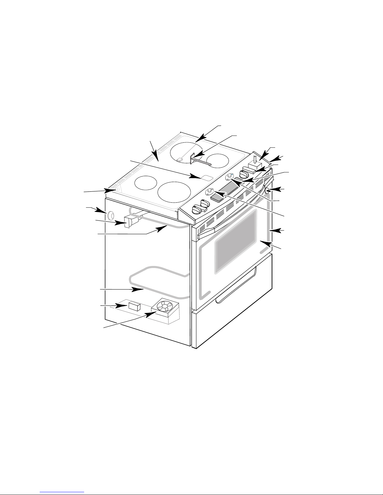
This section instructs you on how to service
each component inside the self-cleaning slidein electric ranges. The components and their
locations are shown in Figure 4-1.
Ceran Glass Maintop
Hot Surface Indicators
Oven Vent
Oven Light
Door Latch Assembly
Broil Element
NOTE: The Whirlpool Model GY396LX range
is shown below. The other slide-in range components are identical, and are serviced in the
same manner.
Surface Element (4)
With Limiter (4)
Oven Temperature Sensor
Element Control (4)
(Infinite Switch)
Control Panel
Surface Indicator Light (2)
Electronic
Oven Control
Oven Light Switch
Cooling Fan
Bimetal Switch
Ambient
Bimetal Switch
Fiberglass Door
Gasket
Oven Door Glass
Bake Element
Double Line
Break (DLB) Relay
Cooling Fan
Figure 4-1
4-1
Page 22
REMOVING THE ELECTRONIC OVEN CONTROL
& THE CONTROL PANEL
4. To remove the electronic oven control:
WARNING
Electrical Shock Hazard
Disconnect from electrical supply before servicing unit.
Failure to do so could result in death or
electrical shock.
CAUTION: When you work on the range, be
careful when handling the sheet metal parts.
Sharp edges may be present, and you can cut
yourself if you are not careful.
1. Turn off the electrical power to the range.
2. Remove the knobs from the controls.
Refer to Figure 4-2 for the following steps.
3. Unsnap the two clips at the inner control
locations and lift the front edge of the
control panel glass, then slide the top
edge of the glass out of the control panel
flange, and remove it.
a) Remove the two screws from the be-
zel and window and remove them from
the control panel.
b) Remove the two screws from the
bracket, lift the electronic oven control
assembly off the control panel, and rotate it back so you can access the connectors.
c) Disconnect the three connectors from
the electronic oven control (see the
inset).
5. To remove the control panel:
a) Remove the two top screws and the
two side screws in the end caps from
the control panel.
b) Open the oven door and remove the
three bottom screws.
c) Remove the control panel from the
range by pulling it forward and lifting it
at the front.
d) To remove an end cap, remove the two
mounting screws (1 top & 1 bottom).
4-2
Page 23
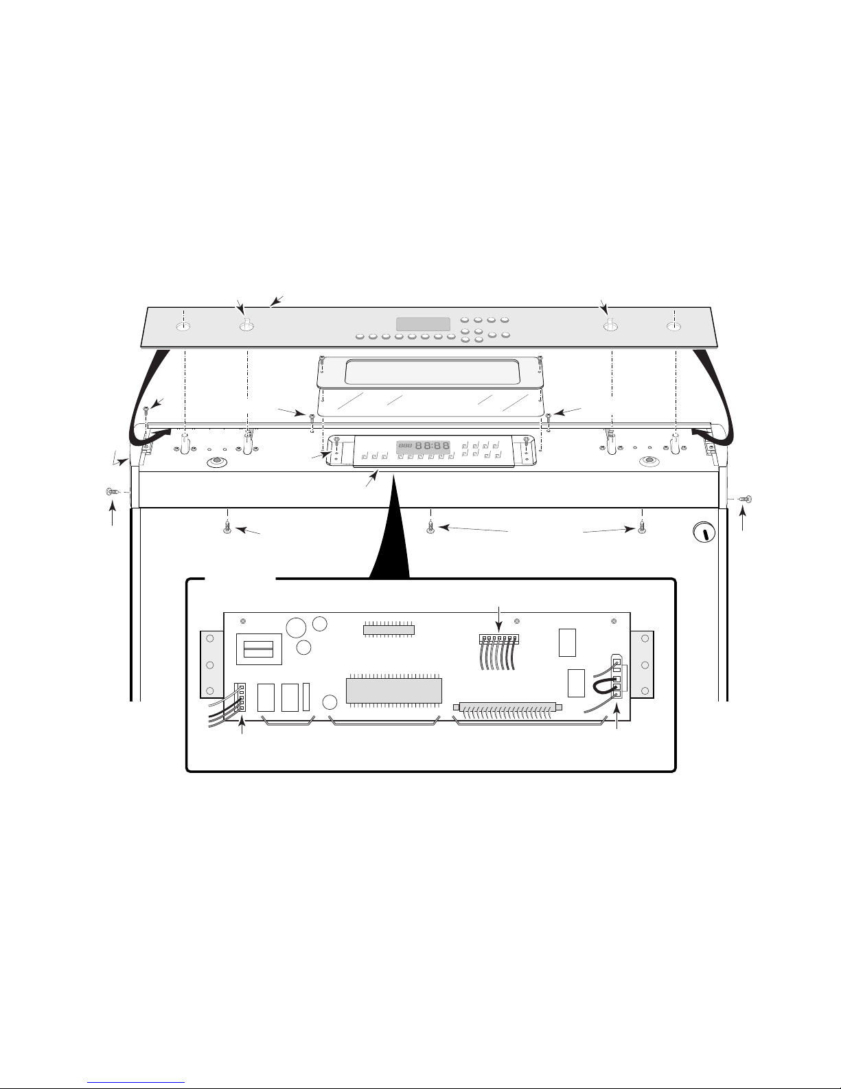
Screw
End
Cap
End
Cap
Bottom Screw
Side
Screw
Side
Screw
Bottom Screws
CONTROL PANEL
Top Screw
Bracket
Top Screw
Control Panel Glass
Unsnap Clip
To Remove Glass
Unsnap Clip
To Remove Glass
Bezel
Window
Electronic Oven Control
5-Pin Connector
PH01
7-Pin Connector
PH03
5-Pin Connector
PT02
ELECTRONIC OVEN CONTROL
(COMPONENT SIDE)
INSET
Figure 4-2
4-3
Page 24
REMOVING AN ELEMENT CONTROL (INFINITE SWITCH)
LENS
SLIDE LIGHT
HOLDER CLIPS
OVER/OFF SHOULDER
CONTROL
PANEL
PRESS UP
TO ENGAGE
CLIPS WITH
LENS SHOULDER
& A SURFACE INDICATOR LIGHT
4. To remove a surface indicator light:
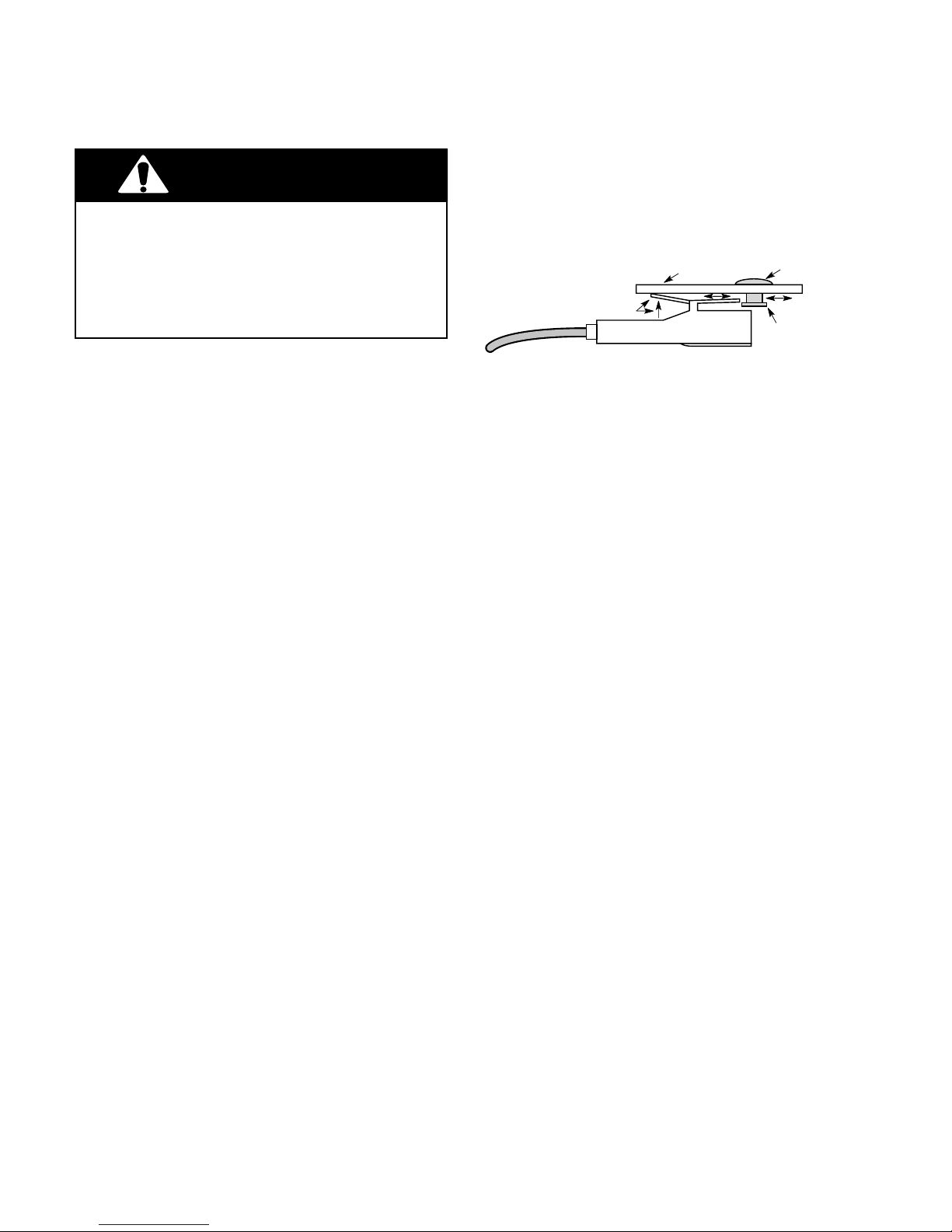
WARNING
Electrical Shock Hazard
Disconnect from electrical supply before servicing unit.
Failure to do so could result in death or
electrical shock.
CAUTION: When you work on the range, be
careful when handling the sheet metal parts.
Sharp edges may be present, and you can cut
yourself if you are not careful.
1. Turn off the electrical power to the range.
2. Remove the control panel (see page 4-2
for the removal procedure). NOTE: You
do not have to remove the electronic oven
control from the panel.
Refer to Figure 4-4 for the following steps.
3. To remove an element control:
a) Remove the two mounting screws from
the element control.
b) Rotate the control panel back on top
of the maintop so you can access the
element control wiring.
c) Disconnect the wires from the termi-
nals on the element control and reconnect them to the identically-marked terminals of the new control (see the inset).
a) Hold the lens in place with one hand
and unclip the indicator light from the
lens (see Figure 4-3).
Figure 4-3
b) Disconnect the one indicator light lead
from the element control terminal, and
cut the other lead near the indicator
light body.
c) Connect the lug on the lead of the new
indicator light to the element control
terminal.
d) Remove 3/8" of insulation from the cut
wire ends and splice them together using a twist-on nut.
4-4
Page 25
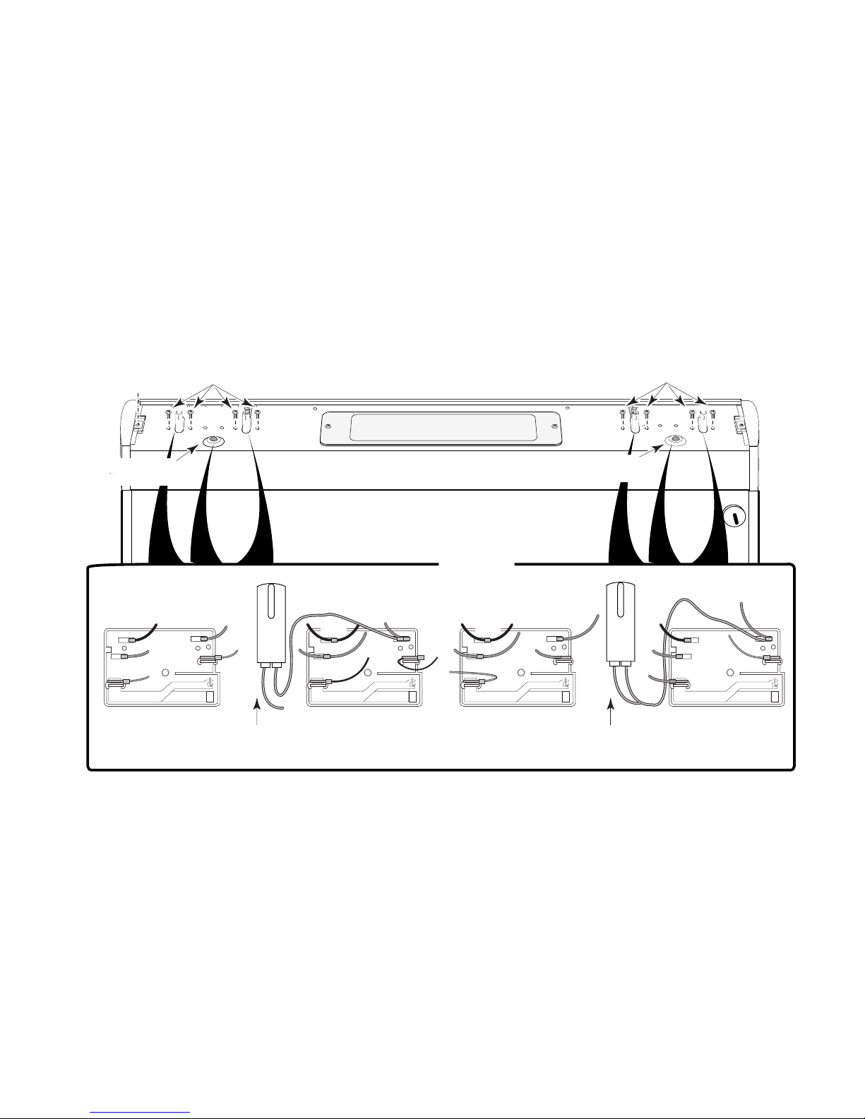
Element
Control
Screws
Element
Control
Screws
Left Surface
Indicator Light
Blk
L1
Red
L2
Ye l
H2
LEFT REAR
Right Surface
CONTROL PANEL
Indicator Light
INSET
2 Red
Blk
2 Red
Blk
Brn
L1
Brn
L2
H2
P
H1
RIGHT FRONT
Red
P
Ye l
H1
Left Surface
2 Blk 2 Blk
L1
2 Red 2 Red
L2
H2
LEFT FRONT
Indicator Light
Figure 4-4
Red
P
H1
Right Surface
Blu
Blk
Red
L1
Red
L2
H2
RIGHT REAR
P
H1
Indicator Light
4-5
Page 26
REMOVING A BIMETAL SWITCH
1. Turn off the electrical power to the range.
WARNING
Electrical Shock Hazard
Disconnect from electrical supply before servicing unit.
Failure to do so could result in death or
electrical shock.
CAUTION: When you work on the range, be
careful when handling the sheet metal parts.
Sharp edges may be present, and you can cut
yourself if you are not careful.
Screw
2. Remove the control panel and rotate it
back on top of the maintop so it is out of the
way (see page 4-2 for the removal procedure). NOTE: You do not have to remove
the electronic oven control from the panel.
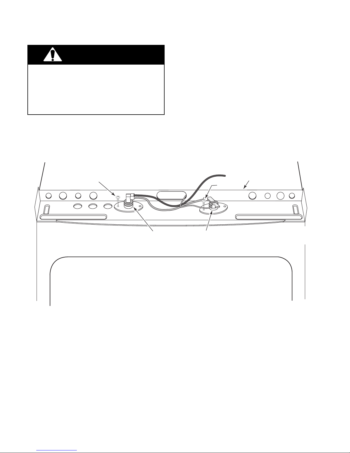
3. To remove a bimetal switch, remove the
mounting screw and disconnect the wires
from the terminals (see Figure 4-5).
Control Panel
Chassis
Screw
Ambient
Bimetal Switch
Figure 4-5
Cooling Fan
Bimetal Switch
4-6
Page 27
REMOVING THE CERAN GLASS MAINTOP
WARNING
Electrical Shock Hazard
Disconnect from electrical supply before servicing unit.
Failure to do so could result in death or
electrical shock.
2. Remove the control panel and rotate it
back on top of the maintop so it is out of the
way (see page 4-2 for the removal procedure). NOTE: You do not have to remove
the electronic oven control from the panel.
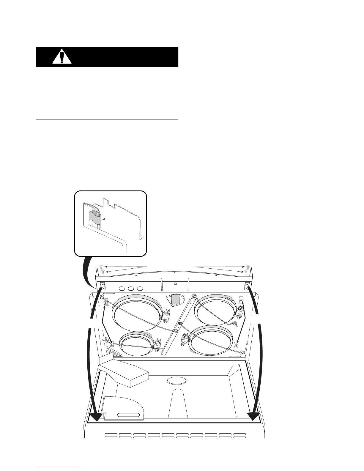
Refer to Figure 4-6 for the following steps.
3. Remove the four chassis screws (two on
each side) from the control panel chassis.
CAUTION: When you work on the range, be
careful when handling the sheet metal parts.
Sharp edges may be present, and you can cut
yourself if you are not careful.
1. Turn off the electrical power to the range.
Fan Motor
Wires In Clip
Control Panel Chassis Screws
4. Lift the front of the chassis at the center
and prop it up with a board. NOTE: You
may have to unclip the two cooling fan
motor wires to raise the chassis high
enough to access the screws.
5. Remove the four mounting screws from
the ceran glass brackets.
6. Lower the chassis and remove the ceran
glass.
CERAN GLASS
MOUNTING SCREWS
4-7
CERAN GLASS
MOUNTING SCREWS
Figure 4-6
Page 28
REMOVING A SURFACE ELEMENT &
HOT SURFACE INDICATOR LIGHT ASSEMBLY
WARNING
Electrical Shock Hazard
Disconnect from electrical supply before servicing unit.
Failure to do so could result in death or
electrical shock.
CAUTION: When you work on the range, be
careful when handling the sheet metal parts.
Sharp edges may be present, and you can cut
yourself if you are not careful.
1. Turn off the electrical power to the range.
4. Lift the front of the chassis at the center
and prop it up with a board. NOTE: You
may have to unclip the two cooling fan
motor wires at the left front corner to raise
the chassis high enough to access the
screws.
5. To remove the left front or right rear
element:
a) Remove the screw from the retaining
rod.
b) Disconnect the wires from the termi-
nals of the element and limiter.
6. To remove the left rear or right front
elements,
2. Remove the control panel and rotate it
back on top of the maintop so it is out of the
way (see page 4-2 for the removal procedure). NOTE: You do not have to remove
the electronic oven control from the panel.
Refer to Figure 4-7 for the following steps.
3. Remove the four chassis screws (two on
each side) from the control panel chassis.
a) Pull the ends of the rod out from the
brackets.
b) Disconnect the wires from the termi-
nals of the element and limiter.
7. To remove the hot surface indicator
light assembly:
a) Pull down firmly on the indicator as-
sembly body to unfasten the four clips
from the edge of the chassis.
b) Disconnect the leads from the termi-
nals of the limiters.
4-8
Page 29
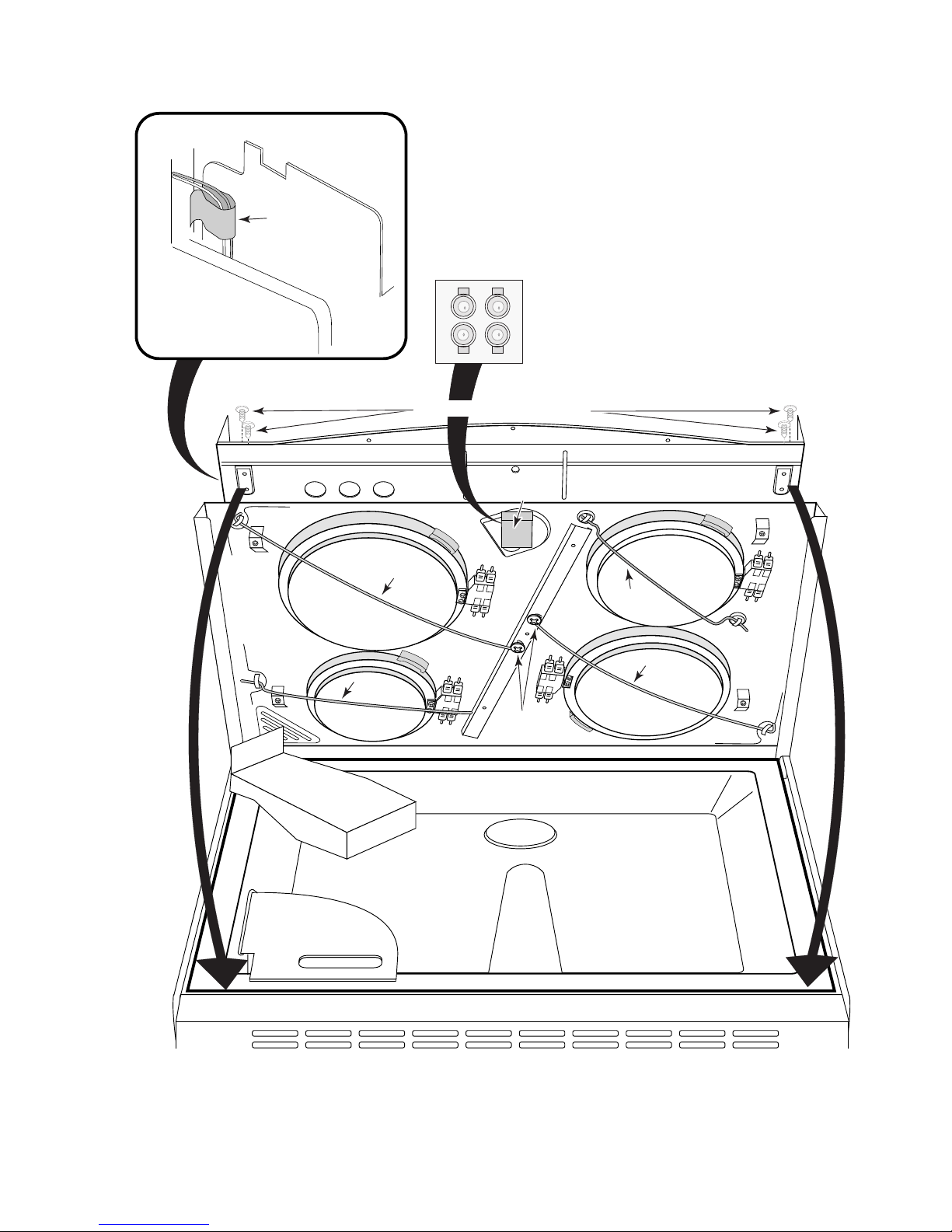
Fan Motor
Wires In Clip
TOP VIEW
Control Panel Chassis Screws
Hot Surface
Indicator Lights
Left Front
9" 2400 W
Retaining
Rod
Left Rear
6" 1400 W
Retaining
Rod
Limiter
Limiter
Mounting
Screws
Limiter
Retaining
Rod
Retaining
Rod
Right Rear
8" 2100 W
Right Front
7" 1700 W
Limiter
Figure 4-7
4-9
Page 30
REMOVING THE OVEN BAKE & BROIL ELEMENTS
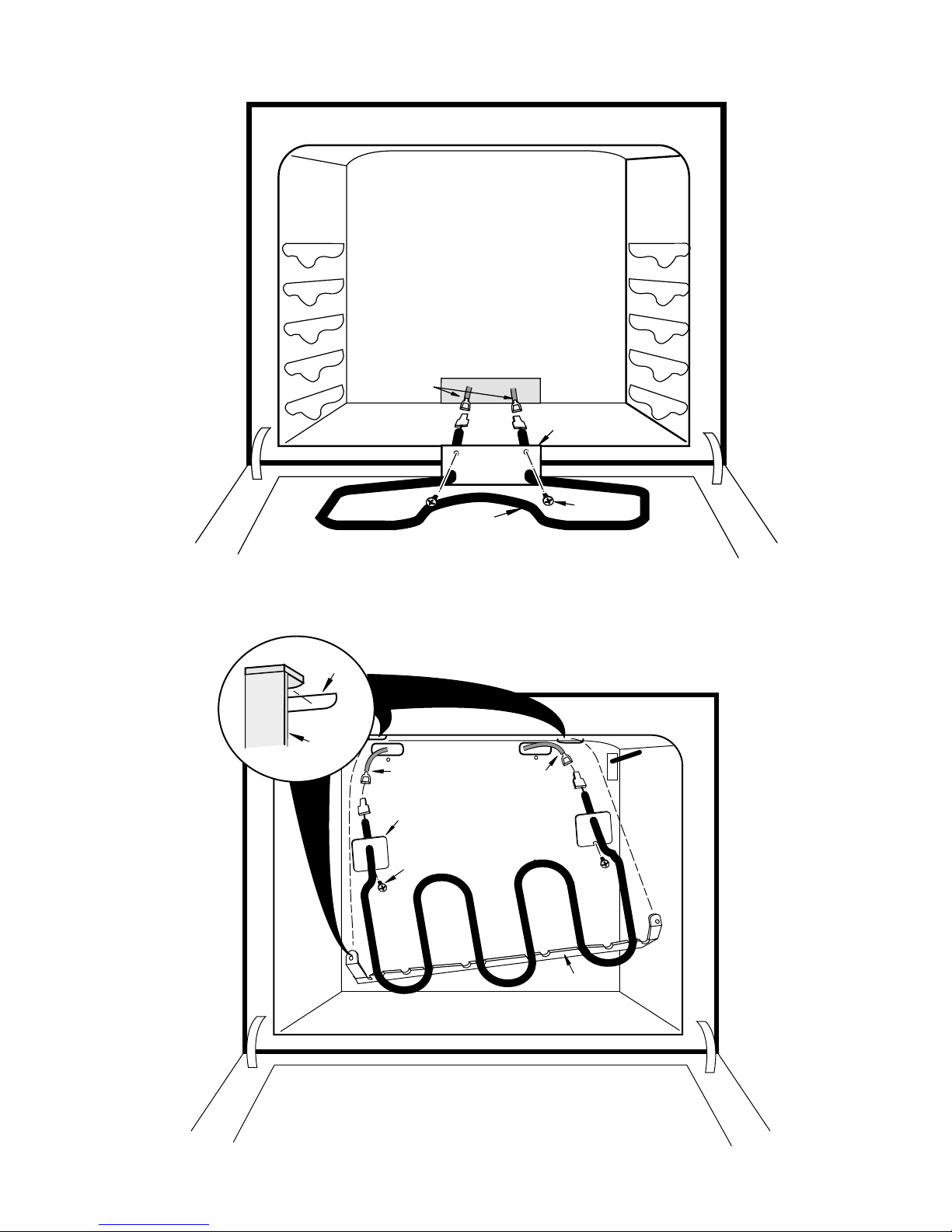
Refer to Figure 4-8 for the following steps.
WARNING
Electrical Shock Hazard
Disconnect from electrical supply before servicing unit.
Failure to do so could result in death or
electrical shock.
CAUTION: When you work on the range, be
careful when handling the sheet metal parts.
Sharp edges may be present, and you can cut
yourself if you are not careful.
1. Turn off the electrical power to the range.
2. To remove the bake element:
a) Remove the two screws from the
mounting plate and pull the element
forward as far as the wires will allow.
b) Disconnect the wires from the bake el-
ement terminals and remove the element.
Refer to Figure 4-9 for the following steps.
3. To remove the broil element:
a) Remove the two screws from the broil
element mounting plates.
b) Pull the broil element forward and un-
hook the bracket tabs from the slots.
c) Pull the broil element forward as far as
the wires will allow, disconnect the
wires from the broil element terminals,
and remove the element.
4-10
Page 31
Red Wires
Mounting
Plate
Slot
Bracket
Figure 4-8
Blue Wire
Mounting Plate
Screw
BAKE
ELEMENT
BROIL
ELEMENT
Screw (2)
Blue Wire
Bracket
Figure 4-9
4-11
Page 32
REMOVING THE OVEN LIGHT ASSEMBLY
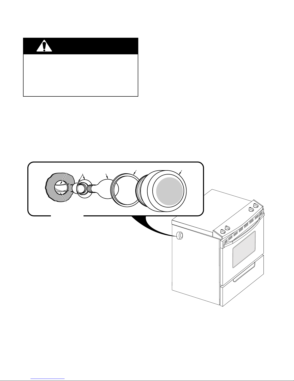
Refer to Figure 4-10 for the following steps.
WARNING
Electrical Shock Hazard
Disconnect from electrical supply before servicing unit.
Failure to do so could result in death or
electrical shock.
CAUTION: When you work on the range, be
careful when handling the sheet metal parts.
Sharp edges may be present, and you can cut
yourself if you are not careful.
1. Turn off the electrical power to the range.
2. Open the oven door and remove the oven
racks.
GRAY WIRE
SOCKET/
SHIELD
LIGHT
BULB
GASKET
3. Unscrew the oven light lens and remove
the lens and the gasket.
4. Unscrew the light bulb and set it aside.
5. Use a screwdriver blade and pry the old
light socket assembly out of the oven
opening and pull it forward as far as the
wiring will allow.
6. Remove the wires from the light socket
terminals.
7. Connect the wires to the new light socket
terminals and then press the socket assembly into the opening until it snaps into
place.
LENS
WHT WIRES
INSET
Figure 4-10
4-12
Page 33
REMOVING THE OVEN DOOR GASKET
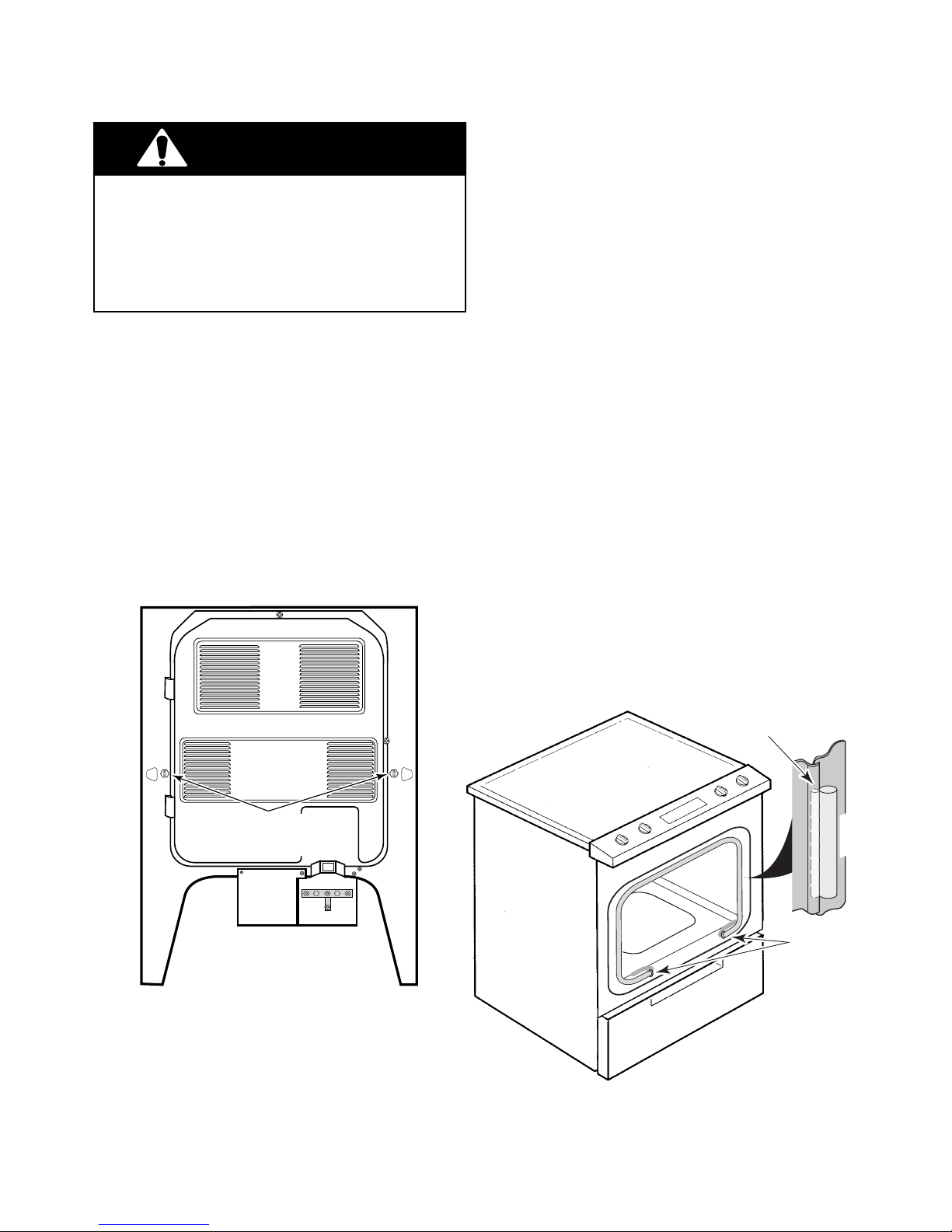
Refer to Figure 4-12 for the following steps.
WARNING
Electrical Shock Hazard
Disconnect from electrical supply before servicing unit.
Failure to do so could result in death or
electrical shock.
CAUTION: When you work on the range, be
careful when handling the sheet metal parts.
Sharp edges may be present, and you can cut
yourself if you are not careful.
1. Turn off the electrical power to the range.
2. Pull the range out from the cabinet far
enough to access the back panel.
3. Loosen (do not remove) the two gasket
retaining screws (see Figure 4-11) so they
extend approximately 1" from the rear
panel.
4. Pull the oven liner forward as far as possible so that the gap in the track for the
door gasket is open.
5. Pull the old door gasket out of the track
and remove the ends from the two holes in
the front.
NOTE: The door gasket is divided into two
segments along its length. The smaller segment has a piece of rope inside it, and the
larger segment is hollow. Install the smaller
segment with the rope into the track in the next
step.
6. Use a screwdriver blade and insert 5
"
at
one end of the new gasket into either hole
in the front of the oven. Work the smaller
segment of the gasket into the track around
the three sides of the door. When you are
finished, insert the remaining gasket into
the front hole. Make sure that the gasket is
evenly installed all the way around the
door, otherwise a poor seal could result.
Gasket Retaining
Hex-Head Screws
(Loosen—Do Not Remove)
Figure 4-11
7. Tighten the two hex-head screws at the
rear of the range to secure the gasket.
Position Small Rope Section Of
Gasket Under Lip Of Oven Liner
& Large Section Against Frame
Frame
Oven Liner
Press Ends Of
Gasket Into
Holes Of Frame
& Fold Back
Figure 4-12
4-13
Page 34
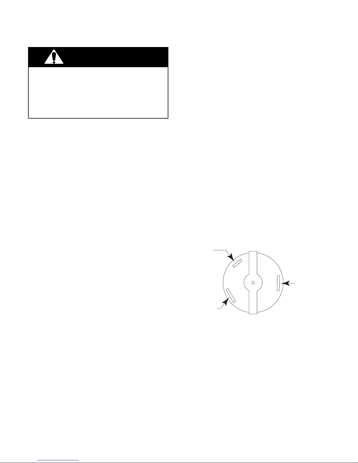
REMOVING THE OVEN LIGHT SWITCH
Yellow
(Narrow Terminal)
Red
(Wide Terminal)
Black
(Wide Terminal)
Refer to Figure 4-14 for the following steps.
WARNING
Electrical Shock Hazard
Disconnect from electrical supply before servicing unit.
Failure to do so could result in death or
electrical shock.
CAUTION: When you work on the range, be
careful when handling the sheet metal parts.
Sharp edges may be present, and you can cut
yourself if you are not careful.
1. Turn off the electrical power to the range.
2. Pull the range out from the cabinet far
enough to access the back panel.
3. Remove the right side panel as follows
(see inset #1). NOTE: The inset shows
installation of the left side panel, however,
the right side panel mounts to the range in
the same manner:
a) Remove the two screws from the rear
panel mounting tabs for the right side
panel.
b) From the back, push the side panel for-
ward as far as it will go and unhook it
from the screw at the top front corner.
c) Pull the top away from the range sev-
eral inches, then lift the panel free of
the retaining clips at the bottom.
4. Press in on the locking arms while you
push out on the body of the oven light
switch, and remove the switch (see inset
#2).
5. Unplug the three wires from the terminals
of the oven light switch. The wire locators
are shown in Figure 4-13.
Figure 4-13
4-14
Page 35
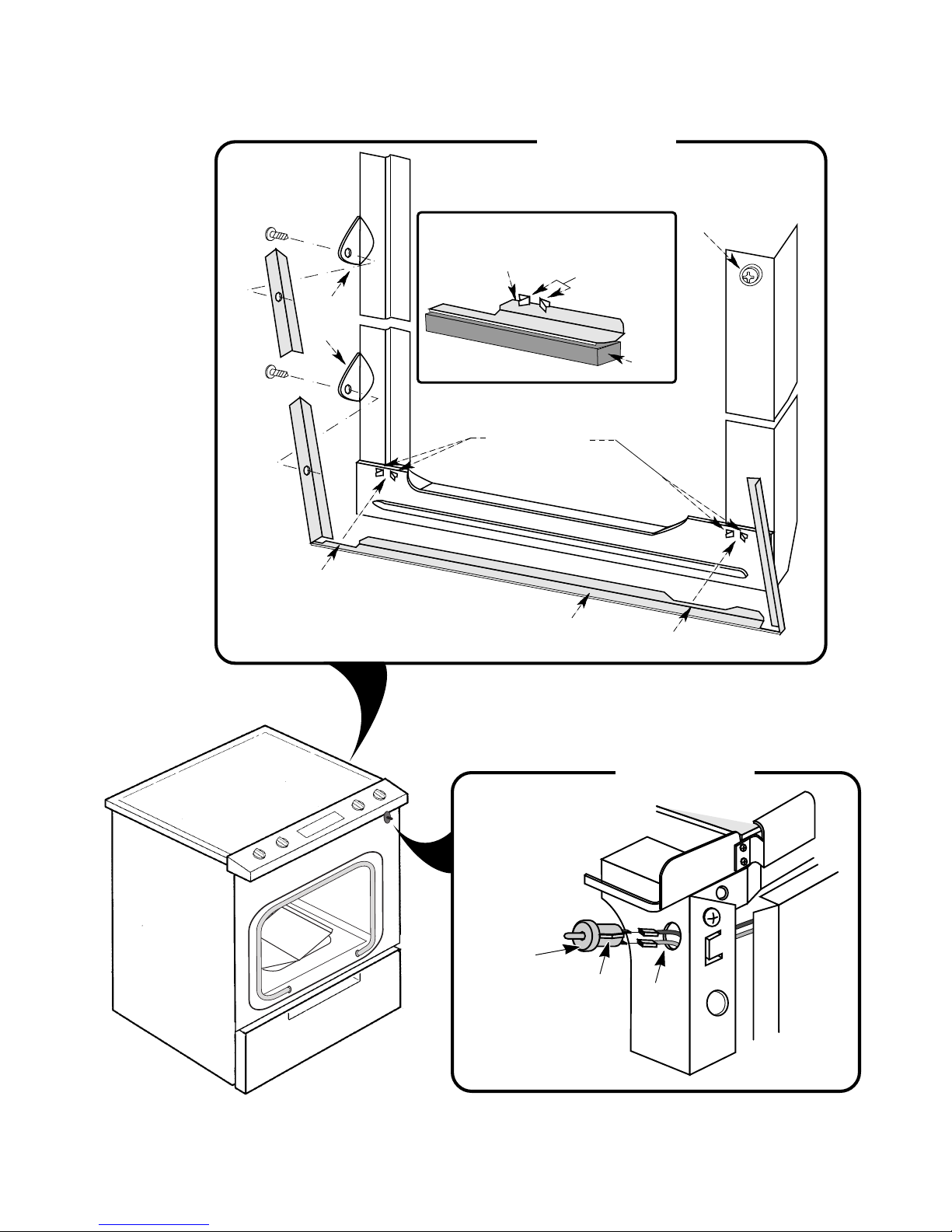
INSET #1
Top Screw
Bottom
Screw
Rear
Panel
Tabs
Cutout
Retaining Clips
Over Top Edge
Of Panel
Retaining Clips
Top Front
Corner Screw
Retaining Clps
RAIL
Side Panel
Cutout
Figure 4-14
INSET #2
Oven Light
Switch
Locking Arm
4-15
Wires
Page 36
REMOVING THE COOLING FAN
Refer to Figure 4-15 for the following steps.
WARNING
Electrical Shock Hazard
Disconnect from electrical supply before servicing unit.
Failure to do so could result in death or
electrical shock.
CAUTION: When you work on the range, be
careful when handling the sheet metal parts.
Sharp edges may be present, and you can cut
yourself if you are not careful.
1. Turn off the electrical power to the range.
2. Pull the range out from the cabinet far
enough to access the back panel.
3. Remove the left side panel from the range
(see step 3 on page 4-14 for the procedure).
4. Remove the storage drawer from the range
and set it aside.
5. From inside the storage drawer area, remove the screw from the front of the housing.
6. From outside the range, remove the remaining screw from the front of the housing, and lower the housing so you can
access the cooling fan mounting screws.
7. Unplug the wires from the terminals of the
cooling fan.
8. Remove the three flat-head screws from
the cooling fan and remove the fan from
the housing.
4-16
Page 37
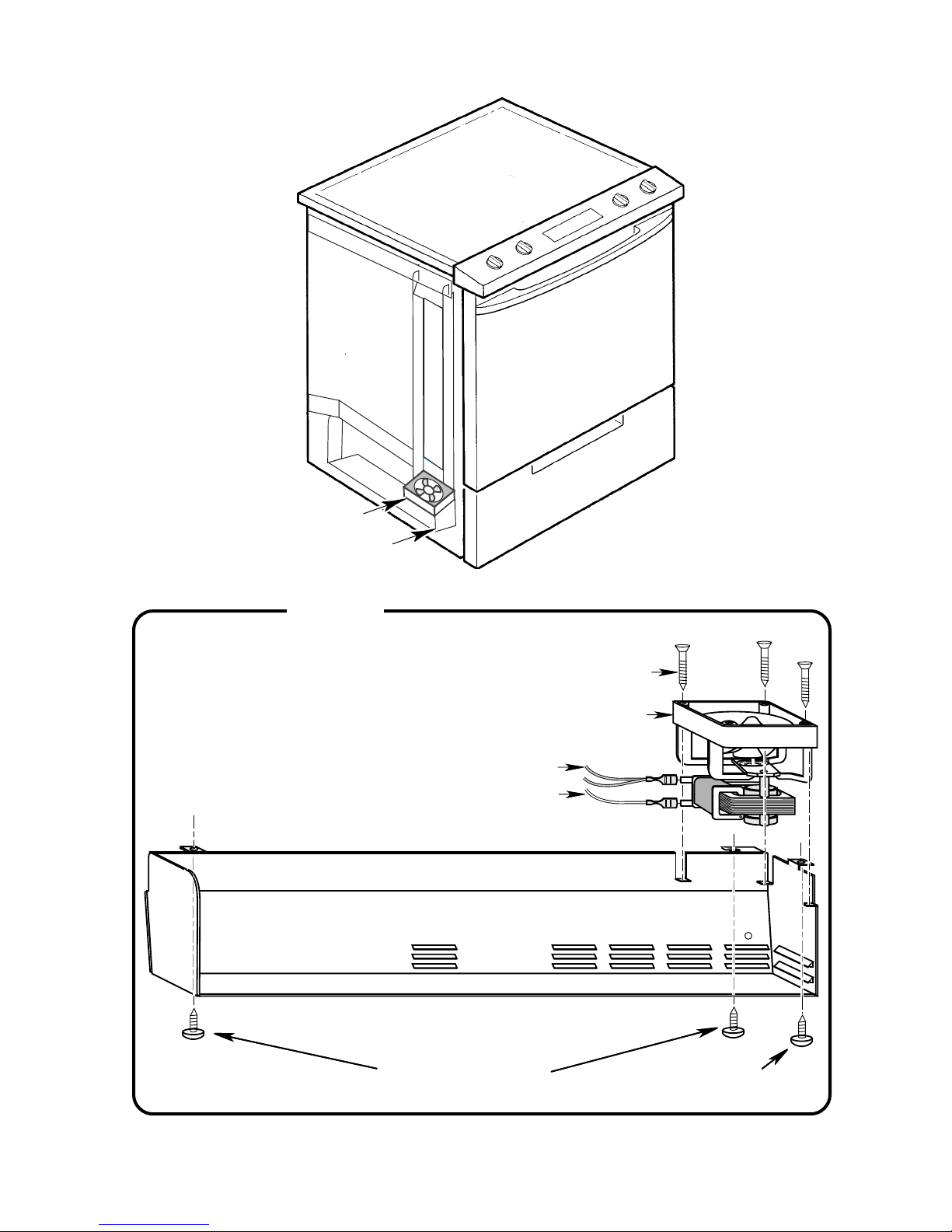
Cooling Fan
Housing
INSET
Figure 4-15
Flat-Head
Screw (3)
Cooling Fan
White Wires
Yellow Wire
HOUSING
Access These Screws
From Inside Storage Drawer Area
4-17
Housing Screw
Page 38
REMOVING THE OVEN TEMPERATURE SENSOR &
THE DOOR LATCH ASSEMBLY COMPONENTS
Refer to Figure 4-17 for the following steps.
WARNING
Electrical Shock Hazard
Disconnect from electrical supply before servicing unit.
Failure to do so could result in death or
electrical shock.
CAUTION: When you work on the range, be
careful when handling the sheet metal parts.
Sharp edges may be present, and you can cut
yourself if you are not careful.
1. Turn off the electrical power to the range.
2. Pull the range out from the cabinet far
enough to access the back panel.
3. Remove the top and side screws from the
component cover on the rear panel and
loosen the bottom screw, then remove the
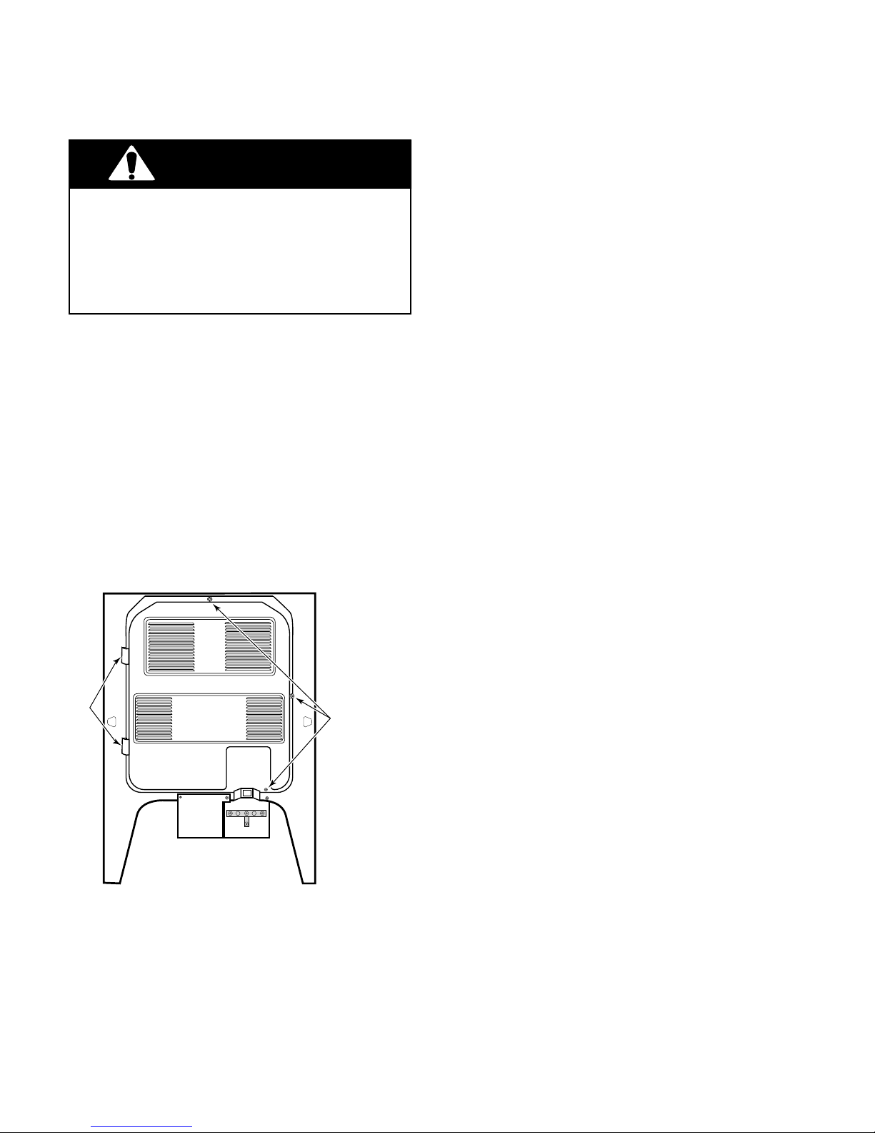
cover (see Figure 4-16).
Top
4. To remove the oven temperature sen-
sor (Inset #1):
a) From inside the oven, remove the
mounting screw and pull the sensor
forward as far as the wires allow.
b) From behind the range, unplug the
connectors from the sensor harness
and the main harness, and push the
wires and connector through the access hole.
5. To remove the door latch switch from
the door latch assembly (Inset #2):
a) Remove the 2-wire connector from the
door latch switch terminals.
b) Remove the two screws and hex nuts
with lockwashers from the body of the
door latch switch and remove the
switch from the bracket.
6. To remove the solenoid from the door
latch assembly (Inset #2):
Tabs
COMPONENT
COVER
Bottom
Figure 4-16
Side
Remove Top &
Side Screws
Loosen Bottom Screw
a) Remove the screw and star washer
from the solenoid, then unhook and
remove it from the bracket. NOTE: The
plunger and spring are separate from
the solenoid. Remove them from the
old solenoid, and install them on the
new one.
b) Disconnect the wires from the termi-
nals of the solenoid.
4-18
Page 39
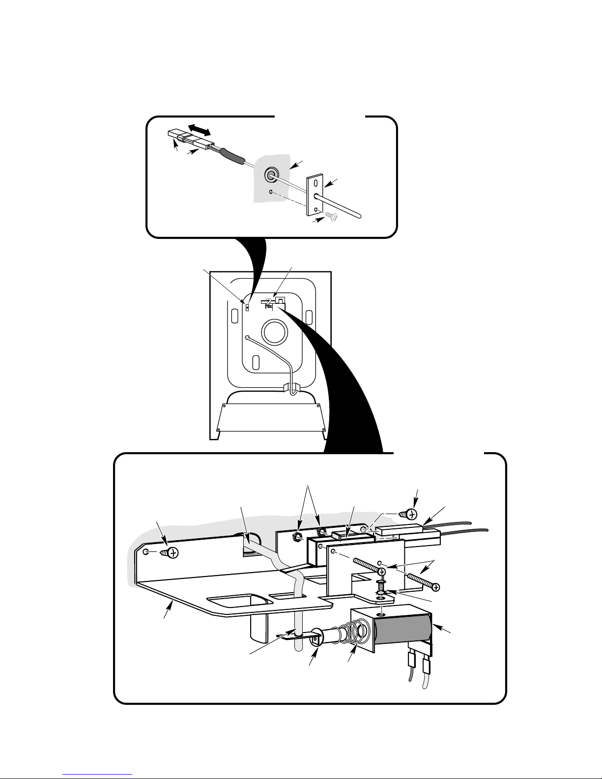
INSET #1
Connectors
TEMPERATURE
OVEN
SENSOR
Mounting
Screw
DOOR LOCK
SOLENOID
Back of Liner
Oven Temperature
Sensor
Figure 4-17
Assembly Mounting
Screw
Bracket
Latch
Actuator Rod
Insert End Of
Rod Into Arm
On Plunger
INSET #2
Hex-Nuts
W/Lockwashers
Plunger
Assembly Mounting
Latch Sensing
Switch
Spring
Brown Wire
Screw
2-Wire Connector
Switch Screws
Solenoid Screw
W/ Star Washer
Solenoid
Yellow Wire
4-19
Page 40
REMOVING THE OVEN DOOR GLASS
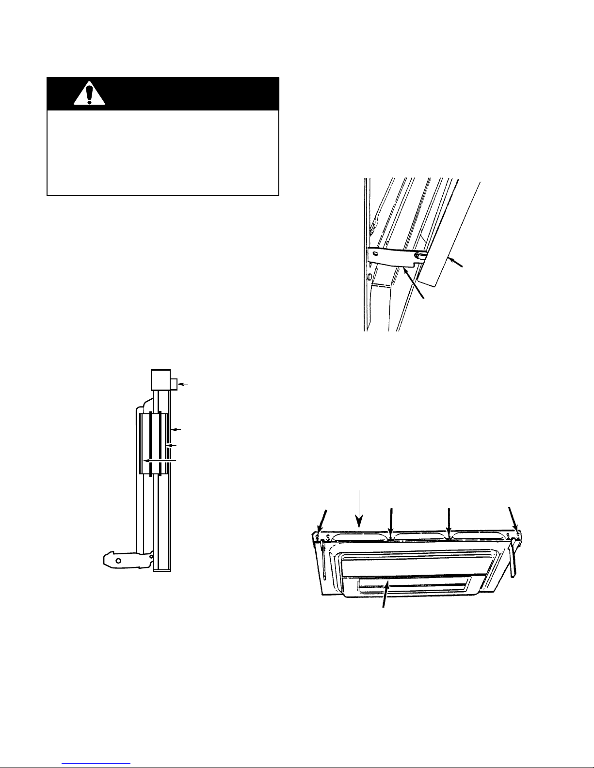
Refer to Figure 4-19 for the following steps.
WARNING
Electrical Shock Hazard
Disconnect from electrical supply before servicing unit.
Failure to do so could result in death or
electrical shock.
CAUTION: When you work on the range, be
careful when handling the sheet metal parts.
Sharp edges may be present, and you can cut
yourself if you are not careful.
NOTE: The oven door has three glass panels
(see Figure 4-18). To replace the oven glass
panels inside the door, you must first remove
the door glass. To replace the inner oven glass,
you have to first remove the door glass and the
outer oven glass panels. Refer to the section(s),
as necessary.
Door Handle
Assembly
1. Open the oven door to the first (broil) stop.
2. Grasp the oven door on both sides. Simultaneously lift straight up and pull out on the
door approximately 2-inches to release
the hinge brackets from their stop.
OVEN DOOR
DOOR HINGE
Figure 4-19
3. Close the door completely so it is perpendicular to the floor, then pull the door out of
the oven tracks, and place it on a clean
padded surface.
Door Glass
Outer Oven Glass
Inner Oven Glass
Figure 4-18
4. Position the door upside down so that it
rests on the top of the handle assembly,
(see Figure 4-20), and remove the four
screws from the door glass retainer.
DOOR GLASS RETAINER
SCREW SCREW SCREW SCREW
DOOR
Figure 4-20
4-20
Page 41
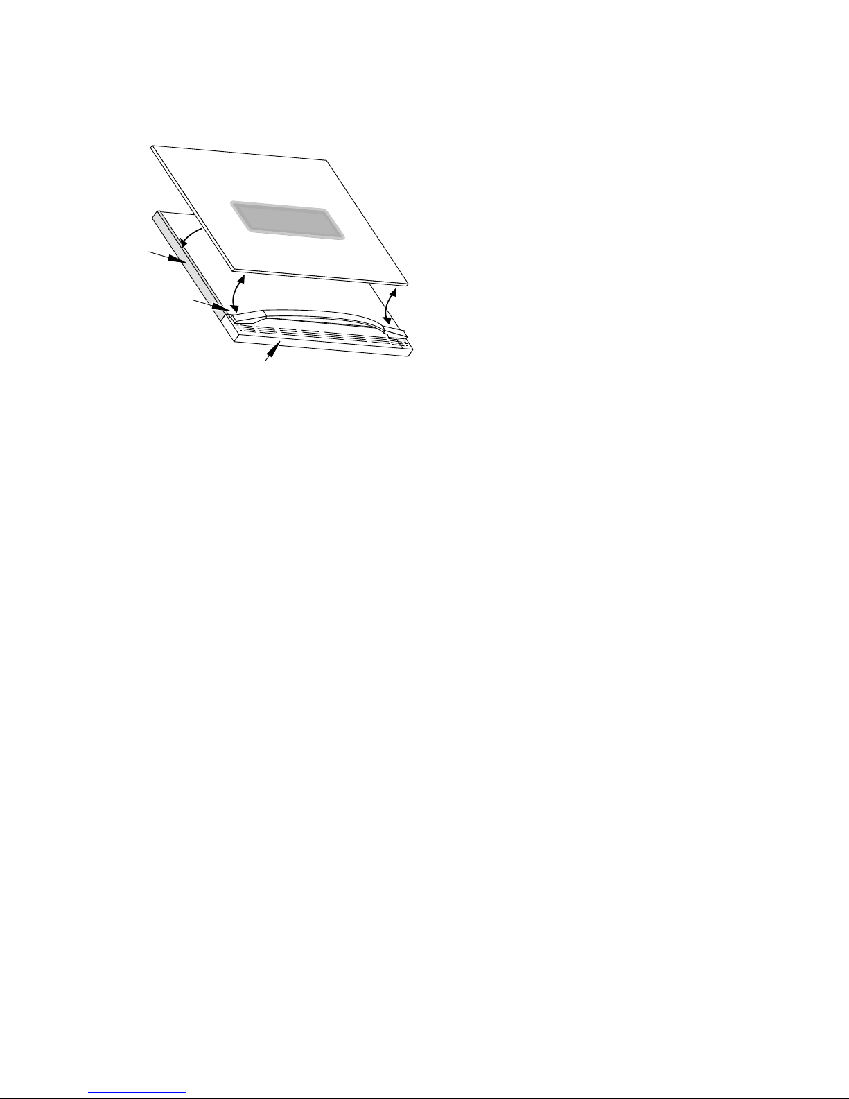
5. Lift the bottom of the door glass and slide
the top out from under the two tabs in the
door handle assembly (see Figure 4-21).
6. Install the new door glass and the retainer.
NOTE: Make sure that the glass is over
the front edges of the side covers and not
under them.
Side Cover
Tab In Handle
Assembly
DOOR GLASS
Door Handle Assembly
Figure 4-21
7. Reinstall the oven door on the range as
follows:
a) Grasp the door by the sides, and slide
the two door hinges into the tracks in
the range slots as far as the stop.
b) Pull the oven door open to the first
(broil) stop.
c) Lift the door straight up, and push in
until the hinges are over the stop and
are fully in place.
d) Close the oven door.
4-21
Page 42
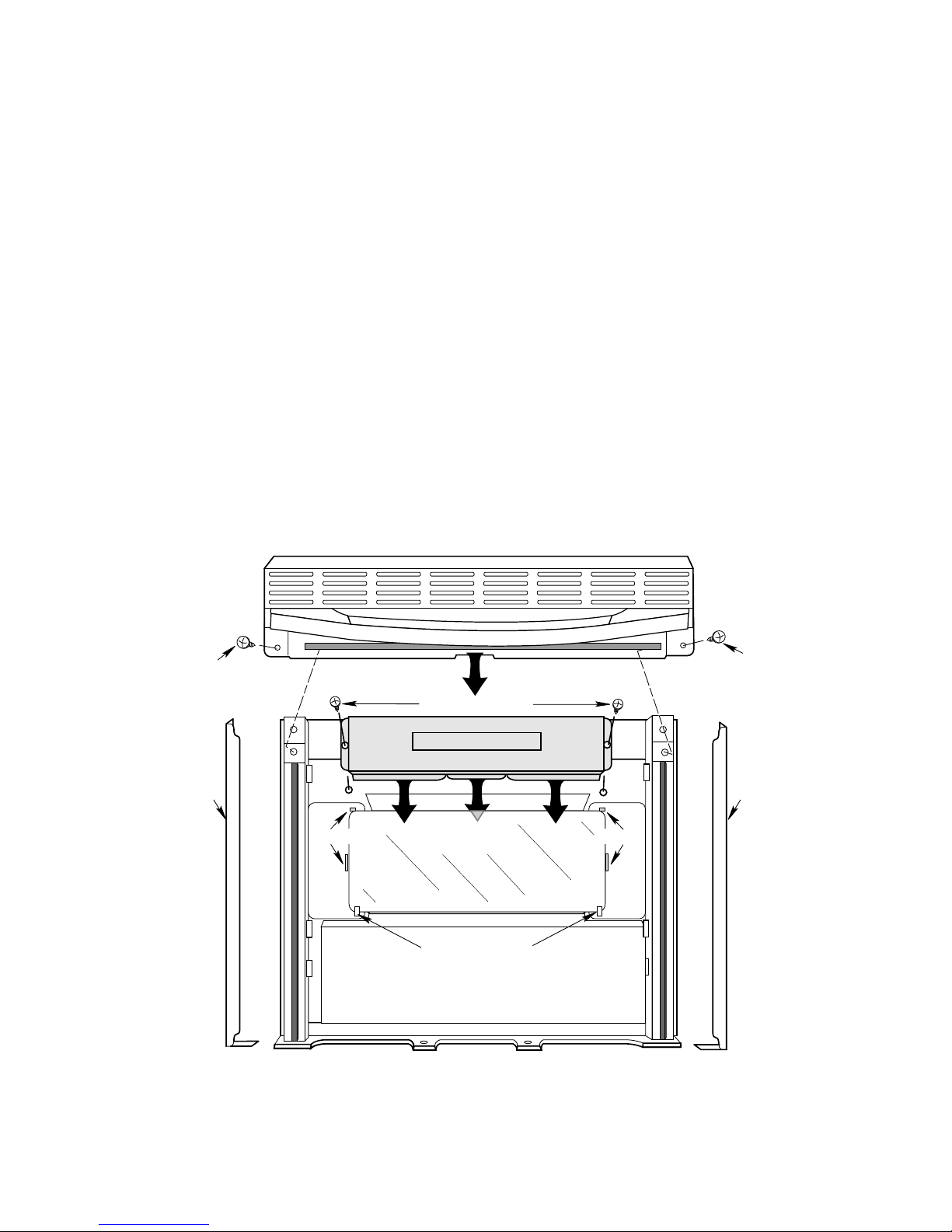
REMOVING THE OUTER OVEN GLASS
1. Refer to “Removing The Oven Door Glass”
on page 4-20 and remove the door glass,
then proceed with the following steps.
Refer to Figure 4-22 for the following steps.
2. Position the oven door as shown in the
illustration.
3. Remove the two screws from the door
handle assembly and remove the assembly.
4. Remove the two side covers.
5. Remove the two screws from the retaining
panel, then unhook the panel from the
outer oven glass and remove it.
6. Unhook the glass from the door tabs and
Door Handle Assembly
remove it.
7. Install the new outer oven glass in the
door.
8. Reassemble the oven door.
9. Reinstall the oven door on the range as
follows:
a) Grasp the door by the sides, and slide
the two door hinges into the tracks in
the range slots as far as the stop.
b) Pull the oven door open to the first
(broil) stop.
c) Lift the door straight up, and push in
until the hinges are over the stop and
are fully in place.
d) Close the oven door.
Handle
Screw
Side
Cover
Panel Screws
RETAINING PANEL
Guides Guides
OUTER OVEN GLASS
Slide Glass Into
These Two Tabs
OUTER DOOR FRAME
Figure 4-22
Handle
Screw
Side
Cover
4-22
Page 43
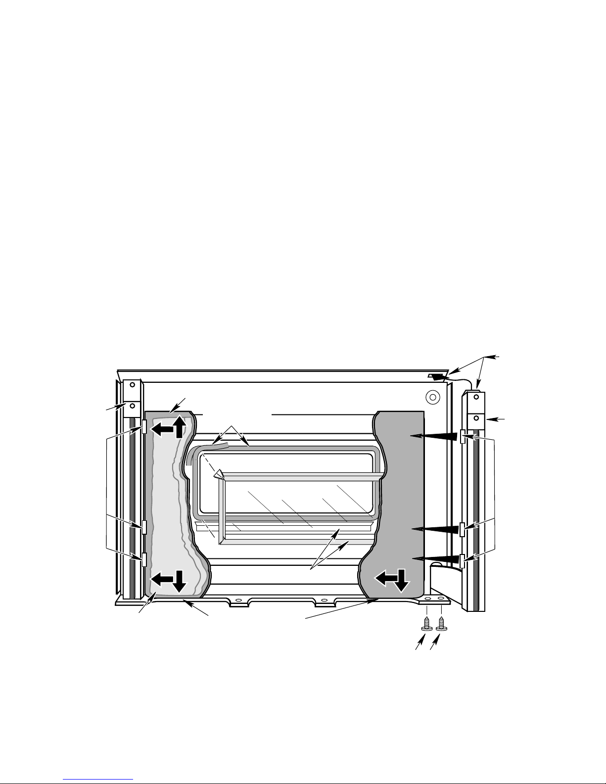
REMOVING THE INNER OVEN GLASS
1. Remove the door glass and the outer oven
glass, as instructed on pages 4-20 through
4-22, then proceed with the following steps.
Refer to Figure 4-23 for the following steps.
2. Position the oven door with the inner oven
glass facing up.
3. Remove the two bottom screws from the
right hinge, then lift the bottom of the hinge
assembly and unhook the top tab from the
slot in the panel, and remove the hinge.
4. Lift the right side of the inner door panel.
Slide the panel out from under the lip at the
bottom of the door, and from under the
three tabs on the left hinge assembly, and
remove the panel.
5. Remove the door insulation blanket.
6. Lift the inner oven glass and frame assembly off the door.
7. If you are replacing the fiberglass gasket
from around the window opening in the
door, remove and replace it at this time.
8. Install the new inner oven glass over the
fiberglass gasket.
9. Reassemble the oven door.
10. Reinstall the oven door on the range as
follows:
a) Grasp the door by the sides, and slide
the two door hinges into the tracks in
the range slots as far as the stop.
b) Pull the oven door open to the first
(broil) stop.
c) Lift the door straight up, and push in
until the hinges are over the stop and
are fully in place.
d) Close the oven door.
Insert Tab
Through Slot
Left Hinge
Assembly
Tabs
Insulation
Blanket
Inner Door Panel
Fiberglass
Gasket
Inner Oven Glass & Frame
Slide Inner Door Panel
Under Lip In Outer Door Frame
Figure 4-23
OUTER DOOR FRAME
Right Hinge
Assembly
Tabs
Hinge Screws
4-23
Page 44

— NOTES —
4-24
Page 45
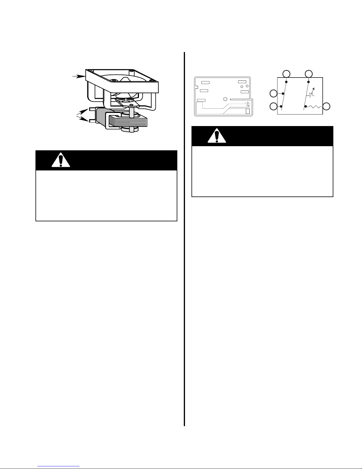
COMPONENT TESTING
WARNING
L1
L2
P
H2
H1
L1
P
H1 H2
L2
COOLING FAN MOTOR
COOLING
FAN MOTOR
TERMINALS
NOTES:
1. FAN RATING IS 120 VAC, 60 HZ, 2.5-WATTS.
WARNING
Electrical Shock Hazard
Disconnect from electrical supply before servicing unit.
Failure to do so could result in electrical
shock or other personal injury.
Test Procedure
Refer to page 4-16 for the location of the
cooling fan motor and the procedure for servicing it.
To test the cooling fan motor windings, perform the following steps:
1. Use an ohmmeter and set the range switch
to R x 1.
2. With no power applied, touch the leads of
the ohmmeter to the terminals of the fan
motor (you do not have to remove the wires
from the terminals). You should obtain a
reading of between 55 Ω and 80 Ω.
If the reading is not within the range shown,
the motor is defective and should be replaced.
ELEMENT CONTROL
(INFINITE SWITCH)
Electrical Shock Hazard
Disconnect from electrical supply before servicing unit.
Failure to do so could result in electrical
shock or other personal injury.
Test Procedure
Refer to page 4-4 for the location of the element controls and the procedure for servicing
them.
To test a control, perform the following steps:
1. Use an ohmmeter and set the range switch
to R x 1.
2. With no power applied, touch the leads of
the ohmmeter to the indicated terminals of
the element control (infinite switch). You
should obtain the following readings:
Control OFF:
L1 to P = no continuity
L1 to H1 = no continuity
P to H1 = no continuity
L2 to H2 = continuity
Control to HI:
L1 to P = continuity
L1 to H1 = continuity
P to H1 = continuity
L2 to H2 = continuity
If the readings are not as shown, the control is
defective and should be replaced.
5-1
Page 46
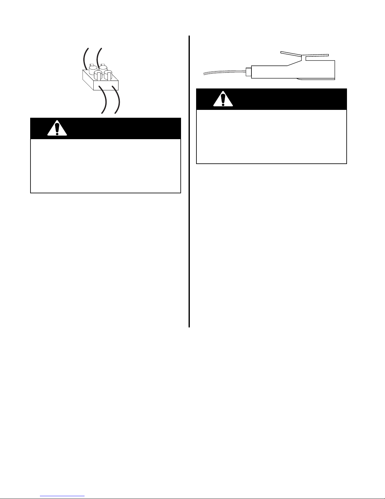
HOT SURFACE INDICATOR LIGHTS
WARNING
WARNING
Electrical Shock Hazard
Disconnect from electrical supply before servicing unit.
Failure to do so could result in electrical
shock or other personal injury.
Test Procedure
Refer to page 4-8 for the location of the hot
surface indicator lights and the procedure for
servicing them.
To test the hot surface indicator lights, perform the following steps:
1. Use a voltmeter and set it to read 120-volts
AC.
2. With power applied, measure across the
light terminals. If the reading is 0-volts,
check the wiring. If the meter reads 120volts AC, replace the hot surface indicator
light assembly.
SURFACE INDICATOR LIGHT
Electrical Shock Hazard
Disconnect from electrical supply before servicing unit.
Failure to do so could result in electrical
shock or other personal injury.
Test Procedure
Refer to page 4-4 for the location of the surface indicator lights and the procedure for
servicing them.
To test a surface indicator light, perform the
following steps:
1. Use a voltmeter and set it to read 120-volts
AC.
2. With power applied, measure across the
light terminals. If the reading is 0-volts, check
the wiring. If the meter reads 120-volts AC,
replace the indicator light.
5-2
Page 47
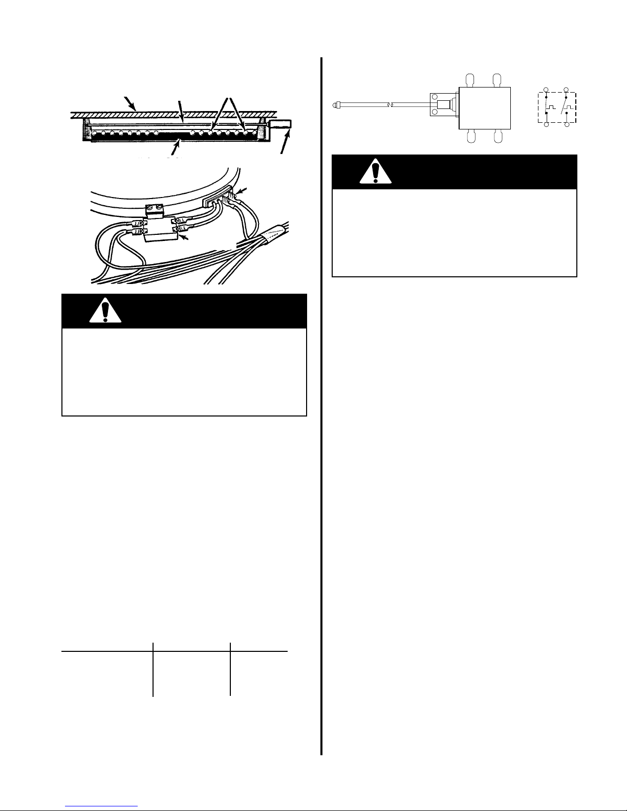
SURFACE ELEMENTS LIMITER
WARNING
MAINTOP SENSING ROD HEATING COIL
INSULATION LIMITER
ELEMENT
TERMINALS
Disconnect from electrical supply before ser-
LIMITER
TERMINALS
vicing unit.
Failure to do so could result in electrical
shock or other personal injury.
Test Procedure
2A 2B
1A
1B
Electrical Shock Hazard
2A 2B
1A
1B
WARNING
Electrical Shock Hazard
Disconnect from electrical supply before servicing unit.
Failure to do so could result in electrical
shock or other personal injury.
Test Procedure
Refer to page 4-8 for the location of the surface elements and the procedure for servicing
them.
To test a surface element, perform the following steps:
1. Use an ohmmeter and set the range switch
to R x 1.
2. With no power applied, disconnect one
wire from the element terminals.
3. Touch the ohmmeter leads to the element
terminals. You should obtain the following
readings for the indicated element:
Refer to page 4-8 for the location of the limiters.
To test a limiter, perform the following steps:
1. Use an ohmmeter and set the range to
R x 1.
2. With no power applied, touch the ohmmeter leads to the following terminals. You
should obtain the following readings:
1A and 2A are closed.
1B and 2B are open.
If the readings are not within the range shown,
the limiter is defective and should be replaced.
Element Location Resistance Power
Left Front 22 Ω ±5 2400 Watts
Left Rear 38 Ω ±5 1400 Watts
Right Front 32 Ω ±5 1700 Watts
Right Rear 26 Ω ±5 2100 Watts
If the resistance reading is not within the range
shown, the element is defective and should be
replaced.
5-3
Page 48
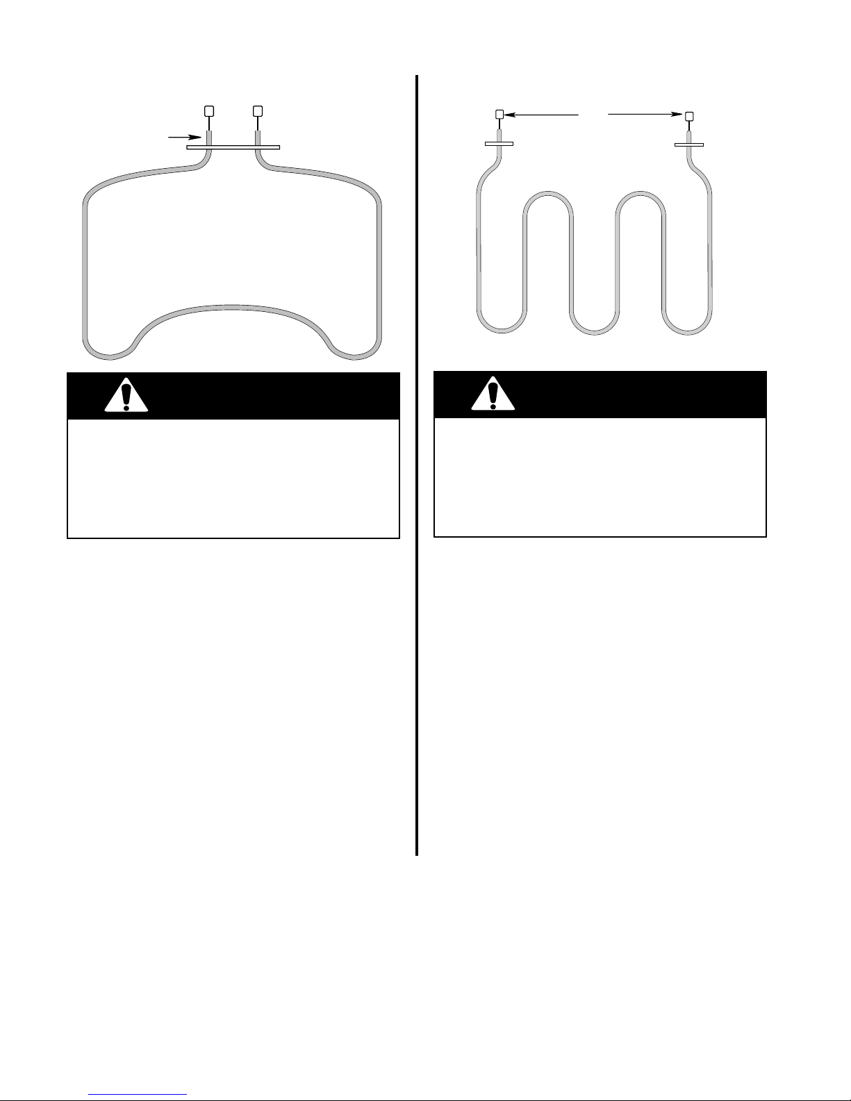
WARNING
BAKE
ELEMENT
WARNING
BROIL ELEMENTBAKE ELEMENT
Broil
Element
Terminals
Electrical Shock Hazard
Disconnect from electrical supply before servicing unit.
Failure to do so could result in electrical
shock or other personal injury.
Test Procedure
Refer to page 4-10 for the location of the
element and the procedure for servicing it.
To test the bake element, perform the following steps:
1. Use an ohmmeter and set the range switch
to R x 1.
2. With no power applied, disconnect one
wire from the element terminals. You
should obtain a reading of between 19 Ω
and 28 Ω.
If the reading is not within the range shown,
the element is defective, and should be replaced.
Electrical Shock Hazard
Disconnect from electrical supply before servicing unit.
Failure to do so could result in electrical
shock or other personal injury.
Test Procedure
Refer to page 4-10 for the location of the
element and the procedure for servicing it.
To test the broil element, perform the following steps:
1. Use an ohmmeter and set the range switch
to R x 1.
2. With no power applied, disconnect one
wire from the element terminals. You
should obtain a reading of between 17 Ω
and 26 Ω.
If the reading is not within the range shown,
the element is defective, and should be replaced.
5-4
Page 49
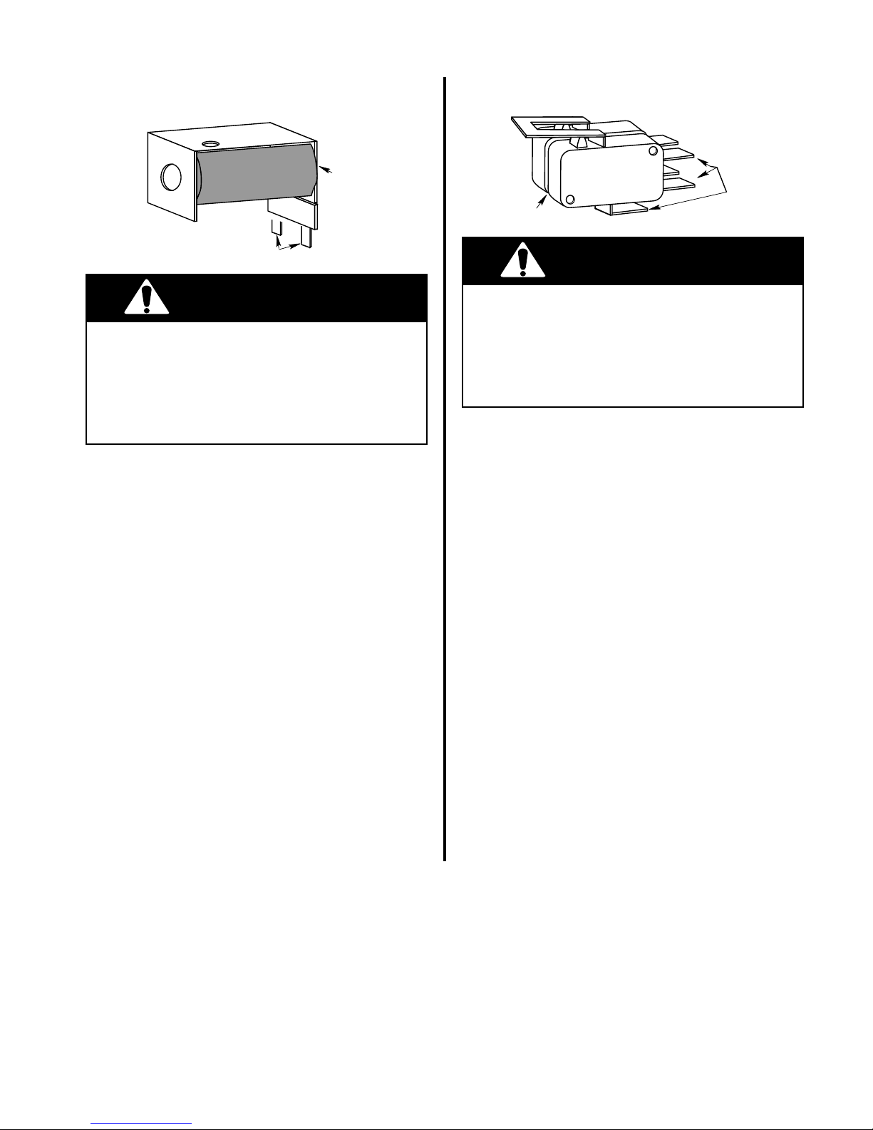
DOOR LOCK SOLENOID
WARNING
DOOR LATCH SWITCH
Solenoid
Rating: 120V, 60 Hz
Terminals
WARNING
Electrical Shock Hazard
Disconnect from electrical supply before servicing unit.
Failure to do so could result in electrical
shock or other personal injury.
Test Procedure
Refer to page 4-18 for the location of the door
lock solenoid and the procedure for servicing
it.
To test the solenoid windings, perform the following steps:
1. Use an ohmmeter and set the range switch
to R x 1.
2. With no power applied, remove the wire
from either solenoid terminal.
3. Touch the leads of the ohmmeter to the
terminals of the solenoid. You should obtain a reading of between 40 Ω and 65 Ω.
If the reading is not within the range shown,
the solenoid is defective and should be replaced.
NC
NO
COM
Switch
Electrical Shock Hazard
Disconnect from electrical supply before servicing unit.
Failure to do so could result in electrical
shock or other personal injury.
Terminals
Test Procedure
Refer to page 4-18 for the location of the door
latch switch and the procedure for servicing it.
To test the switch, perform the following steps:
1. With no power applied, remove the wires
from the door latch switch terminals.
2. Touch one of the ohmmeter leads to the
COM terminal and leave it there for steps
3 and 4.
3. Touch the other ohmmeter lead to the NO
terminal. The meter should indicate an
open (infinite ∞) circuit. Close the switch
and the ohmmeter should indicate 0 Ω
(closed circuit).
4. Touch the ohmmeter lead to the NC terminal. You should obtain a meter reading of
0 Ω. Close the switch and the meter should
indicate an open (infinite ∞) circuit.
If the above results are not obtained, the switch
is defective and should be replaced.
5-5
Page 50
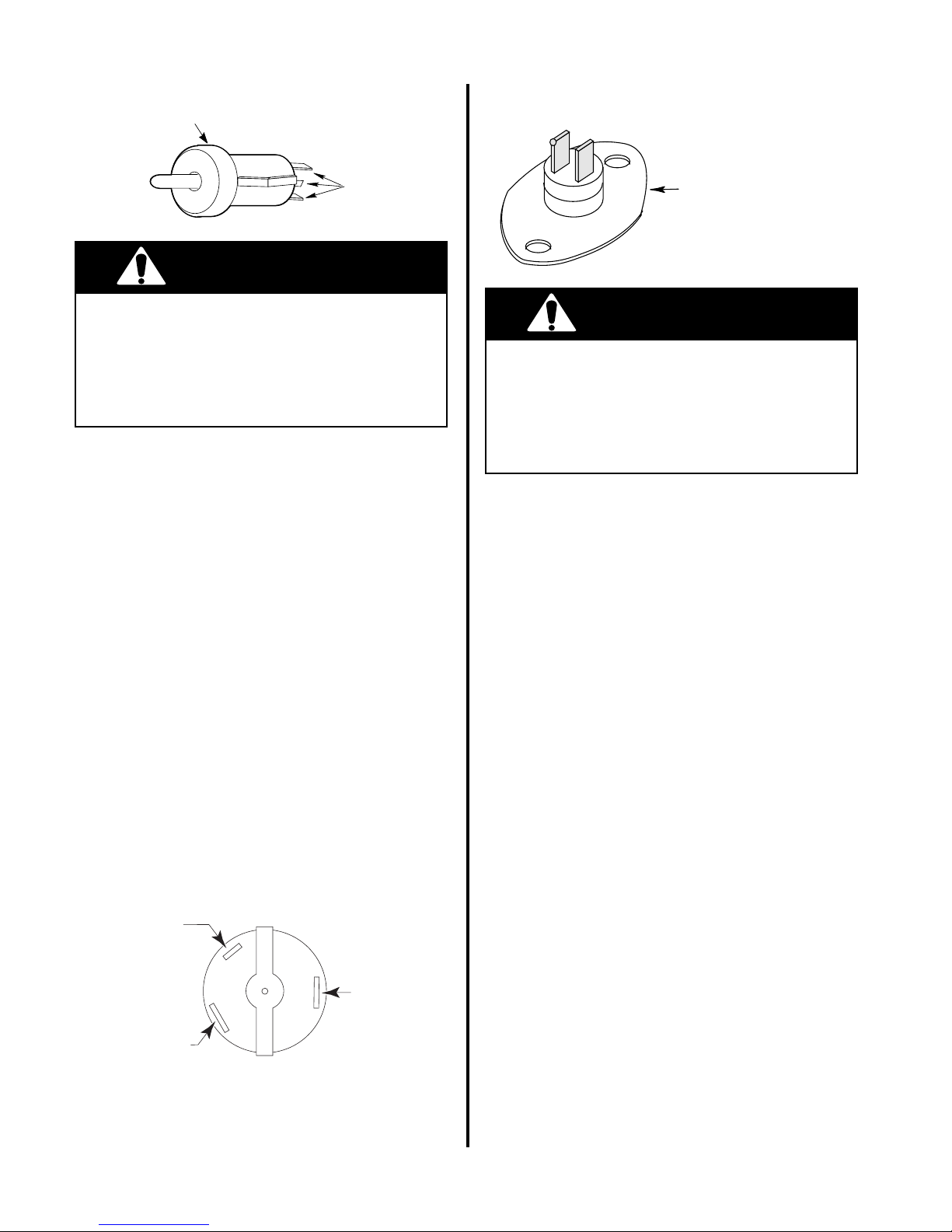
OVEN LIGHT SWITCH
WARNING
Oven Light
Switch
BIMETAL SWITCH
3 Terminals
WARNING
Electrical Shock Hazard
Disconnect from electrical supply before servicing unit.
Failure to do so could result in electrical
shock or other personal injury.
Test Procedure
Refer to page 4-14 for the location of the oven
light switch and the procedure for servicing it.
To test the oven light switch, perform the following steps:
1. Use an ohmmeter and set the range switch
to R x 1.
2. With no power applied, remove the wires
from the switch terminals.
3. Touch the leads of the ohmmeter to the
following terminal wires of the switch.
NOTE: A closed circuit = continuity (0 Ω),
an open circuit = infinite (∞):
Black & Red:
Door Closed = infinite.
Door Open = continuity.
Black & Yellow:
Door Closed = continuity.
Door Open = infinite.
Ambient Bimetal Switch &
Cooling Fan Bimetal Switch
(RESETTABLE)
Electrical Shock Hazard
Disconnect from electrical supply before servicing unit.
Failure to do so could result in electrical
shock or other personal injury.
Test Procedure
Refer to page 4-6 for the location of the bimetal
switches and the procedure for servicing them.
To test the two bimetal switches, perform the
following steps:
1. Use an ohmmeter and set the range switch
to R x 1.
2. With no power applied, touch the ohmmeter leads to the switch terminals as follows.
You should obtain the following readings
at the indicated temperatures:
Ambient Bimetal Switch
low the trip temperature of 203˚F.
Cooling Fan Bimetal Switch
the trip temperature of 104˚F.
If the reading is not within the range shown,
the switch is defective and should be replaced.
= continuity be-
= open below
Yellow
(Narrow Terminal)
Red
(Wide Terminal)
If the above results are not obtained, the switch
is defective and should be replaced.
Black
(Wide Terminal)
5-6
Page 51
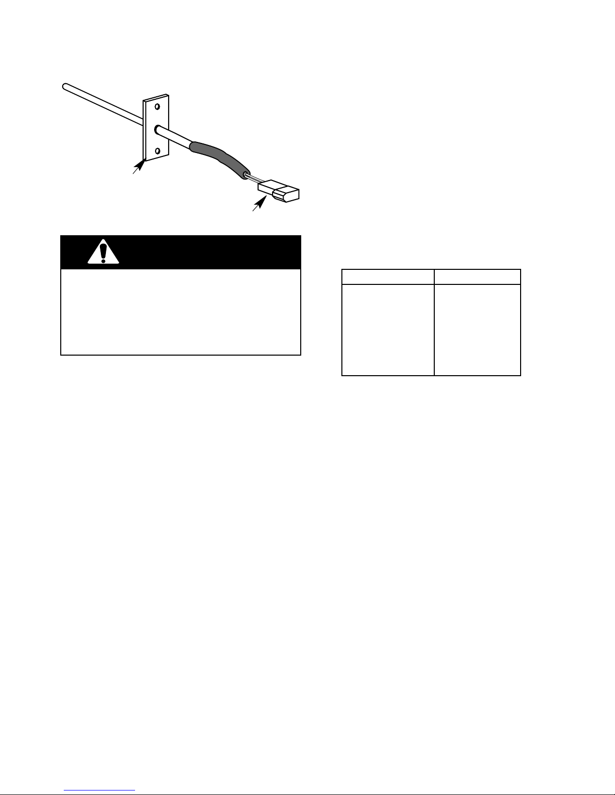
OVEN TEMPERATURE SENSOR
Oven Temperature
Sensor
2-Wire
Sensor Connector
WARNING
Electrical Shock Hazard
Disconnect from electrical supply before servicing unit.
Failure to do so could result in electrical
shock or other personal injury.
Test Procedure
Refer to page 4-18 for the location of the oven
temperature sensor and the procedure for servicing it.
To test the oven temperature sensor, perform
the following steps:
1. Use an ohmmeter and set the range switch
to R x 10.
2. With no power applied, touch the leads of
the ohmmeter to the connector pins of the
sensor (you do not have to separate the
connectors). Depending upon the oven
temperature, you should obtain the corresponding reading:
Temperature (˚F) Resistance (Ω)
32 ± 1.9 1000 ± 4.0
75 ± 2.5 1091 ± 5.3
250 ± 4.4 1453 ± 8.9
350 ± 5.4 1654 ± 10.8
450 ± 6.9 1853 ± 13.5
550 ± 8.2 2047 ± 15.8
650 ± 8.6 2237 ± 18.5
800 ± 13.6 2667 ± 24.4
If the reading is not within the range shown, the
sensor is defective and should be replaced.
5-7
Page 52

— NOTES —
5-8
Page 53
DIAGNOSIS & TROUBLESHOOTING
TROUBLESHOOTING CHART
WARNING
Electrical Shock Hazard
Certain procedures in this section require
electrical tests or measurements while power
is applied to the range. Exercise extreme
caution at all times. If test points are not
easily accessible, disconnect power, attach
test equipment, and reapply power to test.
PROBLEM SOLUTION
Clock display does not display 4
number eights after power-on
test.
Oven cooks but display does not
count down in cooking cycle.
Oven element emits black smoke
when first turned on.
Oven element does not heat.
POSSIBLE CAUSE
Loose or bad wiring.
Burned out or missing segment in
clock display.
Broken or missing terminal on
microcomputer.
Loose or bad wiring to harness.
Failed microcomputer board.
This is normal on a new range.
The factory-applied protective
coating is burning off.
Substance (e.g. food or other material) has spilled onto the element.
No line voltage.
Loose or bad wiring.
Repair or replace wiring (see
wiring diagrams).
Make sure clock display is properly seated.
Replace microcomputer board.
Repair or replace wiring (see
wiring diagrams).
Replace microcomputer board.
Protective coating will burn off in
several minutes. Fumes are nontoxic.
Let element cool then clean according to Use & Care instructions.
Check circuit breaker.
Repair or replace wiring (see
wiring diagrams).
Test and/or replace element.Defective element.
Cooktop element barely heats.
Low line voltage.
Loose or bad wiring connection at
element or terminal block.
Defective cooktop control switch.
6-1
Line voltage should be minimum
240-volts. If necessary, electrician should repair cause for low
line voltage.
Repair or replace wiring (see
wiring diagrams).
Test and/or replace switch.
Page 54
PROBLEM SOLUTIONPOSSIBLE CAUSE
Cooktop element will not heat
higher than low-medium.
Cooktop element heats up normally, but drops to lower setting
automatically.
Indicator light does not light up.
Hot surface indicator light does
not work.
Oven light fails to operate. Bulb burned out.
Low line voltage.
Defective cooktop element.
Customer using improper cookware.
Defective cooktop control switch.
Loose or bad wiring to indicator
light.
Defective indicator light.
Defective cooktop control switch.
Loose or defective light.
Loose or bad wiring to indicator
light assembly.
Circuit breaker or fuse is open.
Defective switch.
Line voltage should be minimum
240-volts. Electrician should repair cause for low line voltage.
Test and/or replace element.
Evaluate suitability of cookware.
Test and/or replace switch.
Repair or replace wiring (see
wiring diagrams).
Replace indicator light.
Test and/or replace switch.
Replace indicator light.
Replace indicator light assembly
and wiring.
Replace bulb.
Check circuit breaker or replace
fuse.
Check continuity and/or replace
switch.
Door locks but indicator lights do
not light. Oven does not begin
clean cycle.
programming.
Timer relay(s) do not close.
Oven will not bake (selection is
set for to BAKE).
set for TIMED BAKE).
Defective indicator light.
Defective latch safety switch.
Failed electronic board.Electronic timer will not accept
Loose or bad wiring to timer.
If indicator light lights up bake
element is defective.
Defective latch safety switch.
Loose or bad wiring.
Defective electronic clock.Oven will not bake (selection is
Replace indicator light.
Replace switch.
Replace timer.
Repair or replace wiring (see
wiring diagrams).
Replace timer.Failed electronic board.
Check and/or replace bake element.
Check continuity and/or replace
switch.
Repair or replace wiring (see
wiring diagrams).
Check continuity and/or replace
clock (see wiring diagrams).
6-2
Page 55
PROBLEM SOLUTIONPOSSIBLE CAUSE
Oven does not broil.
Oven door will not open or latch. Defective latch mechanism.
Overheating or “runaway” oven.
Premature burnout of bake element.
Door sagging on one side. Hinge loose or out of position to
If indicator light lights up broil
element is defective.
Defective latch safety switch.
Loose or bad wiring.
Defective (bent) door latch lever.
Cool-down period after self-clean
cycle not complete.
Loose or bad wiring to latch safety
switch.
Thermostat sensor bulb missing.
Improper use of oven (e.g. being
used to heat the home).
oven liner.
Check and/or replace broil element.
Check continuity and/or replace
switch.
Repair or replace wiring (see
wiring diagrams).
Replace mechanism.
Replace lever.
Wait until LOCK light goes out.
Repair or replace wiring (see
wiring diagrams).
Replace bulb.
Use oven for baking only.
Replace rollers.Worn or broken broil stop rollers.Oven door difficult to open.
Adjust hinges.
Door does not close completely
at top.
Door glass breaks.
Damaged oven door gasket. Improper cleaning. Do not use harsh abrasives or
Chipped oven liner. Damaged in shipping.
Oven racks fit too tight. Tolerance buildup in oven liner. Notify Customer Assurance De-
Broken or misadjusted door
spring.
Door fits too tight at bottom.
Broiling with door closed.
Oven racks covered with foil.
Glass installed backward.
Adjust or replace spring.
Adjust hinges outward.
Open door to broil stop position.
Do not cover racks with foil.
Install tempered glass toward the
heat.
scouring pads. See Use & Care
instructions.
Repair or replace liner. To repair
smooth porcelain bronzetone,
order P/N 242756.
partment.
6-3
Page 56

OVEN TEMPERATURE CALIBRATION
1. Press and hold the BAKE keypad for five
(5) seconds. The current offset, if any, will
be shown in the 3-digit display. CAL is
shown in the 4-digit display (3 digits on
right).
2. Pressing the TEMP keypad s up arrow
adjusts the temperature in 10˚F increments in the following sequence: 0˚, 10˚,
20˚, 30˚, -30˚, –20˚, –10˚, 0˚, and so on.
3. Press the START/ENTER keypad to activate the desired temperature adjustment.
If the START/ENTER keypad is not
pressed within 5 minutes, the adjustment
is ignored.
NOTE: The BAKE temperature adjustment cannot result in operating temperatures higher than
525˚F, or lower than 170˚F, as measured at
oven cavity center. Once the BAKE temperature has been adjusted, BROIL temperatures
are automatically offset to the same degree.
The CLEAN temperature is also offset automatically when the BAKE temperature is adjusted. If the BAKE temperature has been
raised, the CLEAN temperature is offset by
+5˚F. If the BAKE temperature has been lowered, the CLEAN temperature is offset to
–5˚F.
6-4
Page 57
NOTES:
OVEN CIRCUIT DIAGNOSIS CHART
1. All diagnoses of this range must begin with normal
check of line voltage, blown fuses, and failed
components.
2. All units that have failed during the first few days of
use should be checked for loose connections or
miswiring.
FAILURE / ERROR DISPLAY CODES
4-DIGIT
DISPLAY
F1
F2
F3
3-DIGIT
DISPLAY
EO
E1
E2
EO
E1
E0
E1
E2
E3
LIKELY
FAILURE
CONDITION
EEPROM
communications
EEPROM
checksum failure
UL A/D error(s)
Shorted key 1. Verify failure if not displayed, using CANCEL/OFF key.
Keytail unplugged
Oven sensor
opened
Oven sensor
shorted
Bake range over
temp
Clean range over
temp
1. Verify failure if not displayed, using CANCEL/OFF key. Press key for 5 seconds until
last error code is displayed
2. Disconnect power from oven for longer than 30 seconds.
3. Reapply power and observe for longer than 1 minute.
4. If failure remains, disconnect power, replace control, then go back to step 3.
2. Disconnect power.
3. If applicable, insure membrane tail seated in connector on back of control.
4. Reapply power and observe for longer than 1 minute.
5. If failure remains, disconnect power, replace control, then go back to step 4..
1. Measure sensor value (between connector pins) between 1000 Ω @32° F and
2697 Ω @ 900° F (approximately 1080 Ω @ room temperature).
If measurement does not correlate to real temperature, disconnect power,
replace sensor and refer to steps 3-5.
Also measure from sensor connector to sensor casing for possible short.
2. Trace wires and connectors to sensor, from control, then from sensor back to
control. If all connections made and no wire damage, refer to step 3.
3. Disconnect power for longer than 30 seconds.
4. Reapply power and observe for longer than 1 minute.
5. If failure remains, disconnect power, replace control, then go back to step 4.
SUGGESTED CORRECTIVE ACTION PROCEDURE
3. All checks should be made with a meter having
a sensitivity of 20,000 ohms-per-volt or greater.
E0
E1
Door and latch
switches do not
agree
Solenoid not
operating or latch
switch failure
F5
E2
Latch during
error
CLEAN
1. If door latched:
A) Disconnect power from unit.
B) Check wires and connectors from control to door switch, then from door
switch to control. If no damage to wires and all connectors okay, proceed to
step C.
C) Replace door switch.
D) Reapply power.
E) Press and hold any key down for 1 minute to clear -F5- failure code from memory.
-F2- will appear. Press CANCEL and observe for 1 minute to ensure operation
is correct.
2. If door not latched:
A) Disconnect power from unit.
B) Check wires and connectors from control to latch switch, then from latch switch
to control. If no damage to wires and all connectors okay, proceed to step C.
C) Repeat steps A) and B) for door switch.
3. Measure door switch (door open = switch open small low voltage terminals).
4. Measure latch switch (unlatch = switch open,
closed).
5. If corrections are made in any step, reconnect power to control. Press and hold any
key for 1 minute to clear -F- failure code from memory. -F2- will appear. Press
CANCEL
6. If failure remains, disconnect power, replace control.
and observe for 1minute to ensure operation is correct.
CAUTION
- oven light contacts are
6-5
Page 58

— NOTES —
6-6
Page 59
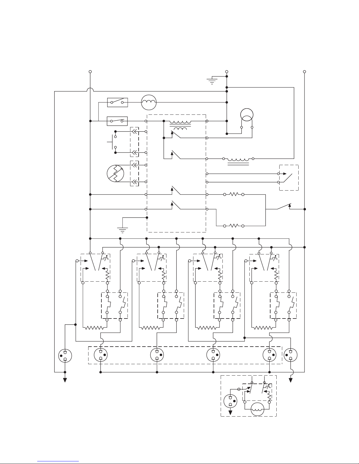
WIRING DIAGRAMS & STRIP CIRCUITS
WIRING DIAGRAM
L1
BK
GND
BI - METAL SW FAN N.O.
YY
BI-METAL SW
AMBIENT N.C.
BK
DOOR
SW.
OVE N
TEMP
SENSOR
W
BK
BK
G
GND
BK
BK
M
OVEN CONTROL
P4-3
Y
P3-3
Y
P3-4
V
P3-6
V
P3-7
P2-2
P2-3
OR P6
P3-5
W
TRANSFORMER
OVEN LIGHT
RELAY
LATCH RELAY
BROIL RELAY
BAKE RELAY
P4-1
P4-4
P4-5
P3-1
P3-2
P2-1
P2-4
W
R
DOOR LOCK
BR
BU
BU
V
R
SOLENOID
BROIL ELEMENT
BAKE ELEMENT
OVE N LT.
W
W
N.O.
COM
BU
R
DOOR
LATCH SW.
DLB RELAY
L2
R
R
BU
P
SURF
IND.
LIGHT
LF
H1 H2
BK
L2L1
BK
2A
1A 1B
2B
V
LF
P
H1 H2
Y
L2L1
LR
Y
2A
1A 1B
LR
V
HOT SURFACE
IND. LIGHTS
N
NOTES:
1.) Illustration shows door latch switch in COOK
position with oven door open and elements OFF.
2B
P
L1
RF
H1 H2
BR
BU
1A
2A
L2
BR
V
RF
SUR.
IND.
LIGHT
R
BU
RR
2A
1A
L2
H2
L2L1
BU
2B
1B
V
SURF
LIGHT
INF. SWITCH
(OPTIONAL)
COIL ELEMENT
IND.
N
P
H1 H2
R
2B
1B
RR
L1
P
H1
N
2.) Diagram shows Ceran models.
7-1
Page 60
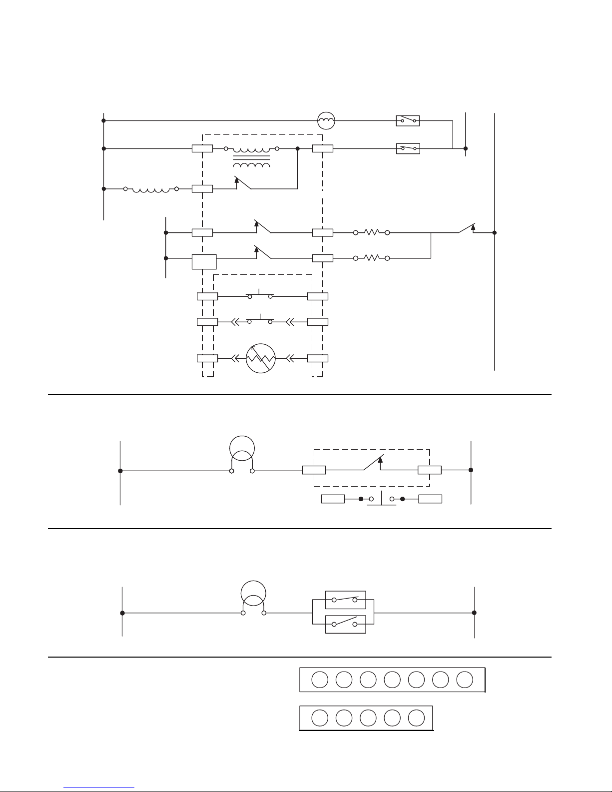
STRIP CIRCUITS
CLEAN (BAKE & BROIL RELAYS CYCLE)
BI - METAL SW FAN N.O.
Y
BK
BROIL ELEMENT
BAKE ELEMENT
BI - METAL SW
AMBIENT N.C.
R
Y
BK
DLB RELAY
L1
L2
R
W
W
W
LATCH
SOLENOID
L1
OVEN CONTROL
TRANSFORMER
LATCH RELAY
BROIL RELAY
BAKE RELAY
DOOR LATCH
BU
P3-1 P3-2
Y
P3-3 P3-4
V
P3-6 P3-7
SWITCH
DOOR SWITCH
SENSOR
BK
BK
BR
P4-1
P4-5
P2-2
P2-3
OR P6
BU
M
P4-3
BU
P2-1
R
P2-4
Y
V
N
OVEN LIGHT (U.S. MODELS)
OVEN LT.
W
OVEN LIGHT (CANADIAN MODELS)
N
W
OVEN LT.
QUICK DISCONNECT PLUGS
OVEN CONTROLN
R
P4-4 P4-3
P3
1
OVEN LIGHT RELAY
DOOR SW.
DOOR SW.
OVEN LIGHT SW.
BU BU Y Y G V V
NC
L1
BK
P3-4P3-3
L1
P4
WBKRBR
1
7-2
Page 61
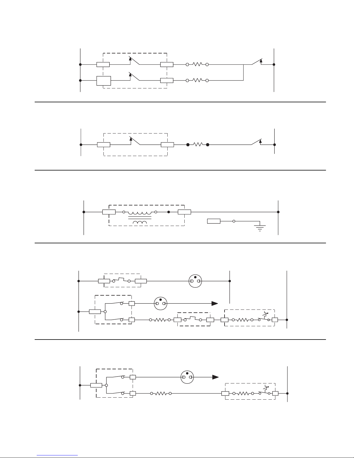
BAKE
BK
P2-2 P2-1
BK
P2-3
OR P6
BROIL
BK
P2-2 P2-1
CLOCK DISPLAY ON
OVEN CONTROLL1 L2
BROIL RELAY
BAKE RELAY
P2-4
BROIL ELEMENT
V
BAKE ELEMENT
R
R
DLB RELAY
R
OVEN CONTROLL1 L2
BROIL RELAY
BROIL ELEMENT
V
DLB RELAY
R
N L1
W
P4-1
OVEN CONTROL
TRANSFORMER
P4-3
P3-5
CERAMIC COOKTOP SURFACE UNIT (IF EQUIPPED)
L1
BK
BK
L1
LIMITER
2B
INFINITE SW.
LIMITER
H1
1B
SURFACE
IND. LIGHT
BU
P
SURFACE
ELEMENT
HOT SURFACE
IND. LIGHT
W
LIMITER
1A
W
N
2A H2
COIL COOKTOP SURFACE UNIT (IF EQUIPPED)
L1 L2
BK
INFINITE SW.
L1
FRONT/REAR
P
BK/BU
H1 L2
SURFACE
ELEMENT
SURFACE
IND. LIGHT
W
N
H2
BK
L2
INFINITE SW.
INFINITE SW.
GND
G
L2
R
L2
R
7-3
Page 62

— NOTES —
7-4
Page 63
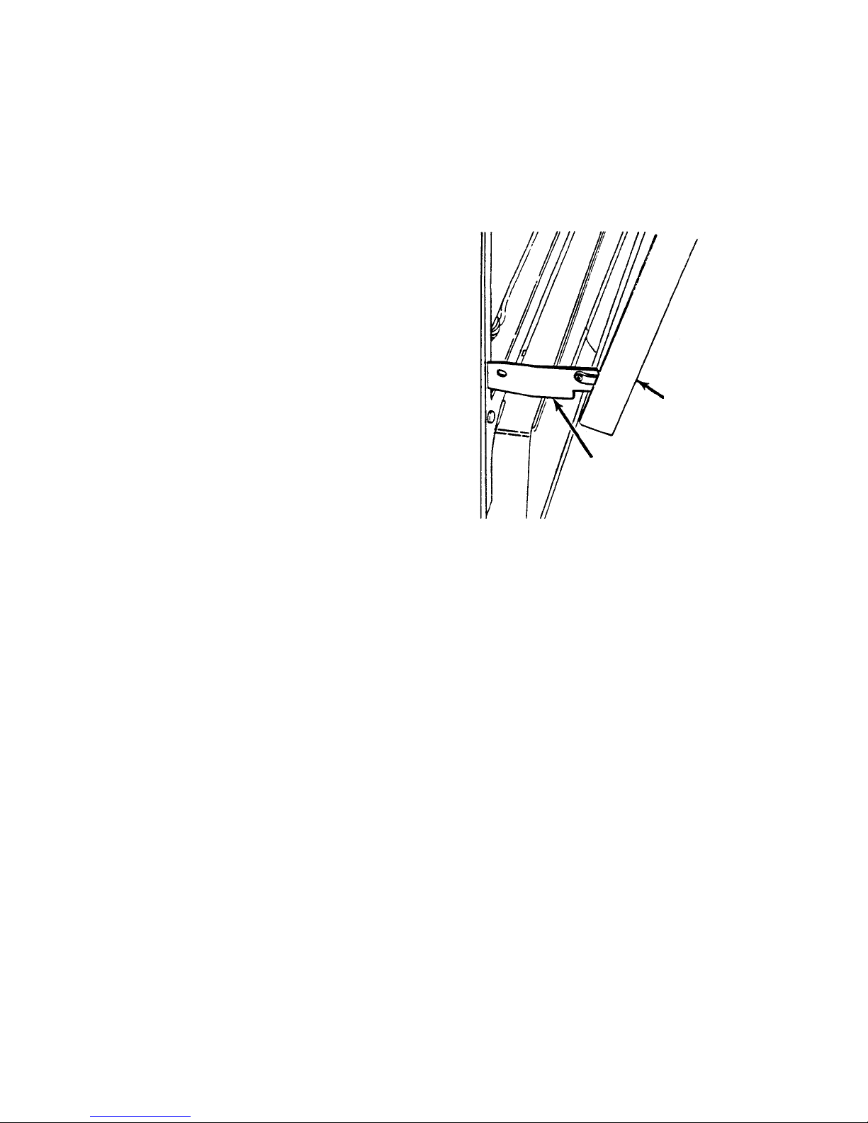
TECH TIPS
REMOVING THE OVEN DOOR
Refer to the illustration for the following steps.
1. Open the oven door to the first (broil) stop.
2. Grasp the oven door on both sides. Simultaneously lift straight up and pull out on the
door for approximately two inches to release the hinge brackets from the hinge
stops.
3. Close the door completely so it is perpendicular to the floor, then pull the door out of
the oven tracks.
Oven Door
Door Hinge
8-1
Page 64

REQUESTING ASSISTANCE OR SERVICE
To avoid unnecessary service calls, please
check the “Troubleshooting” section of your Use
and Care Guide. It may save you the cost of a
service call. If you still need help, follow the
instructions below.
1. If the problem is not due to one of the
items listed in the “Troubleshooting”
section of your Use and Care Guide*:
Call the Whirlpool or Inglis Limited Consumer Assistance Center telephone number. Dial toll-free from anywhere:
In the U.S.A. — Call 1-800-253-1301
In Canada — Call 1-800-461-5681
8:30 a.m. - 6:00 p.m. (EST)
One of our trained consultants can instruct
you in how to obtain satisfactory operation
from your appliance or, if service is necessary, recommend a qualified service company in your area.
If you prefer, write to:
In the U.S.A. — Whirlpool Brand Home
Appliances Consumer Assistance Center
c/o Correspondence Department
2000 North M-63
Benton Harbor, MI 49022-2692
In Canada — Consumer Relations Department
Inglis Limited
1901 Minnesota Court
Mississauga, Ontario L5N 3A7
Please include a daytime phone number in your
correspondence.
2a.If you need service in the U.S.A.*:
Whirlpool has a nationwide network of designated Whirlpool service companies. Whirlpool designated service technicians are
trained to fulfill the product warranty and
provide after-warranty service, anywhere
in the United States. To locate the designated Whirlpool service company in your
area, call our Consumer Assistance Center
telephone number (see Step 1) or look in
your telephone directory Yellow Pages under:
• APPLIANCE-HOUSEHOLD MAJOR,
SERVICE & REPAIR (See “Whirlpool
Appliances or Authorized Whirlpool
Service—Example:
• WASHING MACHINES & DRYERS,
SERVICE & REPAIR (See “Whirlpool
Appliances or Authorized Whirlpool
Service—Example:
2b.If you need service in Canada*:
Contact “Inglis Limited Appliance Service”
from anywhere in Canada at — 1-800-807-
6777.
3. If you need FSP® replacement parts:
FSP® is a registered trademark of Whirlpool
Corporation for quality parts. Look for this
symbol of quality whenever you need a
replacement part for your whirlpool appliance. FSP replacement parts will fit right
and work right because they are made to
the same exacting specifications used to
build every new Whirlpool appliance.
To locate FSP replacement parts in your
area, refer to Step 2 or call the Consumer
Assistance Center number (see Step 1).
* When asking for help or service: Please
provide a detailed description of the problem, your appliance’s complete model and
serial numbers, and the purchase date.
(See the “A Note to You” section of your
Use and Care Guide.) This information will
help us respond properly to your request.
XYZ Service Co.
XYZ Service Co.
)
)
8-2
Page 65
WHIRLPOOL ELECTRIC RANGE WARRANTY
LENGTH OF
WARRANTY:
ONE-YEAR FULL
WARRANTY
FROM DATE OF
PURCHASE.
WHIRLPOOL
WILL PAY FOR:
®
FSP
replacement
parts and repair
labor costs to
correct defects in
materials or workmanship. Service
must be provided
by an authorized
Whirlpool service
company.
WHIRLPOOL
WILL NOT PAY FOR:
A. Service calls to:
1. Correct the installation of the range.
2. Instruct you how to use the range.
3. Replace house fuses or correct house wiring.
4. Replace owner-accessible light bulbs.
5. Correct house plumbing.
B. Repairs when the range is used in other than
normal, single-family household use.
C. Pickup and delivery. The range is designed to
be repaired in the home.
D. Damage to the range caused by accident, alter-
ation, misuse, abuse, fire, flood, acts of God, or
use of products not approved by Whirlpool.
E. Repairs to parts or systems resulting from unau-
thorized modifications made to the appliance.
F. In Canada, travel or transportation expenses for
customers who reside in remote areas.
G. Replacement parts or repair labor costs for units
operated outside the United States and Canada.
WHIRLPOOL CORPORATION AND INGLIS LIMITED SHALL NOT BE LIABLE FOR INCIDENTAL OR CONSEQUENTIAL DAMAGES. Some states or provinces do not allow the exclu-
sion or limitation of incidental or consequential damages, so this exclusion or limitation may not
apply to you. This warranty gives specific legal rights and you may also have other rights which
vary from state to state or province to province.
Outside the United States and Canada, a different warranty may apply. For details, please
contact your authorized Whirlpool dealer.
If you need service, refer to the “Requesting Assistance or Service” section on the previous page.
After checking “Requesting Assistance or Service,” additional help can be found by calling the
Whirlpool Consumer Assistance Center telephone number, 1-800-253-1301, from anywhere in
the U.S.A. In Canada, contact your authorized Inglis Limited Appliance Service company, 1-800-
807-6777.
8-3
Page 66

— NOTES —
8-4
 Loading...