

Page 1

Have questions about your dryer?
Check your Use and Care Guide for a toll-free number to call, or call your
dealer. The dealer is listed in the Yellow Pages of your phone directory
under “Appliances — Household — Major — Service and Repair.”
When you call, you will need the dryer model number and serial number.
Both numbers are on the model/serial rating plate located in the door well
behind the dryer door and on front of opening.
Record the numbers here for handy reference:
Model No.
Serial No.
Moving dryer to a new location?
Check with a licensed electrician to confirm that supply voltage at new home matches
voltage specified on the model/serial rating plate.
Shut off electrical
supply to dryer.
Unplug power supply
cord and tape it
securely to dryer.
(Or disconnect power
supply cable from
dryer.)
Tape top
to cabinet.
Tape door to
front panel.
Turn leveling
legs all the
way in.
Slide dryer onto cardboard or hardboard
before moving it across the floor to
prevent damaging floor covering.
Installation Instructions
Electric Dryer
Part No. 3979171
IMPORTANT:
Read and save these instructions.
Installer: Leave Installation Instructions with homeowner.
Homeowner: Keep Installation Instructions for future reference.
For best performance, install dryer according to
Installation Instructions. Failure to complete installation
as instructed could void warranty.
Save Installation Instructions for local electrical inspector’s use.
Page 2
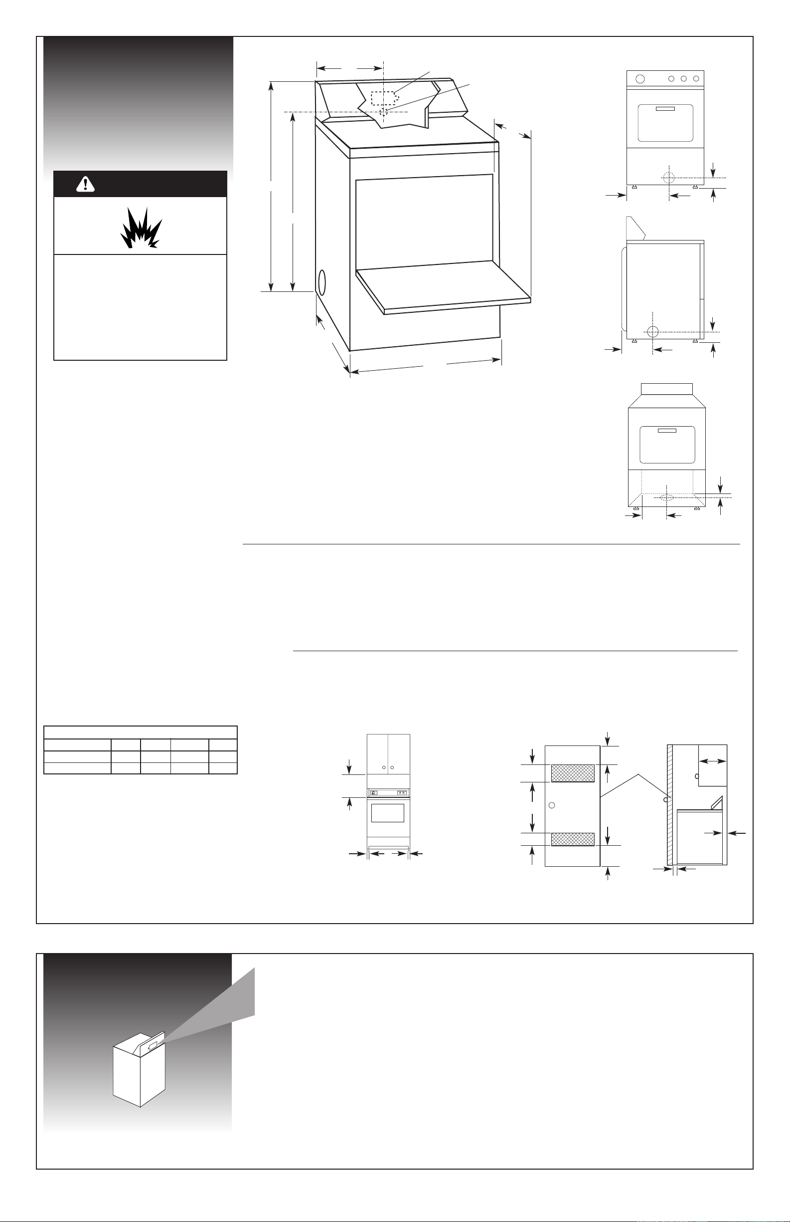
Recessed area/closet installation
The dryer
door
extends
14" from
the front
of the
dryer
when fully
opened.
Dryer location
and dimensions
The location must provide:
✔Protection from weather and water: Do not
store or use dryer where it will be exposed to
water and weather.
✔Room temperature above 45°F: If room
temperature is below 45°F, automatic cycles may
not shut off.
3"
3"
48
sq. in.
**
24 sq. in.
**
0"***
14"
max.
front view
1"
closet
door
** Minimum top and bottom air openings for closet door.
*** External exhaust elbow requires additional space.
Recessed area installation
0"*
0"*
front view
15"
Closet/confined area installation
If a closet door is installed: The minimum
unobstructed air openings are required. Louvered
doors with equivalent air openings are acceptable.
*
Wall, door and floor molding may require
additional spacing.
terminal block cover
power supply
cord/cable
strain relief
side view
For proper drying performance:
It is your responsibility to:
Panel A
Recessed
Closet
Back
5"/0"
5"/0"
Sides
1"/0"
1"/0"
Top
18"/15"
18"/15"
Front
—
1"/1"
WARNING — To reduce the risk of fire this appliance
MUST BE EXHAUSTED OUTDOORS
Installation clearances
Use recommended clearance for easier installation.
Recommended/Minimum
Explosion Hazard
Keep flammable materials and
vapors, such as gasoline, away from
dryer.
Place dryer at least 18 inches above
the floor for a garage installation.
Failure to do so can result in death,
explosion, or fire.
WARNING
Electrical
requirements
Recommended ground method
It is the personal responsibility and obligation of the
customer to contact a qualified electrician to assure
that the electrical installation is adequate and is in
conformance with the National Electrical Code,
ANSI/NFPA 70 — latest edition**** and all local
codes and ordinances.
Copies of the standards listed above may be obtained
from:
****National Fire Protection Association
Batterymarch Park
Quincy, Massachusetts 02269
• A clothes dryer produces combustible lint and
must be exhausted outdoors.
• If codes permit, dryer may be installed in a
recessed area or closet using dimensions shown.
• Dimensions are in inches and are the minimum
allowable.
• Additional spacing should be considered for ease
of installation and servicing. Companion
appliance spacing should also be considered.
✔Observe all governing codes and ordinances.
✔Check code requirements: Some codes limit or
do not permit installation of clothes dryers in
garages, closets, mobile homes or sleeping
quarters. Contact your local building inspector.
Important: Observe all governing codes and
ordinances.
A four-wire or three-wire, single phase, 120/240volt, 60-Hz, AC-only, electrical supply (or four-wire
or three-wire, 120/208-volt if specified on
model/serial rating plate) is required on a separate
30-ampere circuit, fused on both sides of the line. A
time-delay fuse or circuit breaker is recommended.
If codes permit and a separate ground wire is
used, it is recommended that a qualified electrician
determine that the ground path is adequate.
✔Comply with the installation specifications and
dimensions.
✔Consider spacing requirements for companion
appliances.
✔Make sure you have everything necessary for proper
installation.
✔Properly install dryer.
✔Contact a qualified installer to insure that the
electrical installation meets all national and local
codes and ordinances.
43-1/8"
11"
38-1/4"
✔Level floor: Maximum slope under entire dryer
should not be more than 1 inch. (If slope is greater
than 1 inch, install Extended Dryer Feet Kit, Part
No. 279810.) Clothes may not tumble properly and
automatic sensor cycles may not operate correctly if
dryer is not level.
✔Sturdy floor to support dryer weight of
120 pounds.
27”
Dimensions shown with feet extended 1” from bottom of dryer.
14-1/8"
7-1/4"
left or right
side exhaust
bottom exhaust
back exhaust
4-1/4"
10-1/4"
14-1/8"
4"
Exhaust dimensions
14"
29-1/4"* (models with flush
mounted door handle)
30-1/4"* (models with
extended door handle)
*Most models will require at least 5" clearance behind the dryer for the dryer vent.
Page 3
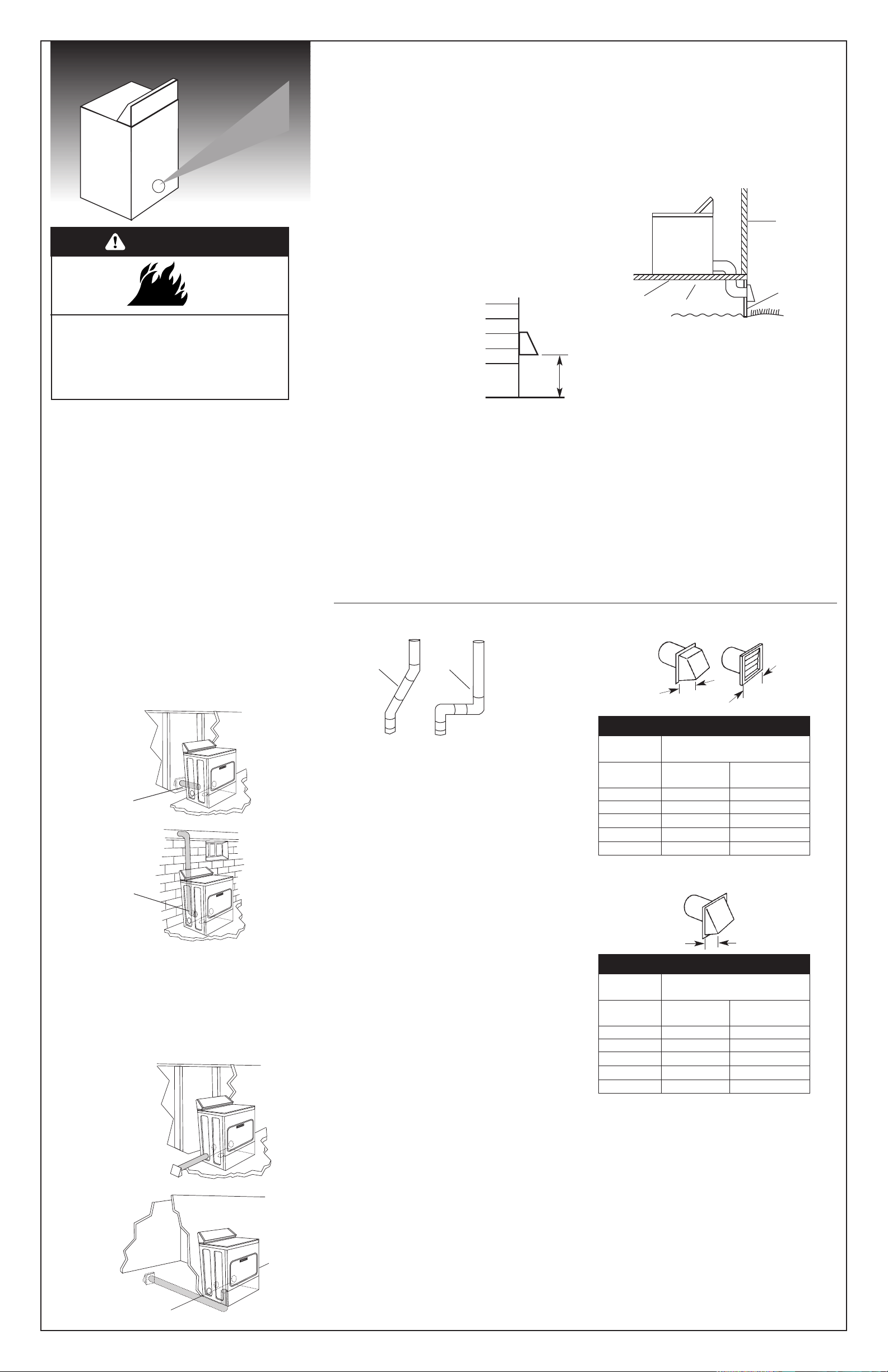
Exhaust requirements
Typical installations
exhaust from the
rear of the dryer.
better
exhaust air flow
acceptable
The maximum length of the exhaust system depends
upon:
• the type of vent (rigid or flexible metal).
• the number of elbows used.
• side or bottom exhaust. Side or bottom exhaust
adds a 90° turn inside the dryer. To determine
maximum exhaust length, add one 90° turn to the
chart.
1. See the exhaust vent length chart that matches
your type hood for the maximum vent lengths you
can use.
Do not use vent runs longer than specified in
exhaust vent length charts.
Exhaust systems longer than specified will:
— accumulate lint creating a potential fire
hazard.
— shorten the life of the dryer.
— reduce performance, resulting in longer
drying times and increased energy usage.
2. Determine the number of elbows you will need.
3. In the column listing the type of metal vent you are
using (rigid or flexible), find the maximum length
of metal vent on the same line as the number of
elbows.
4. Determine the number of 4" clamps you will need.
The maximum length using a 2" x 6" rectangular
vent with 2 elbows and a 2-1/2" exhaust hood is
8 ft.
Mobile home installation requirements
If codes permit, this appliance is suitable for mobile
home installations. The installation of the dryer must
conform to Manufactured Home Construction and
Safety Standard, Title 24 CFR, Part 3280 (formerly the
Federal Standard for Mobile Homes Construction and
Safety, Title 24, HUD Part 280) or latest edition.
The dryer must be exhausted outside.
skirting
enclosed area
outside
wall
floor
Plan the exhaust vent installation
Select the route that will provide the straightest
and most direct path outdoors. Plan the installation
to use the fewest number of elbows and turns.
When using elbows or making turns, allow as much
room as possible. Bend vent gradually to avoid
kinking.
For exhaust systems not covered by exhaust vent
length charts (such as multiple unit hookups,
plenums, and power-assist fans), see Service
Manual, Part No. 603197. (To purchase the Service
Manual, see your Use and Care Guide for a toll-free
telephone number.)
Route the vent
Determine exhaust vent length
Panel B
2-1/2"
Acceptable —
4"
4"
Preferred —
This dryer may be converted to exhaust
out the right or left side or through the bottom.
To convert the dryer, the following kits are available
from your dealer:
Exhaust Kit No. 279818 (white)
Exhaust Kit No. 279819 (almond)
Exhaust Kit No. 279925 (biscuit)
Exhaust Kit No. 279969 (silver)
Fire Hazard
Use a heavy metal vent.
Do not use a plastic vent.
Do not use a metal foil vent.
Failure to do so can result in death or fire.
WARNING
Typical installations
for left or right side
exhausting.
Typical installations
for bottom
exhausting.
straight back
offset
Important: Observe all governing codes and
ordinances.
It is recommended that you exhaust your dryer to
the outside for best performance. Moisture and lint
indoors may cause:
• Lint to gather around the dryer where it can be fuel
for a fire.
• Moisture damage to woodwork, furniture, paint,
wallpaper, carpet, etc.
• Housecleaning problems and health problems.
Dura Safe
™
venting products are recommended
and are available from your dealer.
Four-inch diameter vent must be used.
Use a heavy metal vent. Do Not use plastic or metal
foil vent.
• Do Not use non-metal flexible vent, or exhaust
hoods with magnetic latches.
• Do Not exhaust dryer into a chimney, wall, ceiling,
furnace, cold air vent, duct, concealed space, attic
or crawl space, or any other vent used for venting.
• Do Not install flexible vent in enclosed walls,
ceilings or floors.
Rigid metal vent is recommended to prevent
crushing and kinking.
Flexible metal vent must be fully extended and
supported when the dryer is in its final position.
Remove excess flexible vent to avoid sagging and
kinking that may result in reduced air flow.
An exhaust hood should cap
the exhaust vent to prevent
rodents and insects from entering
the home.
Exhaust outlet hood must be at
least 12 inches from the ground or
any object that may be in the path
of the exhaust (such as flowers,
rocks or bushes, etc.).
If using an existing exhaust
system, clean lint from entire
length of system and make sure exhaust hood is
not plugged with lint. Replace any plastic or metal
foil vent with rigid metal or flexible metal vent.
Use clamps to seal all joints. Do Not use duct tape,
screws or other fastening devices that extend into the
interior of the vent to secure vent.
12" min.
The exhaust vent must be securely fastened to a
non-combustible protion of the mobile home
structure and must not terminate beneath the
mobile home.
Maximum length of
4" diameter metal vent
When you have a 4" hood …
Number of
90° elbows
0
1
2
3
4
Rigid
64 ft.
54 ft.
44 ft.
35 ft.
27 ft.
Flexible
(fully extended)
36 ft.
31 ft.
27 ft.
25 ft.
23 ft.
Maximum length of
4" diameter metal vent
When you have a 2-1/2" hood …
Number of
90° elbows
0
1
2
3
4
Rigid
58 ft.
48 ft.
38 ft.
29 ft.
21 ft.
Flexible
(fully extended)
28 ft.
23 ft.
19 ft.
17 ft.
15 ft.
The exhaust outlet is located at the center of the
rear of the dryer.
The exhaust vent can be routed up, down, left,
right or straight out the back of the dryer. See
“Recessed area/closet installation” section, Panel A,
for general space requirements.
Page 4
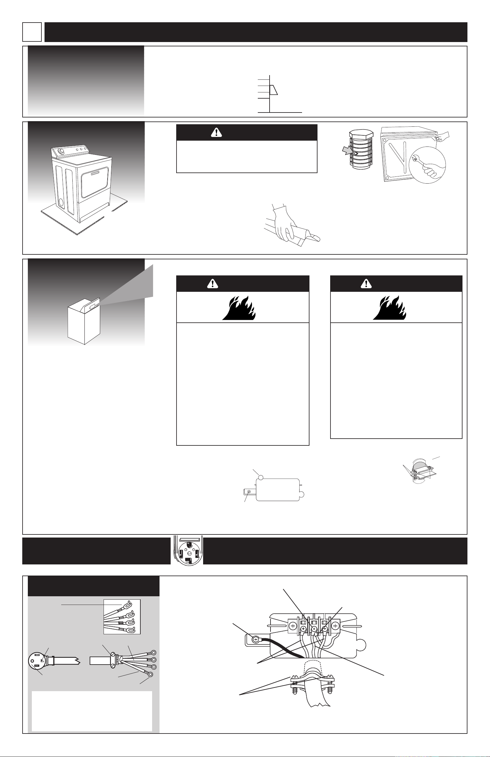
A. Install vent
system (new
installation)
B.
Prepare dryer
1. Put on safety glasses and gloves.
3. Connect vent to exhaust hood with 4"
clamp. (Exhaust vent MUST fit inside hood.)
4. Run exhaust vent to dryer location.
Use the straightest path possible. (See Panel B.)
Use clamps to secure vent pieces. Tin snips may be
needed to cut vent to required length.
1. Open dryer door and drying rack, if included.
Wipe drum with damp cloth to remove any dust.
2. Take two cardboard
corners from dryer carton and
place them on floor in back of
dryer. Firmly grasp body of dryer
and gently lay it on its back on the
cardboard corners.
diamond
marking
3. Start to screw legs into holes by hand. Use
an adjustable wrench or 1" hex-head socket wrench
to finish turning legs until you reach the ridge with
the diamond marking.
4. Stand dryer up on cardboard or hardboard.
Now start installation
(If installing washer and dryer, install dryer first.)
✔
2. Install exhaust hood.
Use caulking compound to seal
exterior wall opening around
exhaust hood.
Panel C
3. Assemble 3/4"
U.L.-listed strain relief
(U.L. marking on
strain relief) into the
hole below terminal block
opening. Tighten strain relief
screws just enough to hold
the two clamp sections together. Install power
supply cord/cable through the strain relief.
C. Electrical
connection
GROUNDING INSTRUCTIONS: This appliance must
be grounded. In the event of malfunction or
breakdown, grounding will reduce the risk of
electric shock by providing a path of least
resistance for electric current.
If using a power supply cord, the plug must be
plugged into an appropriate outlet that is properly
installed and grounded in accordance with all local
codes and ordinances.
If using a direct wire connection, this appliance
must be connected to a grounded metal,
permanent wiring system; or an equipmentground conductor must be run with the circuit
conductors and connected to the equipmentground terminal or lead on the appliance.
WARNING - Improper connection of the
equipment-grounding conductor can result in a
risk of electric shock. Check with a qualified
electrician or serviceman if you are in doubt as to
whether the appliance is properly grounded. Do
not modify the power supply cord plug. If it will
not fit the outlet, have a proper outlet installed by
a qualified electrician.
Complete installation following instructions for
your type of connection:
• Four-wire (recommended method)
• Three-wire (if four-wire is not available)
1. Disconnect the power supply.
2. Remove hold-down
screw and terminal
block cover.
Power supply cord
Direct wire
This dryer is manufactured with the cabinetground conductor connected to the NEUTRAL
(center) of the wiring harness at the terminal
block. If local codes do NOT permit this type of
connection, use “Four-wire connection”
instructions.
rear
panel
strain relief
screws
strain
relief
clamp
sections
terminal
block
cover
hold-down screw
external ground
conductor screw
SLIDE DRYER ONTO
CARDBOARD OR
HARDBOARD BEFORE
MOVING ACROSS
FLOOR TO PREVENT
FLOOR DAMAGE.
Excessive Weight Hazard
Use two or more people to move and install dryer.
Failure to do so can result in back or other injury.
WARNING
Four-wire connection...
Four-wire power supply cord at least four feet
long must have four, No.-10 copper wires and
match a four-wire receptacle of NEMA Type
14-30R. The fourth wire (ground conductor)
must be identified with a green cover and the
neutral conductor by a white cover.
NEUTRAL
NEUTRAL (white)
3/4" U.L.-listed
strain relief
ground prong
ground wire
(green)
ring terminals
spade
terminals with
upturned ends
4. Remove center terminal block screw.
6. Connect ground wire
(green) of power supply cord to
external ground conductor
screw. Tighten screw.
external ground
connection
7. Connect neutral
wire (white or center)
of power supply cord
under center screw of
the terminal block.
Tighten screw.
8. Connect the other wires to
outer terminal block screws.
Tighten screws.
9. Tighten strain
relief screws.
10. Insert tab of terminal block cover
into slot of the dryer rear panel. Secure
cover with hold-down screw.
5. Remove appliance ground wire (green
with yellow stripes) from external ground
connector screw. Fasten under center,
silver-colored terminal block screw.
POWER SUPPLY CORD
14-30R Four-wire receptacle (required for mobile homes)
Fire Hazard
Use a new UL approved 30 ampere power
supply cord.
Use a UL approved strain relief.
Disconnect power before making electrical
connections.
Connect neutral wire (white or center wire)
to center terminal (silver).
Ground wire (green or bare wire) must be
connected to green ground connector.
Connect remaining 2 supply wires to
remaining 2 terminals (gold).
Securely tighten all electrical connections.
Failure to do so can result in death, fire, or
electrical shock.
Fire Hazard
Use 10 gauge solid copper wire.
Use a UL approved strain relief.
Disconnect power before making electrical
connections.
Connect neutral wire (white or center wire)
to center terminal (silver).
Ground wire (green or bare wire) must be
connected to green ground connector.
Connect remaining 2 supply wires to
remaining 2 terminals (gold).
Securely tighten all electrical connections.
Failure to do so can result in death, fire, or
electrical shock.
WARNING WARNING
Page 5
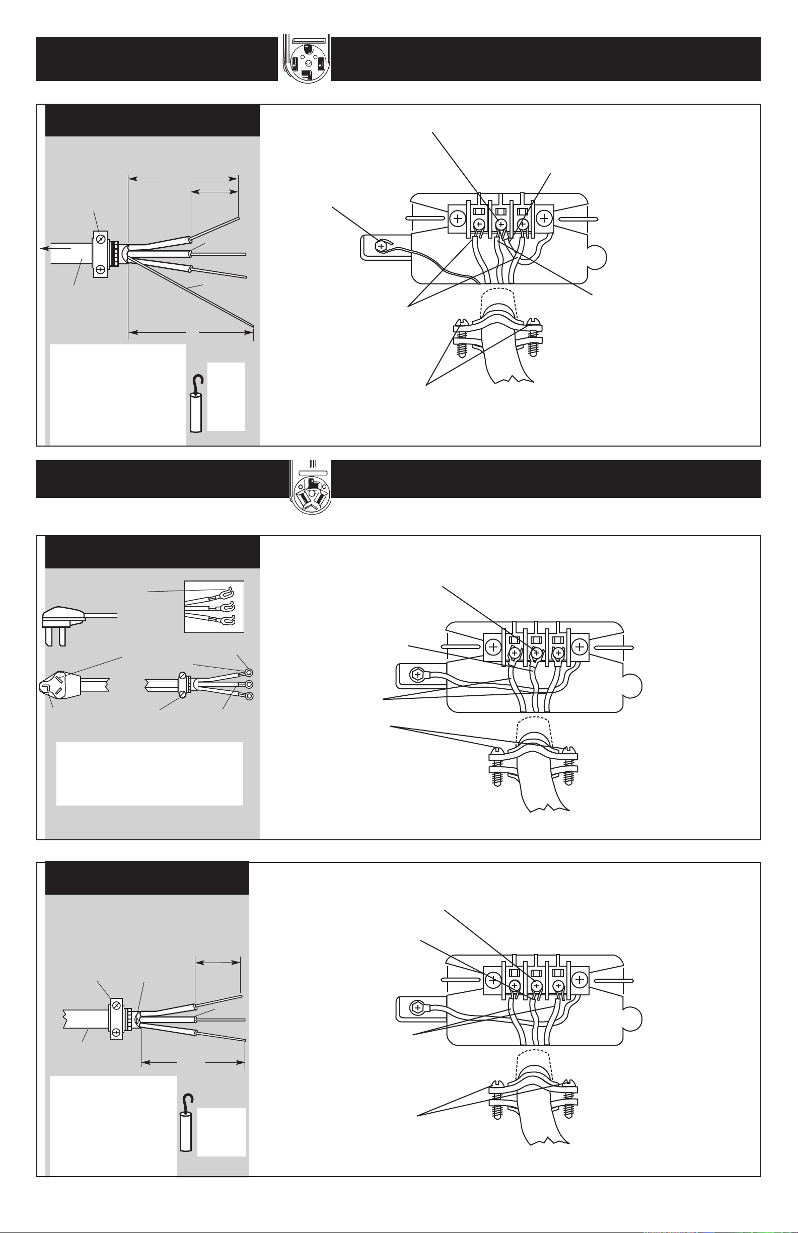
4. Remove center terminal block screw.
7. Place the hooked end
of the neutral wire (white
or center) of power
supply cable under the
center screw of terminal
block (hook facing right).
Squeeze hook end
together. Tighten screw.
8. Place the hooked ends of the
other power supply cable wires
under the outer terminal block
screws (hook facing right). Squeeze
hooked ends together. Tighten
screws.
6. Connect the ground wire
(bare) of the power supply
cable to the external ground
conductor screw. Tighten
screw.
10. Insert tab of terminal block cover
into slot of dryer rear panel. Secure cover
with hold-down screw.
9. Tighten strain relief screws.
5. Remove appliance ground wire (green
with yellow stripes) from external ground
connector screw. Fasten under center,
silver-colored terminal block screw.
DIRECT WIRE
Preparing the wire:
3/4" U.L.listed strain
relief
to
disconnect
box
NEUTRAL wire
(white or center)
10-gauge, 3-wire
with ground wire
(Romex)
5"
3-1/2"
1" of wires
stripped of
insulation
bare ground
wire
Direct wire cable must have
four feet of extra length so
dryer can be moved if needed.
Strip 5 inches of outer covering
from end of cable. Leave bare
ground wire at 5 inches. Cut
1-1/2 inches from 3 remaining
wires. Strip insulation back
1 inch.
Shape
ends
of
wires
into a
hook.
Panel D
Three-wire power supply cord at least four
feet long must have three, No.-10 copper
wires and match a three-wire receptacle of
NEMA Type
10-30R.
4. Loosen or remove center terminal
block screw.
6. Connect the other
wires to outer terminal
block screws. Tighten
screws.
7. Tighten strain relief
screws.
8. Insert tab of terminal block cover
into slot of dryer rear panel. Secure
cover with hold-down screw.
5. Connect the neutral wire (white
or center) of power supply cord to
the center, silver-colored terminal
screw of the terminal block.
Tighten screw.
POWER SUPPLY CORD
Three-wire connection...
NEUTRAL
NEUTRAL
(white or center)
3/4" U.L.-listed
strain relief
This blade connected
to this conductor.
ring
terminals
spade
terminals with
upturned ends
Where local codes permit
connecting cabinet-ground conductor to neutral wire:
10-30R Three-wire receptacle
Four-wire connection...
14-30R Four-wire receptacle (required for mobile homes)
Where local codes permit
connecting cabinet-ground conductor to neutral wire:
4. Loosen or remove center terminal
block screw.
7. Tighten strain relief screws.
8. Insert tab of terminal block cover
into slot of dryer rear panel. Secure
cover with hold-down screw.
6. Place the hooked ends of
the other power supply cable
wires under the outer terminal
block screws (hook facing
right). Squeeze hooked ends
together. Tighten screws.
5. Place the hooked end of the
neutral wire (white or center) of
power supply cable under the
center screw of the terminal
block (hook facing right).
Squeeze hooked end together.
Tighten screw.
DIRECT WIRE
Preparing the wire:
Direct wire cable must have
four feet of extra length so
dryer can be moved if needed.
Strip 3-1/2 inches of outer
covering from end of cable.
Strip insulation back 1 inch. If
using 3-wire cable with
ground wire, cut bare wire
even with outer covering.
Shape
ends of
wires into
a hook.
10-gauge, 3-wire or,
10-gauge, 3-wire with
ground wire (Romex)
3/4" U.L.-listed
strain relief
Three-wire with
ground wire: Bare
wire cut short.
Wire is not used.
Dryer is grounded
through direct
wire cable.
to disconnect
box
NEUTRAL wire
(white or center)
1" of wires
stripped of
insulation
3-1/2"
Page 6
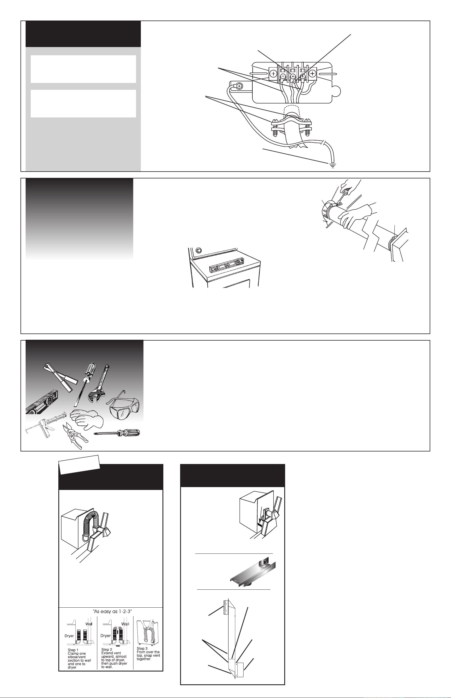
6. Connect the other
wires to outer terminal
block screws. Tighten
screws.
7. Tighten strain
relief screws.
8. Insert tab of terminal block
cover into slot of dryer rear
panel. Secure cover with
hold-down screw.
5. Remove the appliance
ground wire (green with yellow
stripes) from the external
ground connector screw.
Connect appliance ground wire
and the neutral wire (white or
center) of the power supply
cord/cable under the center,
silver-colored terminal block
screw. Tighten screw.
9. Connect a separate copper ground wire
from the external ground connector screw to
an adequate ground.
4. Remove center terminal block screw.
DIRECT WIRE
OR POWER SUPPLY CORD
Where local codes Do Not permit
connecting cabinet-ground conductor to neutral wire:
Three-wire power supply cord must be
four feet long and have three, No.-10
copper wires and match a three-wire
receptacle of NEMA Type 10-30R.
Direct wire power supply cable must be
prepared as shown in “Preparing the wire”
of the three-wire connection direct-wire
steps above.
If codes permit and a separate ground
wire is used, it is recommended that a
qualified electrician determine that the
ground path is adequate.
Panel E
D. Level & exhaust
the dryer
Dryer must be level to reduce noise and assure
proper performance.
Slide dryer onto cardboard or hardboard before
moving across floor to prevent floor damage.
1. Move dryer close to its permanent location.
Leave enough room to connect exhaust vent. Remove
cardboard or hardboard from under dryer.
2. Check levelness of dryer by placing a level on
top of dryer, first side to side, then front to back. If
dryer is not level, adjust dryer legs up or down.
If legs are not long enough to level dryer, order
Extended Dryer Feet Kit, Part No. 279810 (sold two
legs per kit), from your dealer.
3.
Using a 4" clamp,
connect exhaust vent to
exhaust outlet in dryer. If connecting
to existing exhaust vent, make sure
the vent is clean.
The dryer exhaust vent must fit over the dryer
exhaust outlet and inside the exhaust hood.
Make sure exhaust vent is secured to exhaust hood
with a 4" clamp.
4. Move dryer into final position. Do not crush
or kink exhaust vent. Make sure dryer is level.
3. Read the Use and Care Guide to fully
understand your new dryer. Select a full heat cycle
(not the air cycle) and start dryer. After five minutes,
open dryer door. You should feel heat inside dryer.
If dryer does not operate properly, check the
following:
✔ electrical supply is connected.
✔ house fuse is intact and tight; or circuit breaker
has not tripped.
✔ dryer door is closed.
✔ controls are set in a running or “On” position.
✔ start button has been pushed firmly.
If dryer makes an unusual noise, check that the dryer
is level.
E. Check operation
1. Check that you:
✔ did not skip any steps.
✔ installed all parts.
✔ properly installed dryer legs.
✔ leveled dryer.
✔ have secured all exhaust vent joints with 4" clamps.
✔ have all the tools you started with.
2. Plug power supply cord into grounded outlet
or connect direct wire to power supply. Turn power
supply on.
4" clamp
4" clamp
SURE CONNECTTMVent Kit
CRUSH
RESISTANT
Dura Safe
TM
Kits Make Installation Easy
◆Provides 4 1/2”
clearance between
dryer and wall
◆Snap-Lock fittings
◆Total kit length
8 feet
◆Additional vent can
be snapped between
sections for
longer runs
Kit Contains:
2- 4' vent sections with attached close elbows
1- Wall plate for close clearance installations
2- 4" clamps
Part #4396028
Sections separate,
fittings can face
same or opposite
Extra long
band-clamp
for dryer
connection
Swivel collar
Beveled edges
allow corner
installations
Telescoping
sections
Swivel collar
wall connection
◆ Provides 2 1/2” clearance
between dryer and wall
◆ Great for closet
installations
◆ 0"-18", 18”-29” or
29”-50” periscopes
include one male
snap-lock fitting,
one extra long
draw-band collar
and one clamp
2
1
/2"
2 1/2"
Periscopes For Offset
Outlets, Tight Installations
◆ Use when vent outlets
overlap or are offset
◆ Excess length can
be trimmed to fit
18"-29" and 29"-50" Periscope
0"-18" Periscope
0"-18" : Part #4396037
18"-29" : Part #4396011
29"-50" : Part #4396014
Part #4396037
18"-29" : Part #4396011 29"-50" : Part #4396014
Dura Safe and Sure Connect are Trademarks of Whirlpool, U.S.A.
For more information,
or to easily place your
order, call
1-800-442-9991
To have your venting
professionally installed,
call
1-800-253-1301
for the nearest
authorized service
provider.
.
Page 7
✔
Before you start:
Your safety and the safety of others
is very important.
We have provided many important safety messages
in this manual and on your appliance. Always read
and obey all safety messages.
This is the safety alert symbol. This
symbol alerts you to hazards that can kill
or hurt you and others. All safety
messages will be preceded by the safety alert symbol
and the word “DANGER” or “WARNING”. These
words mean:
D ANGER
You will
follow instructions.
be killed or seriously injured if you don’t
WARNING
You can
follow instructions.
All safety messages will identify the hazard, tell
you how to reduce the chance of injury, and tell you
what can happen if the instructions are not
followed.
Check that you have everything necessary for correct
installation. Proper installation is your responsibility.
Tools needed:
be killed or seriously injured if you don’t
Parts supplied:
Remove parts package from
dryer drum. Check that all 4
legs were included.
4 leveling legs
Parts needed:
Check local codes and see electrical and venting
requirements, Panels A and B, before purchasing parts.
Determine if you will need to purchase a power
supply cord kit or power supply cable.
Electrical
If using a power supply cord:
Dryer power supply cord must be:
• U.L.-listed
• 120/240-volt
minimum
The wires that connect to the dryer must end in ring
terminals or spade terminals with upturned ends.
The receptacle must be located within 3 feet of the
top, back center of the control console.
If your outlet
looks like this:
4-wire receptacle
(14-30R)
• 30-ampere
• Type SRD or SRDT
• At least 4 feet long
Choose this
power supply cord:
4-wire power supply cord with
ring or spade terminals and
U.L.-listed strain relief
Venting
WARNING
Fire Hazard
Use a heavy metal vent.
Do not use a plastic vent.
Do not use a metal foil vent.
Failure to follow these instructions can
result in death or fire.
Four-inch heavy metal exhaust vent and clamps
must be used. Dura Safe™ vent products are
recommended.
Dura Safe vent products can be purchased from your
dealer or by calling Whirlpool Parts & Accessories
1-800-442-9991, Mon-Fri: 8am to 9pm (CST), Sat:
9am to 4:30pm (CST). Visit our internet site at
http://www.whirlpoolappliances.com/accessories
See Panel C for more information.
Exhaust hood
Do Not use exhaust hoods with magnetic latches.
Preferred Acceptable
• #2 Phillips screwdriver
• flat-blade screwdriver
• adjustable wrench that
opens to 1" or 1" hexhead socket wrench (for
adjusting dryer feet)
• level
• wire stripper (direct wire
installations)
Part No. 3979171
© 2001 Whirlpool Corporation
• safety glasses
• caulking gun and
• gloves
• tin snips (new vent
compound (new vent
installation)
installations)
3-wire receptacle
(10-30R)
3-wire power supply cord with
ring or spade terminals and
U.L.-listed strain relief
If connecting by direct wire:
Power supply cable must match power supply
(4-wire or 3-wire) and be:
• flexible armored or non-metallic sheathed copper
cable (with ground wire). All current-carrying wires
must be insulated. See Panels D and E.
• 10-GAUGE SOLID COPPER WIRE. (Do not use
aluminum.)
• at least 4 feet long.
Benton Harbor, Michigan 49022
4"
4"
2-1/2"
Mobile home installations require:
• Mobile Home Installation Kit, Part Number 346764*
• Metal exhaust system hardware*
Floors sloped greater than 1 inch:
Require Extended Dryer Feet Kit, Part No. 279810*
Available for purchase from your dealer.
*
Printed in U.S.A.
 Loading...