

Whirlpool 220038-L 010 User Manual
IMPORTANT:
Read and save
these instructions.
I
IMPORTANT
Installer: Leave Installation Instructions
with the appliance.
Homeowner: Keep Installation Instructions
for future reference.
Save Installation Instructions for local
electrical inspector’s use.
I
Part No. 220038-l 010 Rev. l/4372281 Rev. A
40” Electric
Freestanding
Range
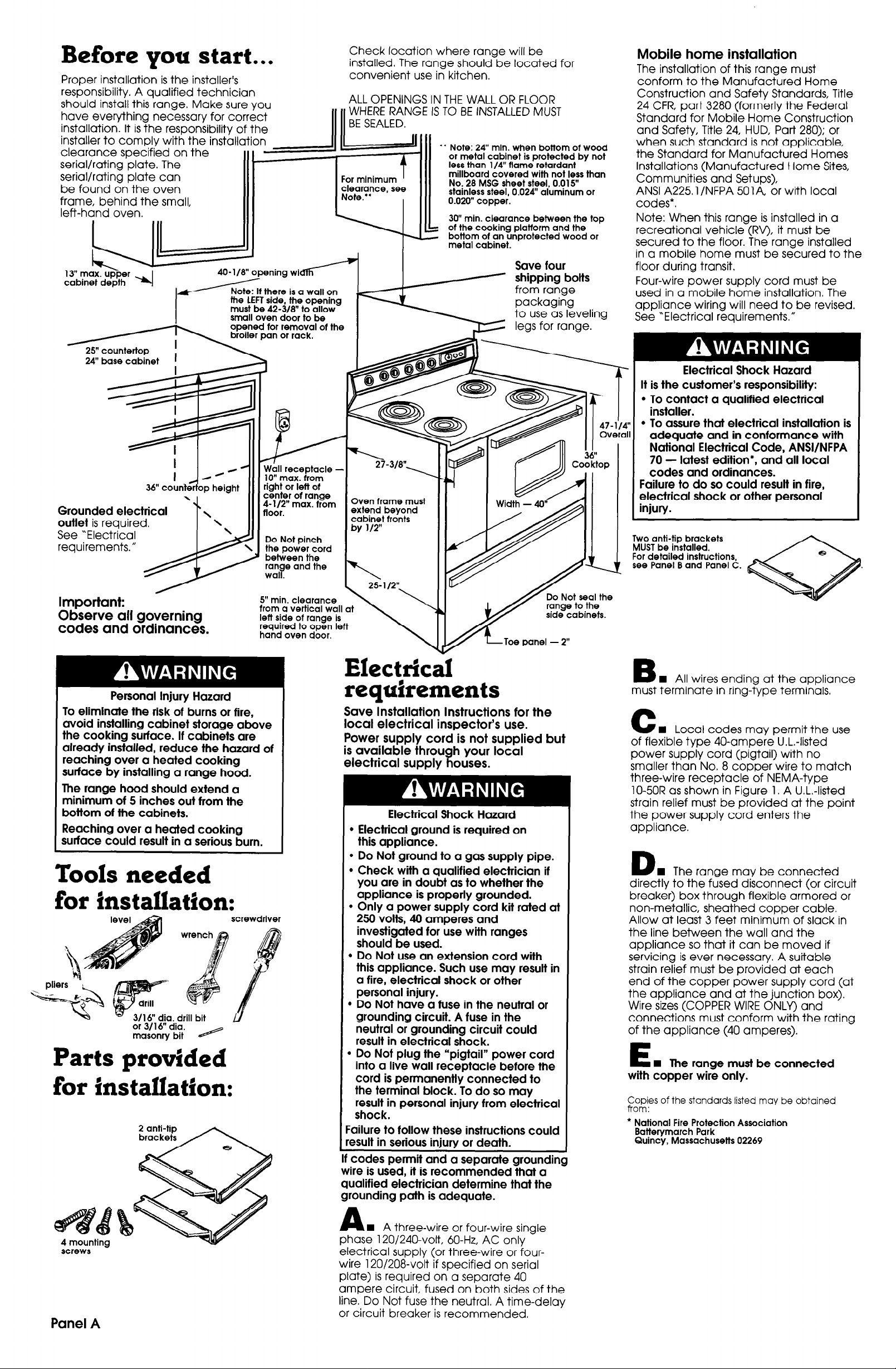
Before you start...
Proper installation is the installer’s
responsibility. A qualified technician
should install this range. Make sure you
have every-thing necessary for correct
installation. It is the responsibility of the
installer to comply with the installation
clearance specified on the
serial/rating plate. The
serial/rating plate can
be found on the oven
frame, behind the small,
left-hand oven.
cabinet depth
-
25” countertop
24” base cabinet
36” counteqop height
Grounded electrical Grounded electrical
outlet is required. outlet is required.
See “Electrical See “Electrical
requirements.” requirements.”
I
I
40-l/8” opening wi
Note: If there is a wall on 1
the LEFT side, the opening
must be 42.3f8” to allow
small oven door to be
opened for removal of the
broiler pan 01 rack.
4
MA/
Wbll receptacle -
lo” max. from
right 01 lett of
center of range
;-l;{T” max. from
Do Not pinch
the power cord
between the
ran B e and the
wal
Check location where range will be
installed. The range should be located for
convenient use in kitchen.
ALL OPENINGS IN THE WALL OR FLOOR
WHERE RANGE IS TO BE INSTALLED MUST
l
* Note: 24” min. when bottom of wood
or metal cabinet is protected by not
less than l/4” flame retardant
millboard covered with not less than
clearance, see
Note.”
I I
Oven frame must
extend beyond
cabinet fronts
by l/2”
No. 28 MSG sheet steel, 0.015”
stainless steel, 0.024” aluminum 01
0.020” copper.
30” min. clearance between the top
of the cooking plafform and the
?
- bottom of an unprotected wood or
metal cabinet.
Mobile home installation
The installation of this range must
conform to the Manufactured Home
Construction and Safety Standards, Title
24 CFR, part 3280 (formerly the Federal
Standard for Mobile Home Construction
and Safety, Title 24, HUD, Part 280); or
when such standard is not applicable,
the Standard for Manufactured Homes
Installations (Manufactured Home Sites,
Communities and Setups),
ANSI A225 1 /NFPA 501 A, or with local
codes*.
Note: When this range is installed in a
recreational vehicle (RV), it must be
secured to the floor. The range installed
in a mobile home must be secured to the
floor during transit.
Four-wire power supply cord must be
used in a mobile home installation. The
appliance wiring will need to be revised.
See “Electrical requirements.”
Electrical Shock Hazard
It is the customer’s responsibility:
l
To contact a qualified electrical
installer.
l
To assure that electrical installation is
adequate and in conformance with
National Electrical Code, ANSI/NFPA
70 - latest edition*, and all local
codes and ordinances.
Failure to do so could result in fire,
electrical shock or other personal
injury.
Two anti-tip brackets
MUST be installed.
For detailed instructions,
see Panel B and Panel C.
Important:
Observe all governing
codes and ordinances.
Personal Injury Hazard
To eliminate the risk of burns or fire,
avoid installing cabinet storage above
the cooking surface. If cabinets are
already installed, reduce the hazard of
reaching over a heated cooking
surface by installing a range hood.
The range hood should extend a
minimum of 5 inches out from the
bottom of the cabinets.
Reaching over a heated cooking
surface could result in a serious burn.
Tools needed
for installation:
screwdriver
for installation:
5” min. clearance
from a vertical wall at
left side of range is
required to open left
hand oven door.
Electrical requirements
Save Installation Instructions for the
local electrical inspector’s use.
Power supply cord is not supplied but
is available throu
electrical supply
If codes permit and a separate grounding
wire is used, it is recommended that a
qualified electrician determine that the
grounding path is adequate.
Do Not seal the
side cabinets.
h your local
a ouses.
Electrical Shock Hazard
l
Electrical ground is required on
this appliance.
l
Do Not ground to a gas supply pipe.
l
Check with a qualified electrician if
you are in doubt as to whether the
appliance is properly grounded.
l
Only a power supply cord kit rated at
250 volts, 40 amperes and
investigated for use with ranges
should be used.
l
Do Not use an extension cord with
this appliance. Such use may result in
a fire, electrical shock or other
personal injury.
n Do Not have a fuse in the neutral or
grounding circuit. A fuse in the
neutral or grounding circuit could
result in electrical shock.
b Do Not plug the “pigtail” power cord
into a live wall receptacle before the
cord is permanently connected to
the terminal block. To do so may
result in personal injury from electrical
shock.
:ailure to follow these instructions could
esult in serious injury or death.
.~
B
n
All wires ending at the appliance
must terminate in ring-type terminals,
C
n
Local codes may permit the use
of flexible type 40-ampere U.L.-listed
power supply cord (pigtail) with no
smaller than No. 8 copper wire to match
three-wire receptacle of NEMA-type
lo-50R as shown in Figure 1. A U.L.-listed
strain relief must be provided at the point
the power supply cord enters the
appliance.
D
n
The range may be connected
directly to the fised disconnect (or circuit
breaker) box through flexible armored or
non-metallic, sheathed copper cable.
Allow at least 3 feet minimum of slack in
the line between the wall and the
appliance so that it can be moved if
servicing is ever necessary A suitable
strain relief must be provided at each
end of the copper power supply cord (at
the appliance and at the junction box).
Wire sizes (COPPER WIRE ONLY) and
connections must conform with the rating
of the appliance (40 amperes).
E
n
lhe range must be connected
with copper wire only.
Copies of the standards listed may be obtained
from:
l
National Fire Protection Association
Batterymarch Park
Quincy, Massachusetts 02269
screws
Panel A
A
n
A three-wire or four-wire sinale
phase 120/240-volt, 60.Hz, AC only ”
electrical supply (or three-wire or four-
wire 120/208-volt if specified on serial
plate) is required on a separate 40
ampere circuit, fused on both sides of the
line. Do Not fuse the neutral. A time-delay
or circuit breaker is recommended.
 Loading...