

Page 1
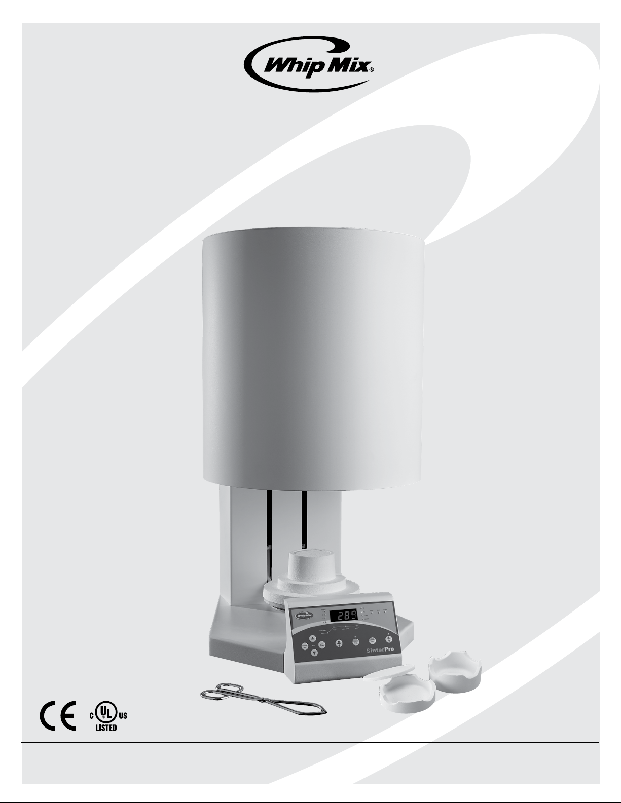
SinterPro
Operator’s Manual
Whip Mix Corporation • 361 Farmington Ave. • P.O. Box 17183 • Louisville, KY 40217-0183 USA
502-637-1451
•
800-626-5651 • Fax 502-634-4512 • www.whipmix.com
Page 2

SinterPro Furnace Operator’s Manual
Table of Contents
Introduction ...........................................................................3
Warranty ................................................................................3
Specifications ........................................................................3
Safety Instructions .................................................4
Unpacking the Furnace
Before Unpacking .................................................................4
Unpacking .............................................................................4
Installing Heating Rods .........................................................6
Lifting and Carrying ...............................................................7
Setting Up The Oven ............................................8
Connecting Power to the Furnace .............8
Back Panel Component
Familiarization
...........................................................8
Controls & Indicator Familiarization
Controls Description .............................................................9
Indicators Description ...........................................................9
To Program And Operate –
Four Stage Program
Running a Program .............................................................15
............................................15
To Review A Program .........................................15
Edit A Program While The
Program Is Running
.............................................16
Purging The Oven .................................................16
Troubleshooting .....................................................17
Routine Maintenance
Cleaning Instructions ..........................................................19
Fan Filter Cleaning (Weekly) ................................................19
Power Failure ...........................................................19
Service ..........................................................................19
Lift Preventative Maintenance ....................20
Powering On The Furnace .............................10
To Set Temperature Scale ...................................................10
To Turn The “Beep” On And Off ..........................................10
Muffle Standby Heat ...........................................10
Lift Operation ...........................................................11
Loading The Sintering Trays .........................11
Cooling Modes Available .................................11
To Program And Operate –
One Stage Program
Sample One Stage Program ...............................................12
Running a Program .............................................................12
.............................................12
To Program And Operate –
Two Stage Program
Sample One Stage Program ...............................................13
Running a Program .............................................................13
.............................................13
Replacement Of Heating Elements .........22
Replacement Of Thermocouple .................23
Replacement Of Logic PCB ...........................24
Replacement Of Alarm PCB ..........................24
Replacement Of Solid State Relay ...........25
Replacement Of Voltage
Monitor PCB
..............................................................26
SinterPro Wiring Diagram ...............................27
Spare Parts List ......................................................28
Service ..........................................................................28
To Program And Operate –
Three Stage Program
Sample One Stage Program ...............................................14
Running a Program .............................................................14
.........................................14
2
Page 3

SinterPro Furnace Operator’s Manual
Introduction
Thank you for purchasing a SinterPro Sintering Furnace.
We have designed and manufactured this furnace using
the latest in microcomputer technology to give you many
years of dependable service. To ensure that your SinterPro
Sintering Furnace gives you the highest level of service,
review and follow the guidelines outlined in this Operator’s
Manual.
Warranty
This Whip Mix equipment is warranted to be free from
defects in material and workmanship from the date of
installation for a period of 2 years on the unit. 1 year on the
muffle*, thermocouple and heating elements.
Any item returned to our factory through an authorized
dealer, will be repaired or replaced at our option at no
charge provided that our inspection shall indicate it to have
been defective. Dealer, labor, shipping and handling charges
are not covered by this warranty.
This warranty does not apply to damage due to shipping,
misuse, careless handling or repairs by other than
Specifications
Electrical Power Requirements:
#96553 16 Amp Model: 208 – 240 VOLT 50/60Hz Single
Phase, 16 Amps, 3680 Watts
#96550 20 Amp Model: 200 – 240 VOLT 50/60 Hz Single
Phase, 20 Amps, 4600 Watts
Overall Dimensions:
17" (43.2 cm) Wide × 25.5" (65cm) Deep ×
33.24" (84.5 cm) High
Heating Chamber Dimensions:
3.5" ( 9 cm) Diameter × 6.5" (16.5 cm) High
authorized service personnel. Whip Mix is not liable for
indirect or consequential damage or loss of any nature in
connection with this equipment.
This warranty is in lieu of all other warranties expressed
or implied. No representative or person is authorized to
assume for us any liability in connection with the sale of our
equipment.
*Attention: Hairline cracks in the muffle insulation, sintering
trays, and firing tray cap are normal, and to be expected.
These components carry a 1 year warranty with the
exception of hairline cracks in these components.
Maximum Heat Rate*: 1 – 54°F/min. (1 – 30°C/min.)
Temperature: Stage 1,2,3,4: 158°F – 2858°F
(70°C – 1570°C*) 1-30˚C/minute*
* Programmable heat rates. Actual heat rate at high
temperatures may be lower depending upon furnace load
and electrical voltage.
Hold Time: 0 – 4 hours on each Stage
Environmental Conditions
• Indoor use
Oven Weight: 132 Lbs. (60.0 kg)
Shipping Weight: 191 Lbs. (86.6 kg)
Maximum Temperature: 1570°C (2858°F)
Number of Programs: 30
Programs 1-2 are pre-programmed with Vericore Zirconia
fast and slow sintering cycles.
Number of Stages/Program: 1 – 4, User defined.
Delay Start: 0 – 8.0 hours
HVAC Load: 15,710 BTU/Hour (20 amp unit)
12,568 BTU/Hour (16 amp unit)
• Altitude up to 2000m
• Environmental Temperature 5°C to 35°C (41°F to 95°F)
• Maximum relative humidity 80% for temperatures up to
31°C (88°F) decreasing linearly to 50% relative humidity
at 35°C (95°F)
• Mains supply voltage fluctuations not to exceed +/– 5%
of the nominal voltage
• Pollution Degree 2, Installation Category II
• Protection Degree IP20 – protected against objects
greater than 12.5mm, no liquid protection
3
Page 4
SinterPro Furnace Operator’s Manual
ATTENTION USERS:
SAFETY INSTRUCTIONS
DO NOT ATTEMPT INTERNAL SERVICE
THIS SYMBOL WARNS THE USER TO USE CAUTION
BECAUSE THE SURFACE IS HOT.
Use of the SinterPro furnace not in conformance with the
instructions specified in this manual may result in premature
failure of the unit.
THIS SYMBOL ALERTS THE USER THAT IMPORTANT
OPERATING AND MAINTENANCE INSTRUCTIONS HAVE
BEEN INCLUDED WITH THE UNIT. READ CAREFULLY TO
AVOID ANY PROBLEMS.
THIS SYMBOL ALERTS THE USER THAT HAZARDOUS
ELECTRICAL VOLTAGES ARE PRESENT.
WARNING: TO PREVENT FIRE OR ELECTRICAL SHOCK, DO NOT
EXPOSE THIS APPLIANCE TO RAIN OR MOISTURE.
Important Note:
The muffle insulation in your SinterPro is likely to
accumulate moisture if the oven is not used regularly. It is
strongly advised that before you put any work product in
the oven for the first time or any time it has been unpowered
for more than a weekend you run the following drying
cycle; a Rate Rise of 10˚C/minute to 500˚C, Hold .5 hours.
This procedure will bake out any retained moisture in the
insulation. If the power is left on the unit will show “IDLE” in
the display and keep the muffle warm.
WARNING: THE INTERIOR OF THE MAIN ASSEMBLY IS ONLY
ACCESSIBLE BY REMOVING HARDWARE WITH TOOLS AND
SHOULD ONLY BE OPENED AND SERVICED BY QUALIFIED
TECHNICIANS. SINCE THE INTERIOR OF THE UNIT MAY CONTAIN
HIGH VOLTAGE AND DANGEROUS COMPONENTS, FAILURE TO
HEED THIS WARNING MAY RESULT IN EQUIPMENT DAMAGE,
PERSONAL INJURY AND/OR DEATH.
CAUTION: THE TEMPERATURE DISPLAYED IS ACCURATE ABOVE
70°C (158°F). NEVER INSERT OR RETRIEVE WORK WITH A BARE
HAND. ALWAYS USE THE SINTERING TRAY PLACEMENT TOOL
TO INSERT OR RETRIEVE SINTERING TRAYS OR BURNS MAY
RESULT.
NOTE: CLEAR, THIN, GLASS “SOAP BUBBLES” WILL APPEAR ON
THE HEATER ELEMENTS. THIS IS ENTIRELY NORMAL AND TO BE
EXPECTED. THEY RESULT FROM THE SILICA IN THE ELEMENTS
REACTING WITH AIR AND ARE CHEMICALLY INERT, AND WILL
NOT REACT CHEMICALLY WITH YOUR WORK PRODUCT. THERE
IS NO NEED TO “CLEAN” THE ELEMENTS. WE RECOMMEND
THE USE OF A LID ON THE TOP OF YOUR SAGGER TRAY STACK
TO PREVENT THE SILICA DEBRIS FROM LANDING INSIDE THE
TOPMOST TRAY.
NOTE: THE USE OF ACID BASED STAINS CAN REACT WITH THE
HEATER ELEMENTS AND SHORTEN THEIR LIFE.
NOTE: DO NOT TURN OFF THE OVEN POWER UNTIL AFTER
THE MUFFLE TEMPERATURE HAS RETURNED TO ROOM
TEMPERATURE TO PREVENT DAMAGE TO ELECTRONICS AS THE
COOLING FANS ARE NEEDED.
Unpacking The Furnace
IMPORTANT: NEVER TIP OR TILT THE FURNACE ONTO
ITS SIDE OR BACK. DOING SO MAY DAMAGE THE
HEATING ELEMENTS OR THE THERMOCOUPLE. SAVE
ALL PACKAGING MATERIALS TO SHIP THE FURNACE
BACK FOR SERVICE IN THE FUTURE SHOULD THERE
BE A NEED.
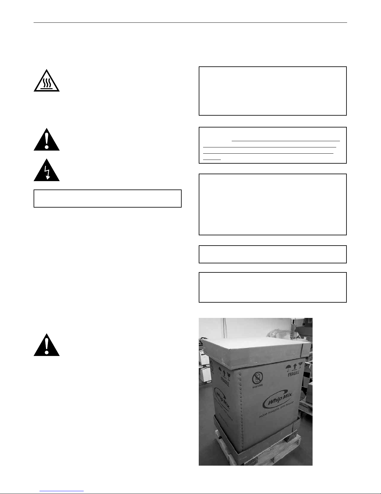
1. Inspect the carton for any signs of shipping damage. If
anything looks suspicious call before unpacking the
unit so that a freight claim inspector can validate.
2. Use a pallet jack to position the oven as near to the site
of use as possible.
3. Remove the bands and shrink wrap securing the carton
to the pallet.
4
Page 5
SinterPro Furnace Operator’s Manual
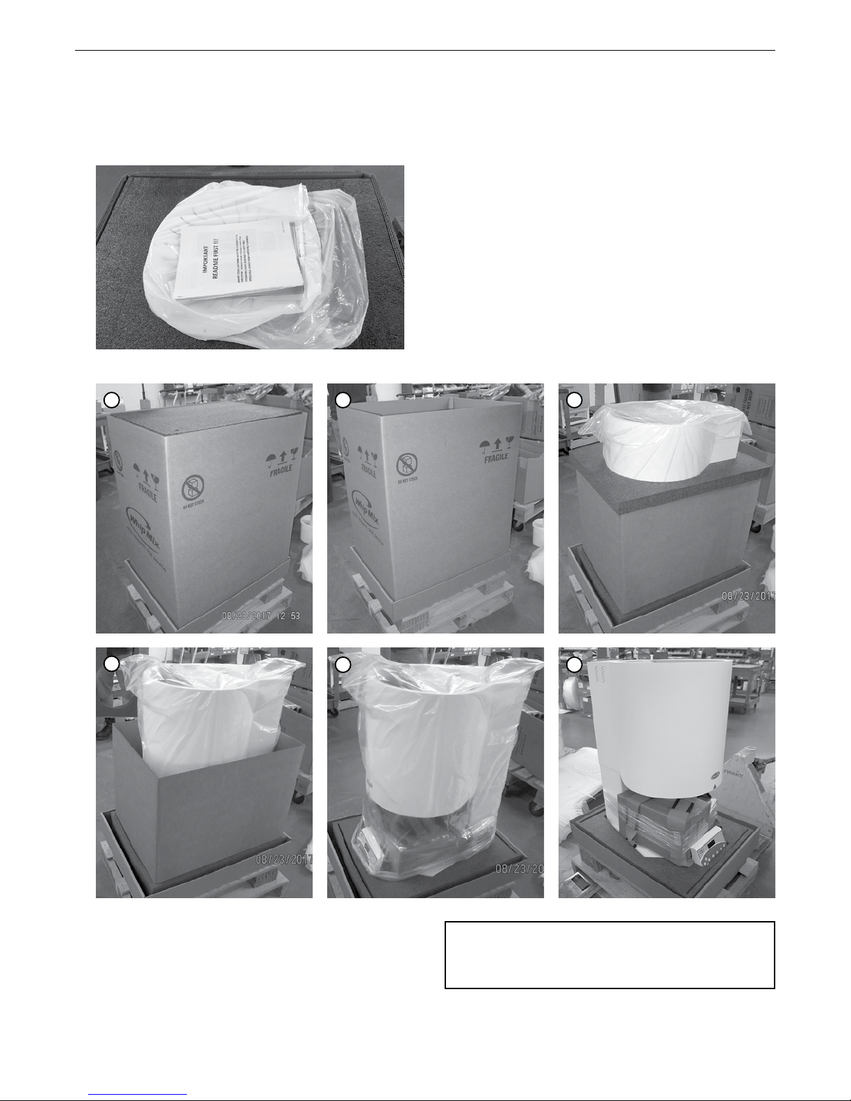
4. Remove carton lid and locate “READ ME FIRST”
document to review important instructions to
familiarize unpacking of SinterPro furnace.
Remove white metal lid and other documents; set aside
until needed.
5. Remove black cut foam spacers, outer carton.
1 2
4
3
5
6
NOTE: DO NOT REMOVE THE OVEN FROM THE SHIPPING SKID
UNTIL INSTRUCTED TO DO SO. THE FOLLOWING STEPS ARE
MUCH EASIER TO PERFORM WHEN THE TOP OF THE MUFFLE IS
AT WAIST HEIGHT WHILE ON THE SHIPPING PALLET.
5
Page 6
SinterPro Furnace Operator’s Manual
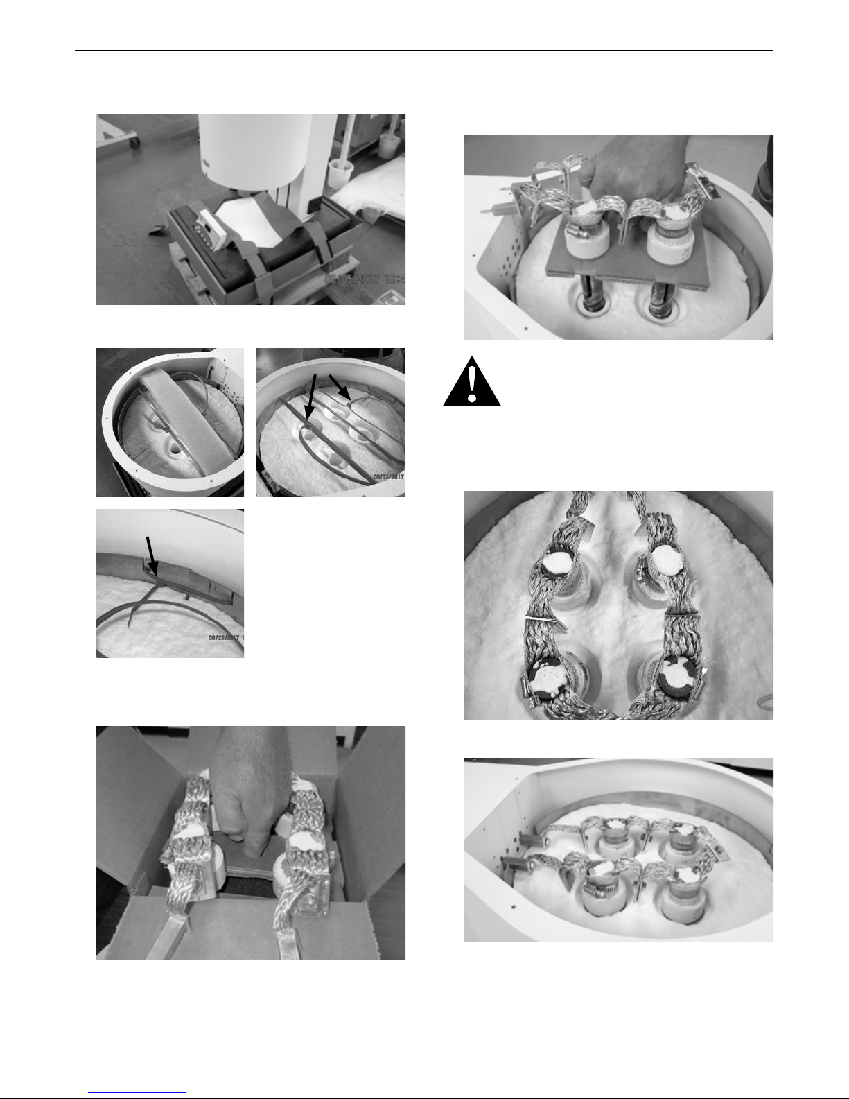
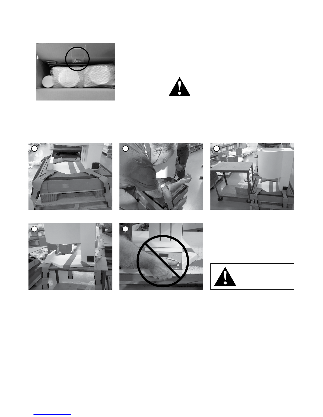
6. Remove both the Accessory box (small) and the Heater
Element box (large) from the unit.
7. Remove foam and wire ties (both long and short).
Remove
9. Lower the heater rods into the wells with the two
electrical plugs oriented towards the rear of the oven.
Carefully remove the cardboard insert from the side.
IMPORTANT! REMOVE THE CARDBOARD CARRIER BY
SLIDING IT SIDEWAYS. YOU MAY HAVE TO GRASP THE
BRAIDED STRAPS AND MOMENTARILY RAISE TWO OF
THE HEATER RODS A COUPLE INCHES TO WITHDRAW
THE CARDBOARD. DO NOT APPLY POWER UNTIL THE
CARDBOARD IS REMOVED!
10. Heating rod insertion after removing the cardboard
insert.
Remove
8. Open the Heater Element box from the end as noted on
the box and remove the 4 heater rods by pulling up the
cardboard insert.
11. Insert the two plugs into the receptacles.
6
Page 7
SinterPro Furnace Operator’s Manual
12. Locate plastic bag containing 8 screws taped to the
inside of the Accessory box lid.
13. Mount white metal perforated lid with 8 screws
provided.
14. Save all packaging/shipping materials in case
FOUR persons required to lift the unit onto work surface. (60kg / 132 lb)
1
2
of return/repair. The Customer is responsible for
re-packaging the furnace like it was received. The
furnace must be returned in original carton to
prevent damage. Failure to retain packaging will incur a
charge for a new carton plus shipping of empty carton.
15. Remove the oven from the shipping pallet following the
procedure pictured below:
CAUTION: THE OVEN WEIGHS 132 LB/60 KG.
LIFTING AND PLACEMENT OF THE OVEN IS A SAFE
PROCEDURE WHEN PERFORMED WITH FOUR (4)
PERSONS. THE PROVIDED LIFT STRAPS (ORANGE)
HAVE 3 LOOPS EACH. USE THE LOOP BEST SUITED
FOR YOUR HEIGHT IN ORDER TO USE YOUR LEGS TO
LIFT (NOT YOUR BACK). PLACE THE LOOP OVER YOUR
FOREARM UP TO THE ELBOW, THEN USE THE SAME
HAND PLACED ON THE OVEN TO STEADY THE LOAD.
3
Fold out straps (4)
4
After placement, tilt oven back to remove
straps and save with the rest of material
Each person (4) place arm through loop
5
Placing the furnace
• Place the SinterPro on a non-flammable, level surface
capable of supporting 200 lb. / 90 kg. The surface
should be high enough to allow easy access to the
muffle cavity for loading and unloading the muffle.
• Leave at least 12 in. / 31cm of unobstructed air
space around all sides and the rear of the furnace for
ventilation.
• Make sure that there is at least 36 in. / 92 cm of free
air space above the top of the SinterPro cabinet for
ventilation.
up to elbow
Place same hand on oven to steady
CAUTION! DO NOT LIFT BY
FRONT PANEL OR DAMAGE
WILL OCCUR!
• The SinterPro Oven should not be placed in such
a way as to obstruct access to the AC Mains
disconnect to the oven in case of an emergency.
7
Page 8
SinterPro Furnace Operator’s Manual
Setting Up The Oven
Unpack contents of the accessory carton.
Contents:
• 1 ea. metal forceps for handling sintering trays
• 1 ea. shallow ceramic sintering tray
• 1 ea. deep ceramic sintering tray
• 1 ea. Sintering ceramic tray lid
• 1 ea. Jar ceramic beads
• Power Cord
• Firing Tray Crown
• Cooling Tray
• USB Flash Drive
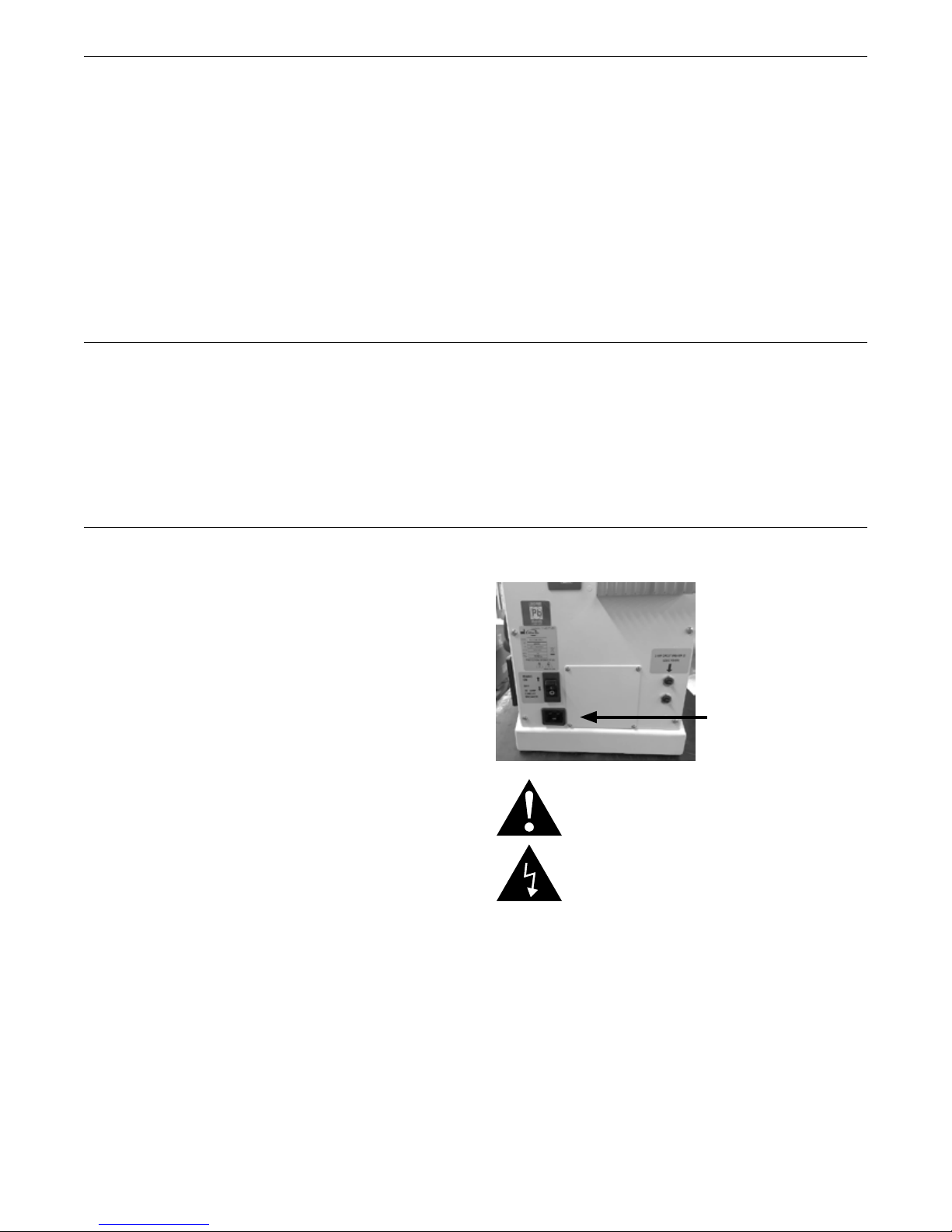
• Locate the Power Cord and plug the appropriate end
into the back of the oven (see picture below), and the
other end into the wall power outlet. Electrical power
requirements include US and CAN: 200/240 VAC, 20 A.
and International: 230 VAC, 16 A.
Connecting Power to the Furnace
A dedicated mains power circuit is required. Make sure
the wall supply wire size accounts for the distance from the
power source to the oven outlet. The maximum impedance
of the power supply to the furnace must be less than
0.032 ohms, as determined by licensed electrician.
Back Panel Component Familiarization
1. Mains Power / Circuit Breaker.
2. 3 AMP Control Logic Circuit Breakers (2).
3. Mains Power Cord.
Power: The On/Off power switch is also a circuit breaker.
The switch will flip to a neutral position when triggered. To
reset the circuit breaker press the switch to the Off position,
then rock it towards the On position. You may have to wait a
minute for the thermal breaker to cool off before it will latch
in the ON position.
NOTE: The (2) 3 AMP circuit breakers must be set (pushed
in) in order to apply power to the Muffle Heaters.
Insert Power Cord
CAUTION:ALWAYS SWITCH OFF THE POWER SWITCH
AND UNPLUG THE POWER CORD BEFORE SERVICING
THE OVEN.
8
Page 9
SinterPro Furnace Operator’s Manual
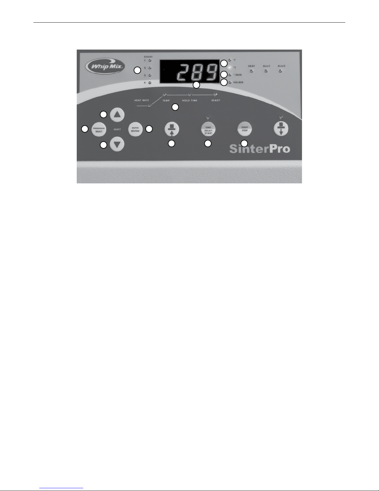
Controls & Indicator Familiarization
8
13
2
1 4
9
10
12
11
3
5 6 7
Controls Description (Left To Right)
1. PROGRAM SELECT: Press to select a program or to
review the program currently running.
2. Press the Up Arrow key to increase a number. The
longer the button is pressed, the faster the numbers
increase.
3. Press the Down Arrow key to decrease a number. The
longer the button is pressed, the faster the numbers
decrease.
4. ENTER / REVIEW: When programming or reviewing
a program in process, press to advance to the next
parameter.
5. Press the Table Up button to raise the lift platform.
6. Press the DELAY START button to delay the start
of a program. The number entered is the time delay
required before the selected Program begins.
7. START / STOP button: Press to immediately start or
stop a program.
NOTE: While a program is running, press delay start to
display the time remaining to complete the program.
Indicators Description
8. STAGE 1–2–3–4 indicator lights: While programming,
the number of active stages are illuminated.
9. °F and °C identifies the temperature scale.
10. °/ MIN identifies the heat rate.
11. HH : MM indicates time. Flashing indicates that a
power failure has occurred. (Press the Start/Stop
button to halt the blinking. HH:MM LED will remain off
unless program is actually in a delay before Start time
period.
12. Main Display
A. The 4 digit display indicates the chamber
temperature.
B. When programming or reviewing, the main display
indicates PROGRAM NUMBER, DELAY START
TIME, HEAT RATE, TEMP and HOLD TIME.
C. Displays special words and error codes.
13. Program Status Graph indicates the status of the
sintering process.
9
Page 10

SinterPro Furnace Operator’s Manual
Powering On The Furnace
• Make sure both 3 Amp button circuit breakers are
fully pressed in.
• At the right rear corner of the chassis is the Power
switch. Depress it fully towards the “1” position to
turn on the power.
• The red numeric digital display should illuminate.
• The green “Heat” LED should light for one second,
followed by the yellow “Alarm 1” LED, followed by
the red “Alarm 2” LED. An audible “click” should be
heard one second later; this is the muffle power safety
contactor energizing. If the lift is in the full up position the
display should stop on the word “IDLE”, and the green
“Heat” LED should be flickering.
IMPORTANT: YOU SHOULD HEAR THE COOLING FANS
RUNNING WHENEVER THE OVEN IS POWERED ON.
IF YOU DO NOT HEAR THE FAN (LOCATED UNDER
THE BLACK PLASTIC GRILL AT THE RIGHT LOWER
SIDE OF THE CHASSIS), CALL FOR SERVICE. DO NOT
OPERATE THE OVEN UNLESS THE FAN IS RUNNING.
THE FAN FILTER SHOULD BE CLEANED WEEKLY (SEE
MAINTENANCE SECTION). THE COMPUTER MONITORS
THE FAN SPEED AND WILL GENERATE ERROR 10
FOR A SLOW FAN, AND ERROR 11 FOR A STALLED OR
INOPERATIVE FAN.
• Press the Down Arrow button to lower the lift. Note
the indentation in the top surface of the firing platform.
This indentation is to assist you in centering the sintering
trays.
NOTE: If the Furnace is not running a program, the stage
LED(s) on the left side of the temperature display will be
lit all the time, when a program is running the current
Stage LED will be BLINKING. To end a program, press
the START/STOP button once.
To Set Temperature Scale
The furnace is pre-set in degrees Celsius.
1. Turn the power switch on. If the furnace is already on,
be sure it is in the idle mode – (no program is running).
The chamber temperature appears on the Main Display
and the °C light goes on.
2. To change temperature scale: Press Up Arrow
button and Down Arrow button at the same time. The
degree light switches to the opposite temperature scale
and the displayed value switches to those units.
To Turn The “Beep” On And Off
When a program is completed, 20 “beeps” sound every 15
minutes to inform the operator that the Sintering cycle is
completed.
1. Be sure the oven is in the Standby MODE – (no
program us running).
2. Press the Up Arrow key and PROGRAM SELECT
simultaneously to display the status of the “beep.”
“ON” indicates the beep is active. “OFF” indicates the
beep is inactive.
3. Use either of the Up Arrow or Down Arrow keys to
turn the “beeps” on or off.
4. To return to the Standby mode, wait 7 seconds or
press STOP / START twice. (If STOP / START is
pressed once, the current PROGRAM cycle starts.)
Muffle Standby Heat
The muffle insulation will readily take on moisture from the
air unless the muffle temperature is elevated above room
temperature. This moisture will rapidly turn to steam and
expand quickly enough to crack the insulation - unless
some standby heat is applied whenever a firing program is
not running.
When the oven is not in use, always remove all firing trays
and press the up arrow button to raise the lift platform to the
top. When the lift platform reaches the top position (and the
muffle temperature is below 70°C) the front panel display
will read “IDLE”. Whenever you see the word “IDLE” a small
amount of heat (27 Watts) is being applied to keep the
muffle at or in the vicinity of 48°C (120°F). The green heater
LED will blink to indicate Idle heating.
If the furnace has been sitting in Standby with no user
interaction for an hour, the platform will automatically
close by itself, and apply the IDLE power to the heaters.
If the furnace power has been turned off on a weekend it
is important to allow the furnace muffle be warmed up in
the IDLE Mode with the platform up for at least a couple of
hours to bake out any moisture before running a sintering
program. Rate Rise of 10˚C/minute to 500˚C, Hold .5 hours.
If the lift platform is not fully up, and the muffle is cooler
than 70°C, the display will read “LO”, and no power will be
applied to the heaters.
10
Page 11
SinterPro Furnace Operator’s Manual
Lift Operation
The lift platform may be operated manually when there is no
program running.
To raise the lift platform, depress the button with the symbol
which looks like the sintering tray and has an upward
pointing arrow. To lower the lift platform, depress the button
with the symbol which looks like the sintering tray and has a
downward pointing arrow.
IMPORTANT: IF THE MUFFLE TEMPERATURE IS
ABOVE 300°C, THE RED LED ABOVE THE TABLE DOWN
BUTTON AT THE FAR RIGHT WILL BE LIT, INDICATING
THAT IT IS NOT SAFE TO LOWER THE LIFT PLATFORM.
AS SOON AS THE MUFFLE COOLS BELOW 300°C,
THE LED LIGHT WILL GO OUT AND THE TABLE DOWN
BUTTON IS ENABLED TO LOWER THE LIFT.
Loading The Sintering Trays
Press the Down Arrow button to lower the lift firing platform.
One shallow sintering tray, one deep sintering tray, one lid,
and a zirconia tray liner bead sample jar are included with
your SinterPro oven. The sintering tray is indented at the
bottom to allow the tray to index into the firing tray to hold
the sintering tray concentric with the firing tray.
THE DISPLAY WILL READ “IDLE” (PRE-HEAT) UNTIL
THE PLATFORM LEAVES THE UPPERMOST POSITION,
THEN WILL CHANGE TO “LO”. THE EXCEPTIONS ARE
IF THE FAST COOL “FCL” OPTION OR THE CONTROL
COOL “CCL” OPTION IS SELECTED ON A GIVEN FIRING
CYCLE. IN THESE CASES, THE LIFT WILL END UP IN
THE BOTTOM MOST POSITION WHEN THE CYCLE
IS COMPLETE AND THE GREEN READY LED WILL
INDICATE A NORMAL COMPLETION.
THE LIFT WILL AUTOMATICALLY RISE TO THE FULL UP
POSITION IF THERE HAS BEEN NO KEY PRESSED FOR
ONE HOUR TO PREVENT MOISTURE BUILDUP IN THE
MUFFLE.
IF THE LIFT IS DOWN AND THE START/STOP BUTTON
IS PRESSED THE LIFT WILL GO UP AND THE PROGRAM
WILL COMMENCE.
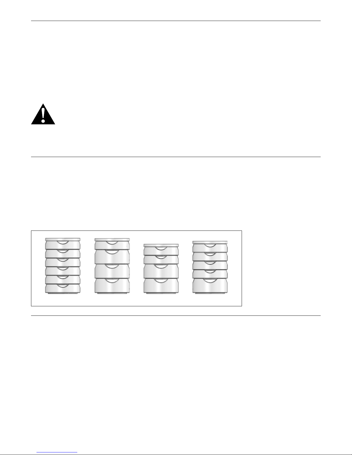
The maximum sintering tray capacity should not exceed
5.6" tall. Below are four legitimate combinations of Whip
Mix shallow and deep trays. If you use any other brand
of trays, the diameter of the tray cannot exceed 90mm
(3.5") and the stack cannot exceed 142mm (5.6") or
damage to the lift or muffle insulation will result.
Cooling Modes Available (3)
There are three cooling modes available with the SinterPro
oven.
1. Fast Cool
2. Controlled Cool
3. Natural Cool
Fast Cool
If you desire to recover your work product in an hour from
maximum temperature, you can select the Fast Cool cooling
mode by arrowing to “FCL” and the lift table will descend
slowly, maintaining a 22˚C per minute cooling rate.
Controlled Cool
If you desire to recover your work product in 2.5 hours
from maximum temperature, you can select the Controlled
Cool cooling mode by arrowing to “CCL” and the lift table
will remain closed until the cooling rate of the muffle drops
below 10˚C/minute, then descend slowly.
Natural Cool (Select “NO”)
The table remains closed throughout the natural cooling
time of approximately 5 hours and 15 minutes from
maximum temperature.
11
Page 12

SinterPro Furnace Operator’s Manual
To Program And Operate – One Stage Program
Note: Always use the START/STOP button to halt a
running program before turning the oven power off.
If you turn the oven off without stopping the program
in progress the power-fail memory feature will
automatically restart the program at the point where the
power either failed or the oven was turned off.
P1 and P2 have been pre-programmed with the sintering
parameters for Vericore Zirconia ZR HT, ZR HTX and ZR Pro.
P1 = a Fast Sinter Cycle and P2 = a Slow Sinter Cycle. The
specific parameters are as follows.
P1: Fast Sinter Cycle
Stage 1: 10°C/min. to 1000°C; No Hold
Stage 2: 5°C/min. to 1500°C; Hold for 2 hours
Stage 3: Fast Cool
P2: Slow Sintering Cycle
Stage 1: 6°C/min. to 900°C; No Hold
Stage 2: 3°C/min. to 1500°C: Hold for 2 hours
Stage 3: Controlled Cool
1. Turn the power switch on.
2. Press PROGRAM SELECT. Use to display the desired
program number (P1 – P30).
3. Press ENTER / REVIEW to display the selected
program. STAGE 1 and DELAYED (START) lights turn
on. If DELAY mode is desired, use the arrow keys to
set the delay time before the program starts (only if
the Delay button is pressed instead of the normal Start
button).
4. Press ENTER / REVIEW. STAGE 1 light remains on,
DELAY (START) light turns off and HEAT RATE light
turns on. Use the arrow keys to scroll for the heat rate
required from 1°F – 54°F/min (1°C – 30°C/min).
5. Press ENTER / REVIEW. STAGE 1 light remains on,
HEAT RATE light turns off and TEMP light turns on.
Use the arrow keys to scroll to select the temperature
required up to the maximum of 1570°C / 2858°F.
6. Press ENTER / REVIEW. STAGE 1 light remains on,
TEMP light turns off and HOLD TIME light turns on.
Use the arrow keys to scroll to the time needed to hold
at above temperature (0 – 4hrs.).
7. To use a one stage sintering cycle, the furnace must
be programmed not to use STAGE 2, 3 or 4. Follow
these steps:
A. After completing step 6 above, press ENTER /
REVIEW. STAGE 1 light turns off, STAGE 2 and
HEAT RATE lights turn on.
B. Press either Arrow key, Main Display shows “.....5,
4, 3, 2, 1, COOL, NO.” Select “NO” to program
the furnace for a one-stage cycle. (NO = Natural
Cooling)
C. If Fast Cooling is desired, scroll to “FCL” or if
Controlled Cooling is desired, scroll to “CCL”
instead of “NO”. This will allow natural cooling
down to around 900°C, then progressively lower the
lift platform automatically to allow cooling air into
the muffle at approximately 15°-20°C/minute rate.
Your work will be retrievable sooner. (FCL or CCL
can only be the last stage of a program, so the
NO entry is not required in this case).
CAUTION: THE TABLE WILL AUTOMATICALLY LOWER
VERY SLOWLY. BE ADVISED THAT THE MATERIAL
TRAYS AND THE LIFT PLATFORM INSULATION ARE
TOO HOT TO SAFELY TOUCH WITH YOUR HAND. USE
FORCEPS AND INSULATED GLOVES WHEN HANDLING
THE SINTERING TRAYS.
8. All necessary information for this program is now
entered.
9. To run the program immediately, press START / STOP.
10. To delay the start of the program press the DELAY
START key.
NOTE: If DELAY START key is pressed while a program
is running, the time remaining for completion of the
program will appear on the Main Display for 5 seconds.
NOTE: It is recommended to wait for muffle to cool
below 300˚C / 572˚F before initiating a new firing cycle to
avoid thermal shock to your work.
Sample One Stage Program
(with delayed start)
Delay Start Heat Rate Temp Hold Time
Stage 1 3:00 30°C
(54°F)
Stage 2 NO (n/a) (n/a)
Stage 3 NO (n/a) (n/a)
Stage 4 NO (n/a) (n/a)
1530°C
(2786°F)
1:00
NOTE: To turn off STAGE 2, 3 and 4, select “NO” for the
HEAT RATE in STAGE 2.
Running A Program
NOTE: Press the START/STOP button to initiate the
program. If the Lift platform is in the down position pressing
the Start/Stop button will cause it to begin rising to the
closed position. Make sure your sintering trays are in
position in the center of the firing platform before initiating
the firing cycle.
NOTE: At the end of the firing cycle the appropriate number
of Stage LEDs will be ON, and the Green “Ready” LED will
be lit to signify the firing cycle is complete. Technically the
firing cycle is still active until you press the START/STOP
12
Page 13

SinterPro Furnace Operator’s Manual
button to extinguish the Ready LED and halt the periodic
beeping. This is useful if you have an overnight run so that
you have confirmation that the cycle completed normally,
even if it is hours later.
To Program And Operate – Two Stage Program
1. Follow One Stage Program, Steps 1 – 6.
2. Press ENTER / REVIEW. STAGE 1 light turns off,
STAGE 2 and HEAT RATE lights turn on. Main Display
shows three heat rate choices. Choose one:
A. Select heat rate between 1°F – 54˚F / min
(1°C – 30°C / min).
B. Select “FCL” or “CCL” to program the cooling
mode.
C. Select “NO” to turn off STAGE 2, 3 and 4. This will
result in a One Stage program.
NOTE: The HEAT RATE cannot be programmed to “COOL”
in STAGE 1 – only in STAGE 2, 3 or 4.
3. Press ENTER / REVIEW. HEAT RATE light turns off
and TEMP light turns on. Use the arrow keys to scroll
for the temperature required: heating temperature up
to a max. of 2858°F (1570°C) or cooling temperature
down to a minimum of 137°F (58°C).
4. Press ENTER / REVIEW. TEMP light turns off and
HOLD TIME light turns on. Use the arrow keys
to program the time needed to hold at the above
temperature (0 – 4hrs.).
5. For two stages, the furnace must be programmed not
to use STAGE 3 or 4. Follow these steps:
A. After completing Step 4, press ENTER / REVIEW.
STAGE 2 light turns off, STAGE 3 and HEAT RATE
lights turn on.
B. Press either Arrow key, Main Display shows
“....5,4,3,2,1, FCL, CCL, NO.” Select “NO” to
program the furnace not to use STAGE 3 or 4.
(Natural Cooling).
C. If Fast Cooling is desired, scroll to “FCL” or if
Controlled Cooling is desired, scroll to “CCL”
instead of “NO”. This will allow natural cooling
down to around 900°C, then progressively lower
the lift platform automatically to allow cooling air
into the muffle at approximately 15°-20°C/minute
rate. Your work will be retrievable sooner. (FCL or
CCL can only be the last stage of a program, so the
NO entry is not required in this case).
CAUTION: THE TABLE WILL AUTOMATICALLY LOWER
VERY SLOWLY. BE ADVISED THAT THE MATERIAL
TRAYS AND THE LIFT PLATFORM INSULATION ARE
TOO HOT TO SAFELY TOUCH WITH YOUR HAND. USE
FORCEPS AND INSULATED GLOVES WHEN HANDLING
THE SINTERING TRAYS.
6. All necessary information for this program is now
entered.
7. To run the program immediately, press START / STOP.
8. To delay the start of the program (see One Stage
Program, Step 3), press DELAY START.
NOTE: If DELAY (START) is pressed while a program
is running, the time remaining for completion of the
program will appear on the Main Display for 5 seconds.
NOTE: It is recommended to wait for muffle to cool
below 300˚C / 572˚F before initiating a new firing cycle
to avoid thermal shock to your work.
Sample Two Stage Program
(to start immediately)
Heat Rate Temp Hold Time
Stage 1 30°C (54°F) 1000°C (1832°F) :10
Stage 2 5°C (9°F) 1500°C (2732°F) 1:00
Stage 3 NO (n/a) (n/a)
Stage 4 NO (n/a) (n/a)
Though any number may appear, the unit is deactivated
when “NO” is selected for the HEAT RATE.
NOTE: To turn off STAGE 3 & 4, select “NO” for the HEAT
RATE in STAGE 3.
To start immediately, press START / STOP.
Follow the same programming procedures if a three or four
stage program is desired.
Running A Program
NOTE: Press the START/STOP button to initiate the
program. If the Lift platform is in the down position pressing
the Start/Stop button will cause it to begin rising to the
closed position. Make sure your sintering trays are in
position in the center of the firing platform before initiating
the firing cycle.
NOTE: At the end of the firing cycle the appropriate number
of Stage LEDs will be ON, and the Green “Ready” LED will
be lit to signify the firing cycle is complete. Technically the
firing cycle is still active until you press the Start/Stop
button to extinguish the Ready LED and halt the periodic
beeping. This is useful if you have an overnight run so that
you have confirmation that the cycle completed normally,
even if it is hours later.
13
Page 14
SinterPro Furnace Operator’s Manual
To Program And Operate – Three Stage Program
1. Follow Two Stage Program, Steps 1 – 4.
2. Press ENTER / REVIEW. STAGE 2 light turns off,
STAGE 3 and HEAT RATE lights turn on. Main Display
shows three heat rate choices. Choose one:
A. Select heat rate between 1°F – 54˚F / min
(1°C – 30°C / min).
B. Select “FCL” or “CCL” to program the cooling
mode.
C. Select “NO” to turn off STAGE 3 and 4. This will
result in a Two Stage program.
NOTE: The HEAT RATE cannot be programmed to
“COOL” in STAGE 1 – only in STAGE 2, 3 or 4.
3. Press ENTER / REVIEW. HEAT RATE light turns off
and TEMP light turns on. Use the arrow keys to scroll
for the temperature required: heating temperature up to
a max. of 1570°C / 2858°F or cooling temperature down
to a minimum of 137°F (58°C).
4. Press ENTER / REVIEW. TEMP light turns off and
HOLD TIME light turns on. Use the arrow keys
to program the time needed to hold at the above
temperature (0 – 4hrs.).
5. For three stages, the furnace must be programmed not
to use STAGE 4. Follow these steps:
A. After completing Step 4, press ENTER / REVIEW.
STAGE 3 light turns off, STAGE 4 and HEAT RATE
lights turn on.
B. Press either Arrow key, Main Display shows “....5,
4, 3, 2, 1, COOL, NO.” Select “NO” to program
the furnace not to use STAGE 3 or 4.
C. If Fast Cooling is desired, scroll to “FCL” or if
Controlled Cooling is desired, scroll to “CCL”
instead of “NO”. This will allow natural cooling
down to around 900°C, then progressively lower
the lift platform automatically to allow cooling air
into the muffle at approximately 15°-20°C/minute
rate. Your work will be retrievable sooner. (FCL or
CCL can only be the last stage of a program, so the
NO entry is not required in this case).
CAUTION: THE TABLE WILL AUTOMATICALLY LOWER
VERY SLOWLY. BE ADVISED THAT THE MATERIAL
TRAYS AND THE LIFT PLATFORM INSULATION ARE
TOO HOT TO SAFELY TOUCH WITH YOUR HAND. USE
FORCEPS AND INSULATED GLOVES WHEN HANDLING
THE SINTERING TRAYS.
6. All necessary information for this program is now
entered.
7. To run the program immediately, press START / STOP.
8. To delay the start of the program (see One Stage
Program, Step 3), press DELAY START.
NOTE: If DELAY START key is pressed while a program
is running, the time remaining for completion of the
program will appear on the Main Display for 5 seconds.
NOTE: It is recommended to wait for muffle to cool
below 300˚C / 572˚F before initiating a new firing cycle
to avoid thermal shock to your work.
Sample Three Stage Program
(program with cooling)
Heat Rate Temp Hold Time
Stage 1 30°C (54˚F) 1000°C (1832°F) :10
Stage 2 10°C (18°F) 1530°C (2786°F) 2:00
Stage 3 5°C (9°F)* 250°C (482°F) (n/a)
Stage 4 NO (n/a) (n/a)
To start immediately, press START / STOP.
Follow the same programming procedures if a three or four
stage program is desired.
NOTE: When the temperature is set to a lower temperature
than in the previous stage, the furnace ignores the
programmed HEAT RATE (except for “NO”) and
automatically cools to the pre-set temperature. The time
required for the cooling stage is determined by the pre-set
temperature. The lower the temperature, the more time
needed to cool down.
NOTE: Press DELAY button to start after a pre-set delay
time elapses. (See SAMPLE ONE STAGE PROGRAM to
program DELAY START time.
Running A Program
NOTE: Press the START/STOP button to initiate the
program. If the Lift platform is in the down position pressing
the Start/Stop button will cause it to begin rising to the
closed position. Make sure your sintering trays are in
position in the center of the firing platform before initiating
the firing cycle.
NOTE: At the end of the firing cycle the appropriate number
of Stage LEDs will be ON, and the Green “Ready” LED will
be lit to signify the firing cycle is complete. Technically the
firing cycle is still active until you press the Start/Stop
button to extinguish the Ready LED and halt the periodic
beeping. This is useful if you have an overnight run so that
you have confirmation that the cycle completed normally,
even if it is hours later.
14
Page 15

SinterPro Furnace Operator’s Manual
To Program And Operate – Four Stage Program
1. Follow Three Stage Program, Steps 1 – 4.
2. Press ENTER / REVIEW. STAGE 3 light turns off,
STAGE 4 and HEAT RATE lights turn on. Main Display
shows three heat rate choices. Choose one:
A. Select heat rate between 1°F – 54˚F/min
(1°C – 30°C/min).
B. Select “FCL” or “CCL” to program the cooling
mode.
C. Select “NO” to turn off Stage 4. This will result in a
Three Stage Program.
NOTE: The HEAT RATE cannot be programmed to
“COOL” in STAGE 1 – (only in STAGE 2, 3 or 4).
3. Press ENTER / REVIEW. HEAT RATE light turns off
and TEMP light turns on. Use the arrow keys to scroll
to the temperature required: heating temperature up
to a max. of 2858°F (1570°C) or cooling temperature
down to a minimum of 137°F (58°C).
4. Press ENTER / REVIEW. TEMP light turns off and
HOLD TIME light turns on. Use the arrow keys to scroll
to the time needed to hold at the above temperature
(0 – 4 hrs.).
5. All necessary information for this program is now
entered.
6. To run the program immediately, press START / STOP.
7. To delay the start of the program to be ready to cast
at the pre–set time (see One Stage Program, Step 3),
press TIME SET (DELAY START).
NOTE: If DELAY (START) is pressed while a program
is running, the time remaining for completion of the
program will appear on the Main Display for 5 seconds.
NOTE: It is recommended to wait for muffle to cool
below 300˚C / 572˚F before initiating a new firing cycle
to avoid thermal shock to your work.
NOTE: If all 4 stages are used to control temp., there are
no remaining Stages left to use the FCL (Fast Cool) feature.
There is no need for a “NO” to signal the end of the cycle.
Running A Program
NOTE: Press the START/STOP button to initiate the
program. If the Lift platform is in the down position pressing
the Start/Stop button will cause it to begin rising to the
closed position. Make sure your sintering trays are in
position in the center of the firing platform before initiating
the firing cycle.
NOTE: At the end of the firing cycle the appropriate number
of Stage LEDs will be ON, and the Green “Ready” LED will
be lit to signify the firing cycle is complete. Technically the
firing cycle is still active until you press the Start/Stop
button to extinguish the Ready LED and halt the periodic
beeping. This is useful if you have an overnight run so that
you have confirmation that the cycle completed normally,
even if it is hours later.
To Review A Program
1. Turn the power switch on.
2. Press PROGRAM SELECT.
3. Use arrow keys to select the program number to be
reviewed. The program number (P1 – P30) will appear
on the Main Display.
4. The number of stages in the program are indicated by
the STAGE lights.
5. Press ENTER / REVIEW.
The DELAY (START) light turns on. The number of
hours/seconds until the Program Starts appears on the
Main Display. After 7 seconds, the DELAY START light
turns off and the actual furnace temperature appears
on the Main Display.
NOTE: STAGE 1 light is now on.
6. Press ENTER / REVIEW and TEMP light turns on. The
programmed temperature (TEMP) for STAGE 1 appears
on the Main Display.
7. Press ENTER / REVIEW and HOLD TIME light turns
on. The programmed HOLD TIME for STAGE 1appears
on the Main Display in HR:MIN.
8. All of the information in STAGE 1 has now been
entered. If ENTER / REVIEW is pressed again,
STAGE2 light turns on. Review STAGE 2 following
the same procedure as above. Continue pressing
ENTER/REVIEW to review all of the individual
parameters in STAGE 2, 3, or 4.
NOTE: DELAY (START) appears only at the very
beginning of STAGE 1.
15
Page 16

SinterPro Furnace Operator’s Manual
Edit A Program While The Program Is Running
1. To identify which program is running, press PROGRAM
SELECT.
NOTE: The program number cannot be changed while the
program is running.
2. To determine the time remaining for the completion of
the program, press the DELAY START button. The time
remaining appears on the Main Display for 5 seconds.
3. Any parameter can be increased or decreased during
the running of any programs.
NOTE: HEAT RATE cannot be changed to “NO” in
the stage currently running or in the stages already
completed.
4. To change a parameter while a program is running,
press ENTER / REVIEW to advance to the desired
Purging The Oven
The recommended program to purge the oven of impurities is:
Stage 1: 20°C per minute to 1550°C with a 1 hour Hold Time.
Stage 2: “NO”
STAGE and parameter (i.e. HEAT RATE, TEMP or HOLD
TIME). Initially, STAGE 1 will appear. Any parameter can
be increased or decreased by pressing the UP ARROW
button or the DOWN ARROW button.
5. Any program can be stopped or started by pressing the
START / STOP button.
6. If a program is edited while running and the HEAT
RATE in STAGE 2, 3 or 4 is set to “COOL” but the
corresponding TEMP programmed is entered to heat
to a higher temperature than the previous stage, the
SinterPro will try to heat with a 0°F / Min (0°C / Min)
HEAT RATE. In this case, when DELAY START button
is pressed, 99:99 (Hr:Min) flashes on the Main Display,
indicating that the program cannot be completed.
16
Page 17
SinterPro Furnace Operator’s Manual
Troubleshooting
Internal Fuse List:
1. Inline Fuses (2) on DC power supply output are:
Bel Fuse, Inc. Part NO. 5ST-4-R, Glass 4Amp, 250
Volt, 5 x 20 mm.
IMPORTANT: YOU SHOULD HEAR THE COOLING FAN
RUNNING WHENEVER THE OVEN IS POWERED ON.
IF YOU DO NOT HEAR THE FAN (LOCATED BELOW
THE MUFFLE HOUSING) CALL FOR SERVICE. DO NOT
OPERATE THE OVEN UNLESS THE FAN IS RUNNING.
2. Voltage Monitor PCB fuses (2) are:
Bel Fuse, Inc. Part NO. 5ST-125-R, Fuse, Glass
125mA, 250VAC 5x20mm
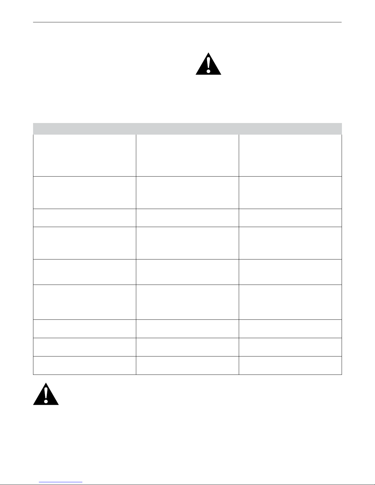
Problem Check Try
Green Heater LED does not come on
and blink every second when program
launched.
If the Green Heater LED does not come
on during the power on self-test call for
service.
Yellow Alarm 1 LED lit constantly Verify that the yellow Alarm 1 does not
remain lit constantly after the power on
self-test is completed. If it does, call for
service.
Red Alarm 2 LED lit constantly If the Alarm 2 comes on again and
stays on, call for service.
Turn oven power switch off, then on
again.
If the 16 amp Mains Power circuit
breaker is tripped reset it. If it trips
again, call for service.
Turn oven power switch off, then on
again.
Turn oven power switch off, then on
again.
Red Alarm 2 LED BLINKING
(This occurs ANYTIME an Er 7 code is
displayed on the temperature display.
See Er_ codes table below.)
No Numeric Display when power
turned on.
No Numeric Display and no other LEDs
lit when power turned on.
Main Circuit Breaker Trips when
program running
Hood Temperature uncomfortably hot
to the touch.
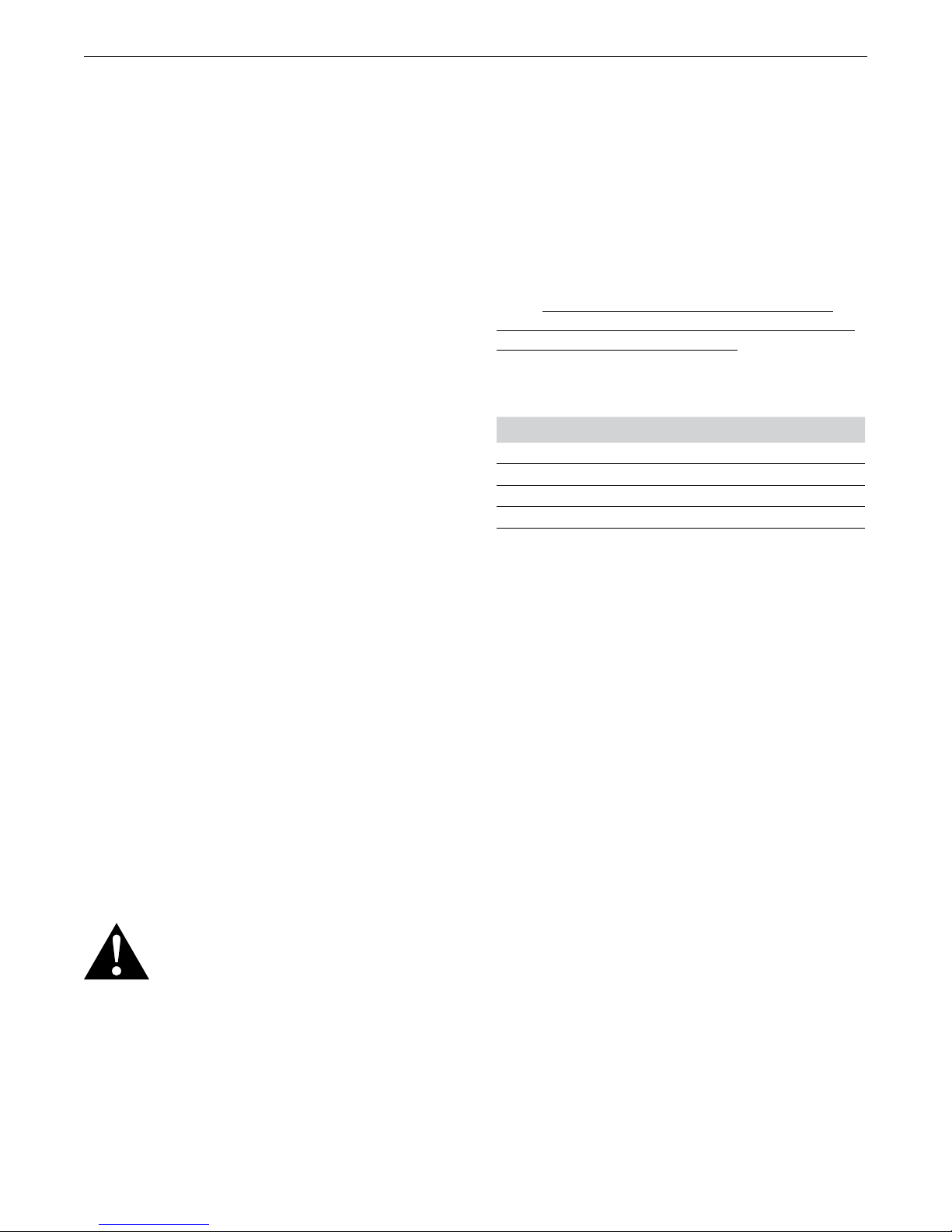
“ER-X” Codes display in the digital
numeric display.
NOTE: ANY TIME ER2 – ER9, & E11 CODES ARE DISPLAYED THE RED ALARM 2 LED SHOULD
BE BLINKING SIGNIFYING THE MUFFLE POWER CONTACTOR HAS REMOVED THE POWER TO
THE HEATERS. THE HEATER POWER WILL NOT BE RESTORED UNTIL THE ROOT CAUSE OF
THE ER_ CODE HAS BEEN RESOLVED AND THE MAINS POWER CYCLED OFF, THEN ON AGAIN.
If the Heater, Alarm 1 & Alarm 2 LEDs
do not come on, then go off, call for
Turn oven power switch off, then on
again.
service.
Button circuit breakers on back panel
are pushed in.
Turn oven power switch off, then on
again.
Check the building power source for
tripped circuit breaker.
Fan filter clogged, fan not running. (fan
Clean fan filter & insure fan running.
in base of column)
Upper fans (2) one or both not turning Call for service.
Refer to the Error Code list below.
17
Page 18
SinterPro Furnace Operator’s Manual
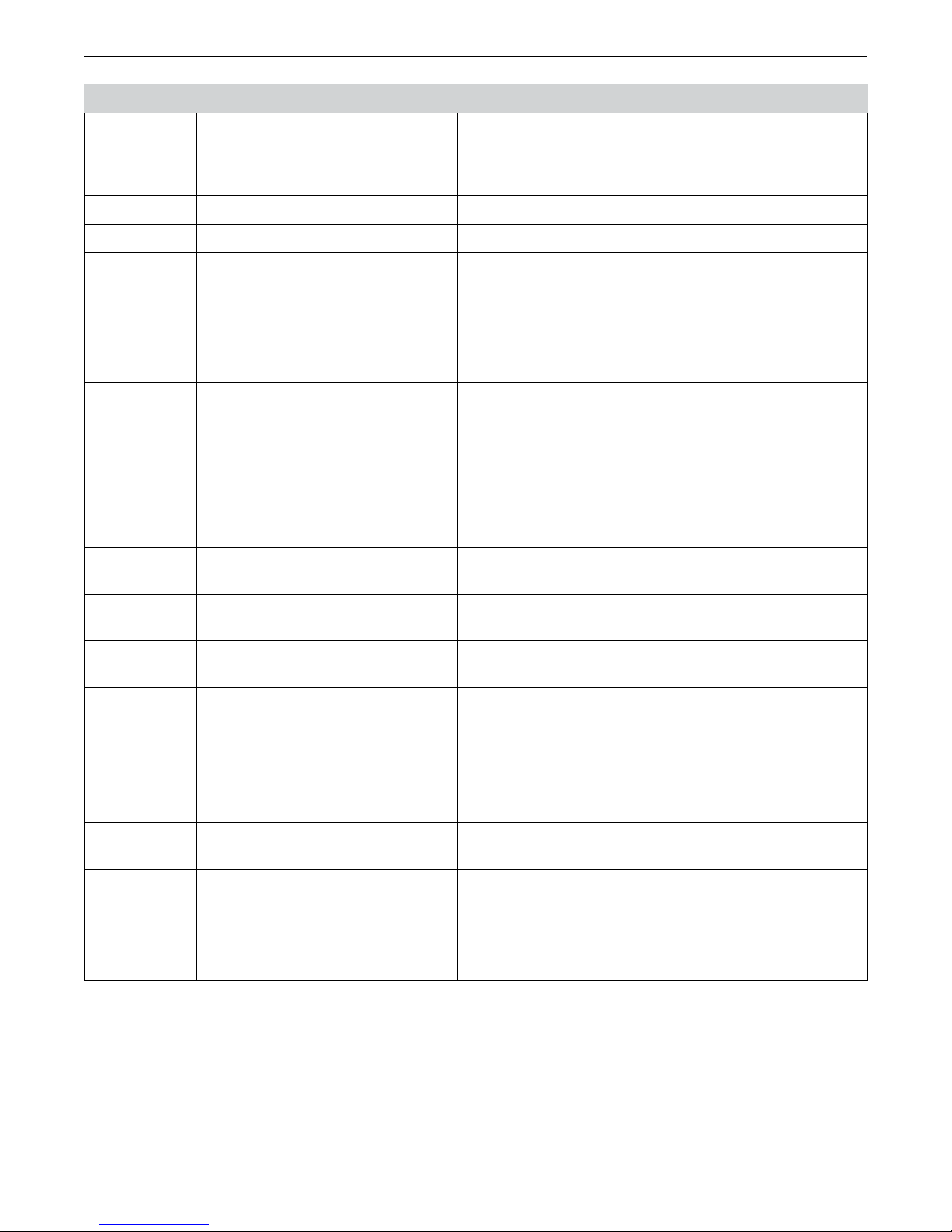
Error Code Description Probable Cause
Er1
(Soft Error)
INVALID ENTRY ERROR: STAGE,
HEAT RATE and TEMP lights flash
Occurs when the HEAT RATE is set to COOL but the TEMP of
that stage is higher than the TEMP of the prior stage (should be
heating). This will occur when a program is already running and
a parameter was edited in process.
Er2 CALIBRATION ERROR Only applies to Factory Calibration.
Er3 RESERVED Reserved for future use.
Er4 (at Idle
temp)
OPEN THERMOCOUPLE Occurs if the thermocouple is open or the connecting wire(s)
are broken or disconnected from the terminal board. If wiring is
good, replace thermocouple.
OR
Er8 (at High
Temps)
OR
The thermocouple output signal becomes intermittent at
elevated temperatures.
Er5 NO HEAT DETECTED/ POSSIBLE The error will be detected 5 minutes after heating program
started. This error will also occur if the program is started and
the chamber door is kept open for 5 minutes or the Solid State
Relay (SSR) is defective, the heater rods are defective or there
is a problem with the main PC board.
Er6 REVERSED THERMOCOUPLE
CONNECTION
Occurs if the thermocouple extension wires have been
connected backwards to the terminals on the printed circuit
board.
Er7 THERMAL RUNAWAY Occurs when the temperature has exceeded 1600˚C (2912°F)
instantly or exceeded 1585°C (2885°F) for 1 minute .
Er8 High Temperature Thermocouple
Replace Thermocouple
failure
Er9 Cavity Temperature Stall Heaters have reached end of useful life, replace all 4 heater
rods.
Er10 Check/Clean Cooling Fan Reminder A slower than normal fan speed is detected indicating the
fan filter may be blocked. It is still able to run a program, but
the filter should be cleaned to restore optimum cooling. This
error will display any time a program is started with a partially
clogged filter. Pressing the Start/Stop button again will launch
the program but the error will persist until the fan is no longer
bogged down by a clogged filter.
Er11 Cooling Fan Lockout A failed cooling fan or a serious filter blockage. Program
running is prevented to prevent further damage to electronics.
Er12 Lift Error Lift is either obstructed or did not reach travel limit sensor and
lift motor timeout was reached Check for jammed table or
sagger tray obstruction.
Er13 Temperature Calcuation Error Possible power surge. Cycle power OFF/ON. If error returns
contact Service.
NOTE: Continuous “Beeps” occur when the Error Code appears on
the Main Display until the START/STOP button is depressed.
18
Page 19
SinterPro Furnace Operator’s Manual
Routine Maintenance
Cleaning Instructions
It is the user’s responsibility not to use decontamination
or cleaning agents that could cause a hazard as a result
of a reaction with parts of the equipment or with material
contained in it. In order to be sure that such a reaction
will not occur, we recommend using only a damp cloth
moistened with water to clean the furnace. Never clean the
Fan Filter Cleaning (Weekly)
display window with a dry cloth or tissue. Always moisten
the cleaning cloth with water before wiping the screen.
Note: If hazardous material is spilled on or inside the
furnace, contact Whip Mix Technical Support if there is any
doubt how to safely remove the material.
An Er10 error code indicates the fan filter is clogged and
the fan has slowed measurably. This error is a reminder
to clean the filter and will not preclude operation but it
will not stop showing up until full fan speed is restored.
An Er11 error code indicates the fan has stopped
turning. This error will inhibit further use of the oven
until the cause is remedied.
CAUTION: DO NOT ALLOW THE FILTER TO BECOME
CLOGGED WITH DUST OR THE CIRCUIT BREAKER CAN
TRIP DUE TO THERMAL OVERLOAD. DO NOT DISCARD
THE FILTER OR DUST CAN ENTER THE ELECTRONICS
AND DAMAGE THEM.
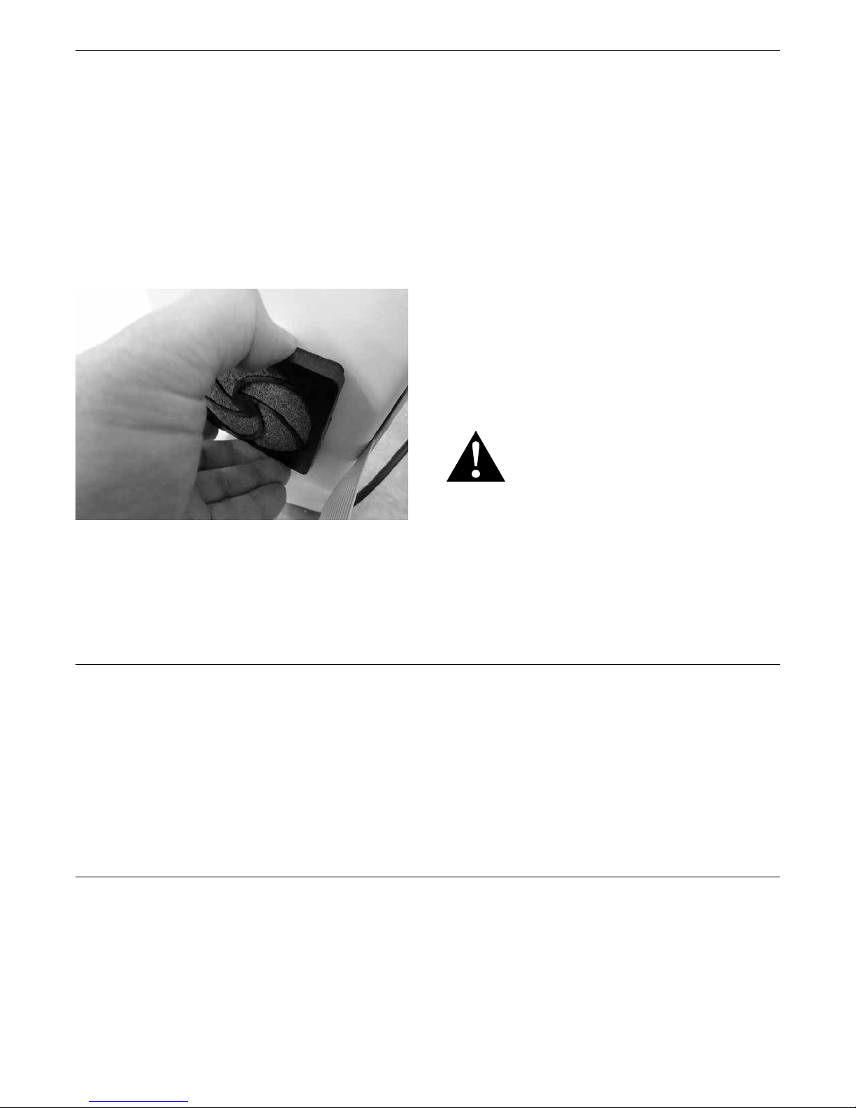
Carefully remove the filter guard by unsnapping the guard to
gain access to the cellular foam filter. Rinse the filter clean
and dry it by blotting it on a paper towel. Slip the filter foam
back inside the guard and press the guard back in place.
An alternative method is to vacuum the filter in place with
the nozzle of a hand vacuum or shop vac.
Power Failure
1. If a power failure occurs, the SinterPro memorizes
the conditions prior to the loss of power. When power
returns, the SinterPro returns to the same point in the
program.
2. When power is returned, the HR:MIN light flashes
indicating that a power failure has occurred. It
continues to flash until START / STOP is pressed.
Service
NOTE: The HR:MIN light flashes if the power switch
is turned off and on while a program is running and
START/STOP was not pressed. It will not flash if the power
switch was turned off or a power failure occurred when the
PROGRAM READY light was on.
CAUTION: The SinterPro Sintering Furnace should be
serviced only by qualified service technicians. Be sure to
unplug the power cord and wait for the furnace to cool
before performing any service operation. For help with
operating or servicing your Whip Mix equipment, please
call Whip Mix any time between 8:00 a.m. and 5:00 p.m.
Eastern time.
Toll Free 1–800–626–5651
Local 1–502–637–1451
FAX 1–502–634–4512
19
Page 20
SinterPro Furnace Operator’s Manual
Lift Preventative Maintenance
WARNING: BEFORE ATTEMPTING ANY OF THE SERVICE
PROCEDURES IN THIS SECTION, BE SURE TO TURN
OFF THE OVEN POWER VIA THE POWER SWITCH AND
DISCONNECT THE OVEN FROM THE WALL POWER,
OR LOCKOUT AND TAG THE WALL CIRCUIT BREAKER
SO THE OVEN CANNOT BE POWERED DURING THE
SERVICING.
As part of the preventative maintenance, it is recommended
to lubricate the lift mechanism every six months or as
necessary for smooth functioning of the lift. Use of
Lubriplate “FGL-2 “grade lubricant or equivalent is highly
recommended in servicing the lift. Following are the steps to
service the lift.
1. Raise or lower the lift platform to the fully up or down
position respectively via the front panel buttons before
turning off the oven. Remove all mains power from the
oven, and unplug the mains power cord for safety.
2. Rotate the furnace so that the back of the chassis is
facing you and leave sufficient space for the bottom
rear panel to lay flat.
3. Remove the rear top cover panel with a phillips
screwdriver leaving the third row of screws (one on
each side) from the top, intact. The third row of screws
need not be removed to remove the top cover panel.
4. Then remove the rear bottom cover panel with phillips
screw driver and lay the panel carefully on the surface
without disturbing the electrical wire connections.
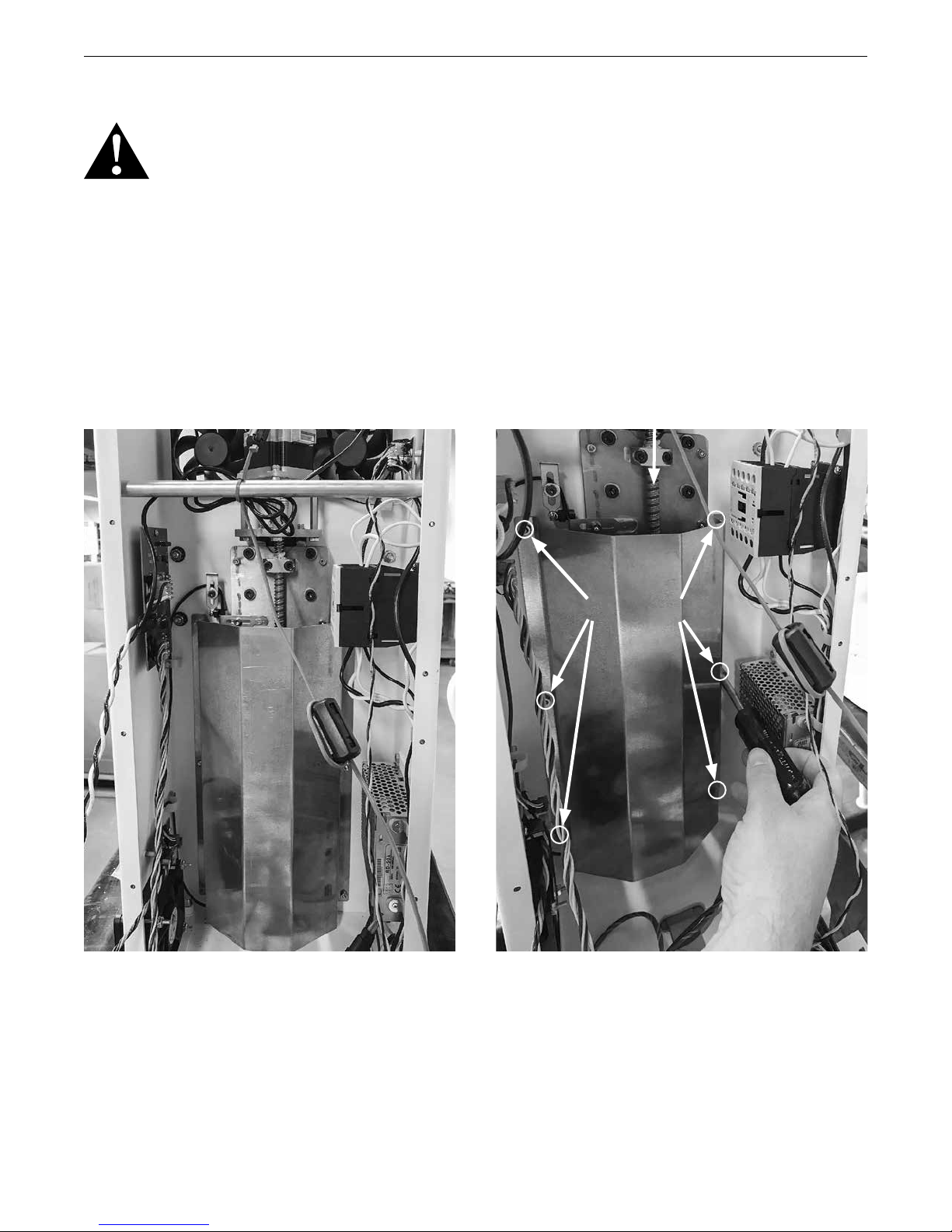
Lead Screw
5. Using an 11/32” nut driver, remove six nuts in the
locations as shown in the above figure.
6. While applying downwards pressure on the EMI shield,
pull it out slowly without catching any electrical wires. It
Nut (6 locations)
EMI Shield
Turn sideways
during removal
(see step 6)
is recommended to turn the shield sideways as shown
in the above figure for easy removal.
7. Clean the lead screw where ever needed, with lint free
rag to remove any dust.
20
Page 21
SinterPro Furnace Operator’s Manual
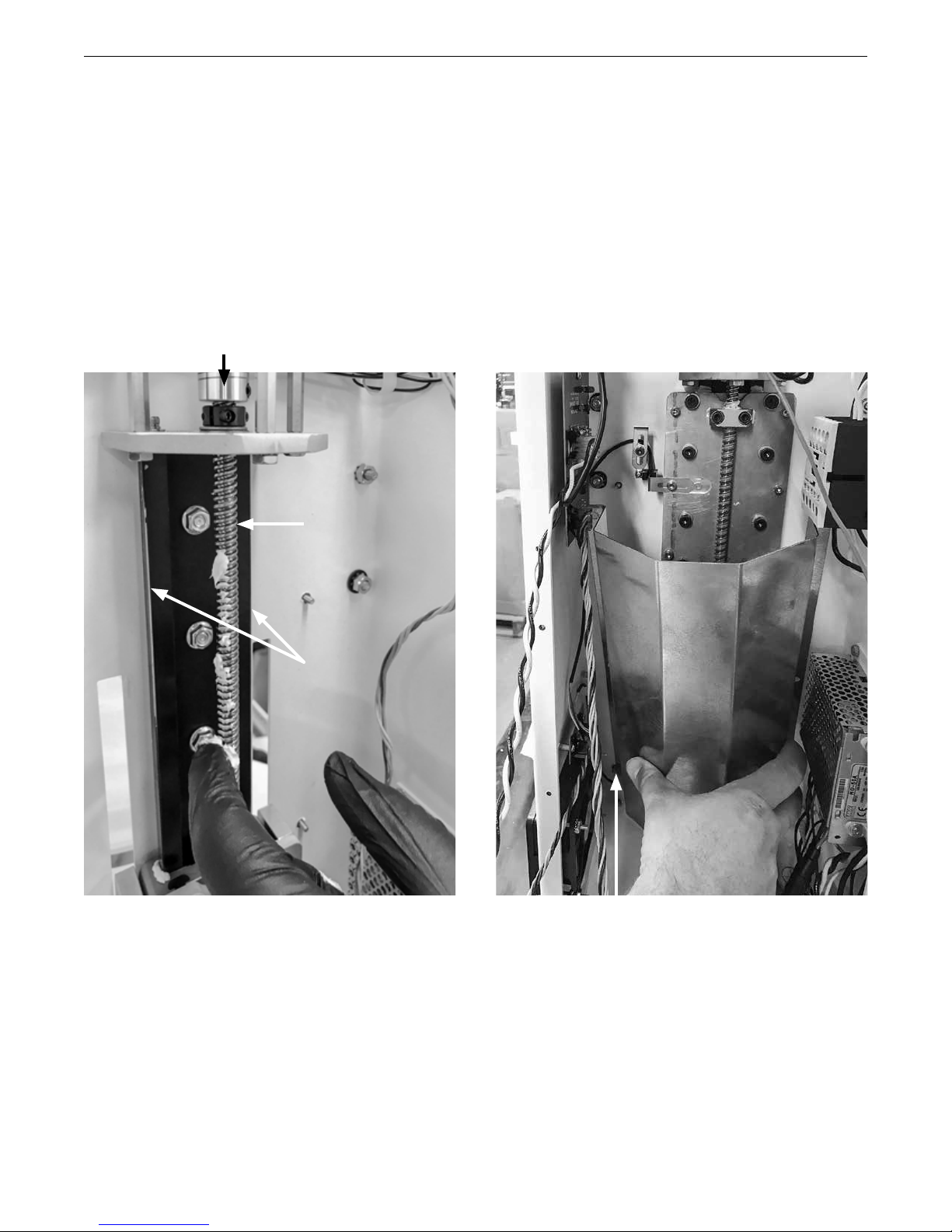
8. Apply recommended lubricant as necessary to the rail
guides and the lead screw along its length as shown in
below figure.
9. Turn the coupler manually to move the lift up and down
to spread the lubricant, repeat step 8 if necessary.
10. Replace the EMI shield back to its position. First, locate
the bottom left hole of the shield on to the mating stud,
ensuring the edge of the shield sits on the wire loop.
Then locate the remaining holes of the shield to the
corresponding studs with downward pressure on the
Coupler
Lead Screw
shield for ease of assembly. Ensure the electrical wire
connections are not disturbed.
11. Secure the shield with nuts using the nut driver.
12. Replace the rear bottom cover panel first ensuring all
the wires are inside the unit without any risk of pinching
the wires while securing the panel with screws.
13. Replace the rear top cover panel and secure it with
screws.
14. Power on the unit and move the lift up and down few
times to spread the lubricant and verify lift functionality.
Rail Guides
Locate this hole first
21
Page 22
SinterPro Furnace Operator’s Manual
Replacement Of Heating Elements
WARNING: BEFORE ATTEMPTING ANY OF THE SERVICE
PROCEDURES IN THIS SECTION, BE SURE TO TURN
OFF THE OVEN POWER SWITCH AND DISCONNECT
THE OVEN FROM THE WALL POWER, OR LOCKOUT
AND TAG THE WALL CIRCUIT BREAKER SO THE OVEN
CANNOT BE POWERED DURING THE SERVICING.
1. Lower the lift platform to the fully down position.
2. Remove all Mains Power from the oven, and unplug the
Mains Power cord for safety.
3. Remove the top panel with a Philips head screwdriver.
4. Two 7/16” box end wrenches are required to remove
the bolts fastening the Heater Element electrical straps.
5. Unplug the two leads connecting the heater wires to
the square white panel on the chassis by grasping
them and gently pulling towards the front of the oven.
They will slide about an inch before disengaging.
6. Remove all six (6) 7/16” bolts interconnecting the
four heater elements. This will require a second 7/16”
wrench on the underside to provide resistance against
the wrench on the upper side.
CAUTION: Do not allow the wrenches to rotate such
that undue strain is placed on the Heating Element,
especially when installing the new Heating Elements.
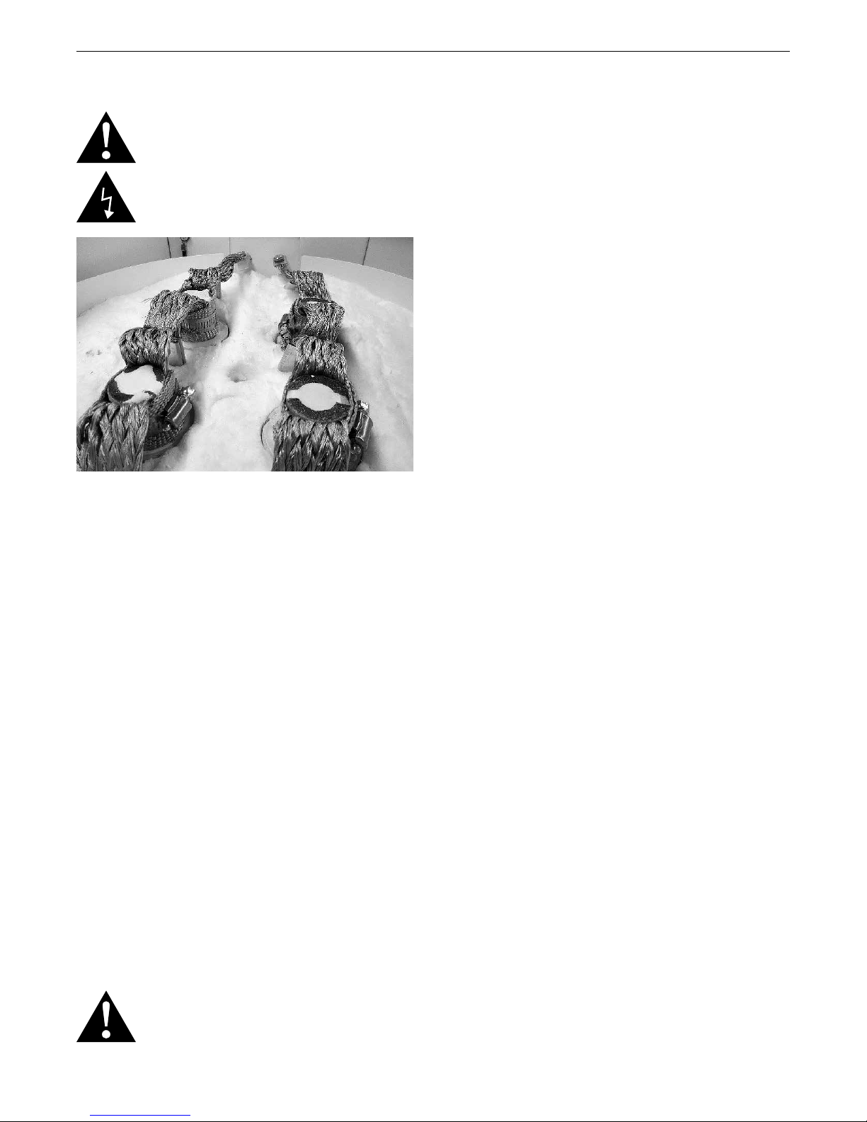
7. Once the bolts have been removed, and each individual
element is free, grasp the white ceramic insulator and
begin raising the Heating Element vertically out of the
roof of the Muffle. Take care not to tilt the element off of
vertical or the insulation may chip away.
8. Withdraw all four elements and set them aside.
9. Unwrap all four of the replacement elements.
10. CAREFULLY lower each element into the hole in the
roof of the Muffle.
CAUTION: UNDER NO CIRCUMSTANCES ATTEMPT TO
ENERGIZE THE MUFFLE WITH ANY OF THE ELEMENTS
NOT INSERTED FULLY!
fully, replace the electrical hardware you removed in
step number 5. Make sure there is a LOCK WASHER
BETWEEN THE STRAPS, then place a lock-washer
on the bolt, then the nut, and tighten securely, taking
care not to twist the elements by tugging on the
electrical straps. Make the connections between the
middle element and the end elements first, then finish
with attaching the end element straps. Plug the two
electrical pins back into the jacks on the chassis
and push them all the way in.
12. Form the loops of the straps with your fingers away
from the center of the ends so that there is maximum
clearance between the straps. Check to make sure
there are no loose strands bridging the two straps.
13. Re-mount the top cover.
14. Power the Oven on.
15. Verify that the Power On Self-Test sequence executed
correctly.
a. The green Heater LED comes on for 1 second, then
goes off.
b. The yellow Alarm1 LED comes on for 1 second,
then goes off.
c. The red Alarm2 LED come on for 1 second, then
goes off.
d. The distinctive “thump” of the Muffle Safety
contactor is heard 1 second after the red LED
goes off.
16. Run a test cycle without anything in the Muffle to verify
normal operation. You may detect an odor during the
first cycle which is due to the new Heater Elements
“breaking-in”. The odor should be gone by the second
or third cycle, and will not return.
NOTE: CLEAR, THIN, GLASS “SOAP BUBBLES” MAY
APPEAR ON THE HEATING ELEMENTS FOR THE FIRST
FEW WEEKS OF OPERATION. THIS IS AN ENTIRELY
NORMAL AND EXPECTED PHENOMENON RESULTING
FROM OXIDATION OF THE SILICON CARBIDE ELEMENTS.
THE BUBBLES RESULT FROM SMALL QUANTITIES OF
CARBON DIOXIDE GAS WHICH IS NON-TOXIC AND NONREACTIVE WITH ZIRCONIA.
NOTE: You may get a “rotten egg” smell and even notice a
slight bit of grey smoke the first time the heaters are fired.
This is NORMAL, and will disappear after the first firing. It is
recommended that you run a complete sintering cycle with
nothing in the muffle to allow the heater rods to outgas fully.
11. After the four elements have been inserted and seated
22
Page 23
SinterPro Furnace Operator’s Manual
Replacement Of Thermocouple
WARNING: BEFORE ATTEMPTING ANY OF THE
SERVICE PROCEDURES IN THIS SECTION, BE SURE
TO TURN OFF THE FURNACE POWER VIA THE POWER
SWITCH AND DISCONNECT THE FURNACE FROM
THE WALL POWER. ENSURE THE FURNACE IS COOL
ENOUGH FOR SAFE HANDLING.
1. Rotate the furnace so that the back of the chassis is
facing you.
2. Remove the top rear cover plate and bottom rear cover
plate with a Phillips screwdriver.
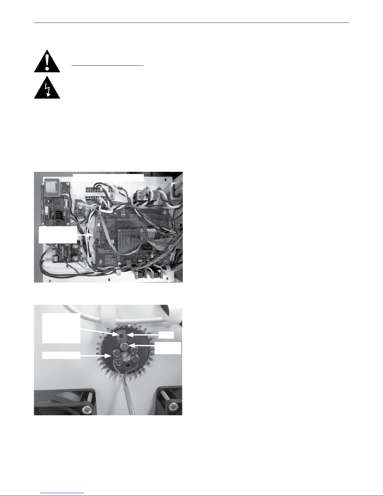
3. Follow the grey cable attached to the thermocouple
downward until you reach a green connector on the
logic circuit board. Gently pull on the connector away
from the circuit card until it disconnects.
Lower Back Panel (removed)
Green
Thermocouple
Connector
4. The thermocouple is recessed inside a 1.6” (4 cm) hole
at about eye height. (see photo)
5. Remove the retainer nut at the 12 o’clock position with
a nut driver.
6. With the clip held in place using a small screw driver
through the clip hole, remove the thermocouple from
the muffle towards you. It is extremely important
to hold the clip through the clip hole with a
small screw driver at all times during removal
or installation of thermocouple. If it is not held
at all times during removal or installation of
thermocouple, it will drop down to the bottom
between the furnace walls.
7. With the clip held in place using a small screw driver
through the clip hole, insert the new thermocouple into
the muffle by gently sliding it in until the ceramic ring
is down in contact with the muffle containment metal
sleeve.
8. Replace the retaining nut at the 12 o’clock position.
This nut does not have to be tightened more than just
enough to retain the brown ring. Overtightening can
cause the brown ring to crack when the muffle gets hot
and expands.
9. Re-connect the green Thermocouple connector to the
green female connector on the logic circuit board.
10. Replace all the back panels with the Phillips screws.
Ensure no wires get pinched when re-attaching the
lower back panel.
11. Power on the furnace.
12. The Temperature Display should read either “IDLE” or
“LO” (<70°C / <158°F).
13. Start a cycle and verify that the Temperature display
begins to climb within 3 – 4 minutes of start.
Hold Clip In
Place With
The Thru Hole
Using A Small
Screw Driver
Thermocouple
Clip
Retaining
Nut
23
Page 24
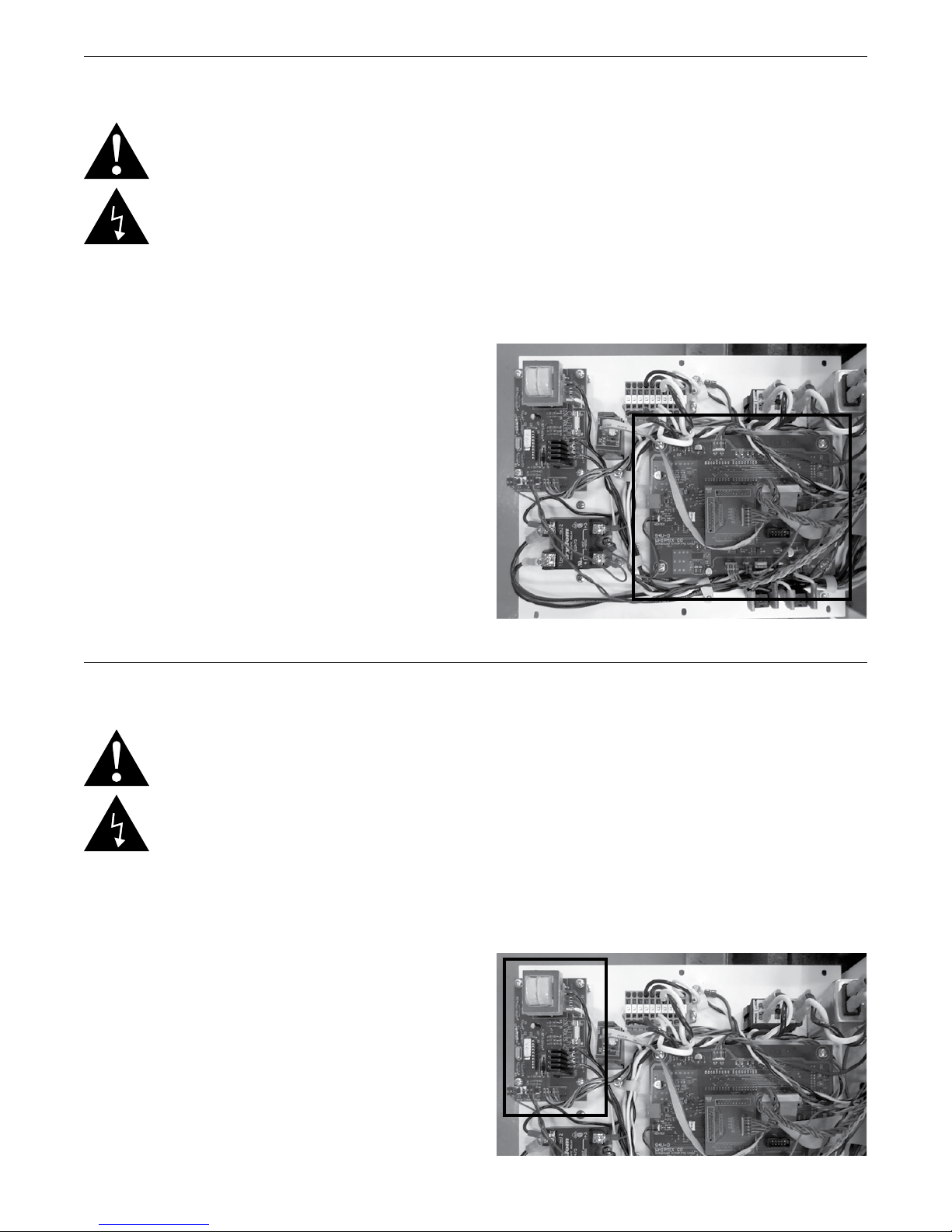
SinterPro Furnace Operator’s Manual
Replacement Of Logic PCB
WARNING: BEFORE ATTEMPTING ANY OF THE SERVICE
PROCEDURES IN THIS SECTION BE SURE TO TURN
OFF THE OVEN POWER VIA THE POWER SWITCH AND
DISCONNECT THE OVEN FROM THE WALL POWER.
Logic PCB Replacement
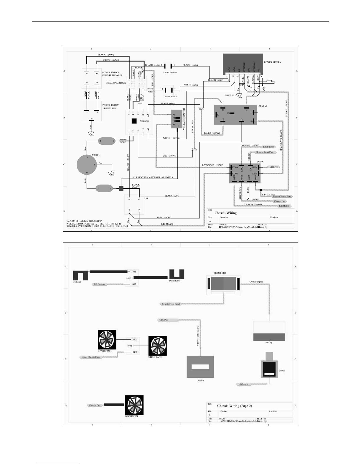
Refer back to the System Wiring Diagram on page 25 for
wiring cable references. The “W” number of the cable
shows where both ends connect.
1. Remove all Power from the oven.
2. Rotate the oven so that you have access to the lower
rear chassis panel.
3. Remove the lower rear panel with a Philips head
screwdriver.
4. Tag all the electrical wiring to match the photograph
above so that you know where to replace the cables.
5. Remove the four hex nuts affixing the logic PCB to the
inside of the chassis.
6. Gently remove the PCB from the studs and set aside.
7. Place the new logic board back onto the same studs,
replace the hex nuts, and tighten.
8. Re-install the cables.
9. Power up the oven and verify the Power On Self-Test
executes properly as below;
a. The green Heater LED comes on for 1 second, then
goes off.
b. The yellow Alarm1 LED comes on for 1 second,
then goes off.
c. The red Alarm2 LED come on for 1 second, then
goes off.
d. The distinctive “click” of the Muffle Safety contactor
is heard 1 second after the red LED goes off.
Replacement Of Alarm PCB
WARNING: BEFORE ATTEMPTING ANY OF THE SERVICE
PROCEDURES IN THIS SECTION BE SURE TO TURN
OFF THE OVEN POWER VIA THE POWER SWITCH AND
DISCONNECT THE OVEN FROM THE WALL POWER.
Alarm PCB Replacement
Refer back to the System Wiring Diagram on the page 25
for wiring cable references. The “W” number of the cable
shows where both ends connect.
1. Remove all Power from the oven.
2. Remove the lower rear panel with a Philips head
screwdriver.
3. Remove the four hex nuts affixing the alarm PCB to the
inside of the chassis.
4. Gently remove the PCB from the studs, and set aside.
5. Place the new Alarm board back onto the same studs,
replace the hex nuts, tighten.
6. Re-install the cables.
7. Power up the oven and verify the Power On Self-Test
executes properly as below;
a. The green Heater LED comes on for 1 second, then
goes off.
b. The yellow Alarm1 LED comes on for 1 second,
then goes off.
c. The red Alarm2 LED come on for 1 second, then
goes off.
d. The distinctive “thump” of the Muffle Safety contac-
tor is heard 1 second after the red LED goes off.
24
Page 25
SinterPro Furnace Operator’s Manual
Replacement Of Solid State Relay
WARNING: BEFORE ATTEMPTING ANY OF THE SERVICE
PROCEDURES IN THIS SECTION BE SURE TO TURN
OFF THE OVEN POWER VIA THE POWER SWITCH AND
DISCONNECT THE OVEN FROM THE WALL POWER.
1. Rotate the oven 180 degrees so that the back of the
oven is facing you.
2. Remove the lower rear panel with a Philips head
screwdriver.
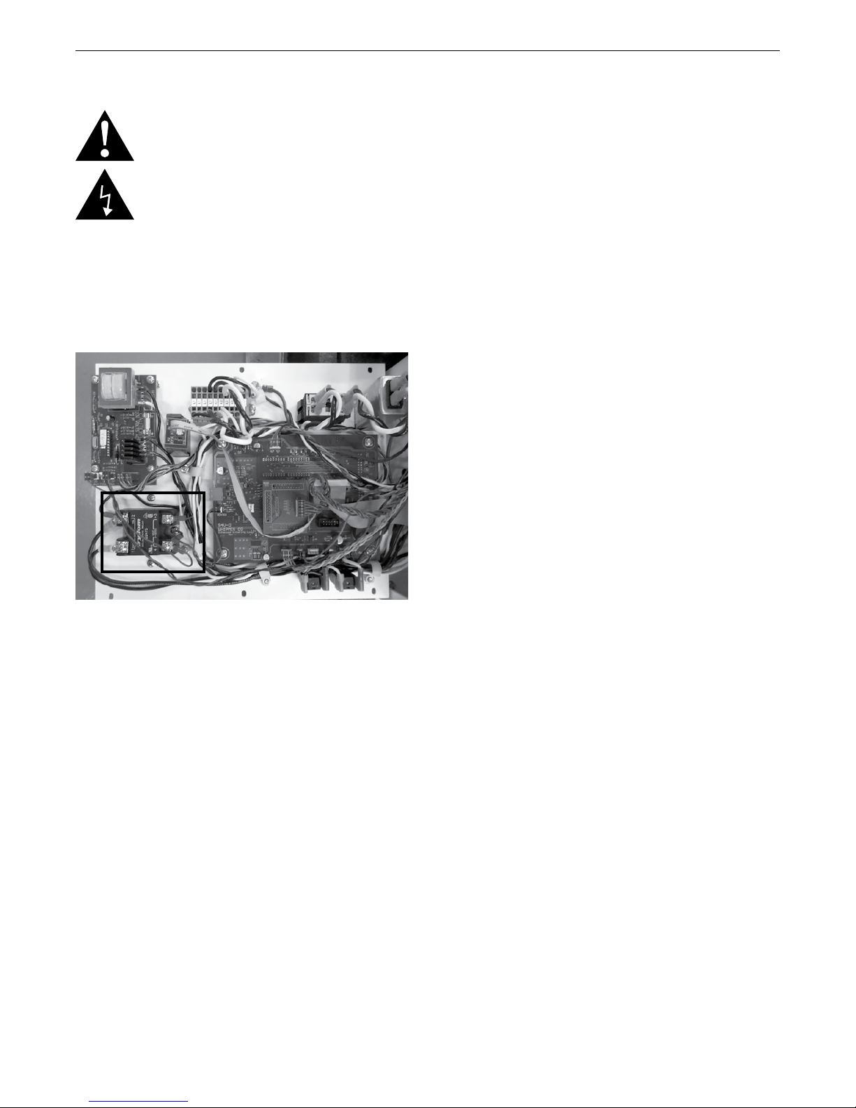
3. Locate the Solid State Relay assembly as pictured
below.
4. Label all of the wires with the numbers marked on
the face of the black Solid State Relay BEFORE
DISCONNECTING!
5. Remove the two mounting screws at the top and
bottom of the Solid State Relay which fasten it to the
black, finned, aluminum heat sink.
6. Insert a small straight-bladed screwdriver between the
Solid State Relay and the black aluminum heat sink
and gently pry the Solid State Relay loose from the
heat sink.
HINT: Use a paper towel or cloth in the hand
supporting the Solid State Relay during the process to
prevent getting any of the white thermally conductive
coating on your hands or your clothes.
7. Once the old Solid State Relay is free in your hand,
use a knife to scrape as much of the white thermally
conductive coating off of the old Solid State Relay as
possible, and transfer it to the new relay. Spread the
white coating around evenly on the new Solid State
Relay, then place it onto the heat sink and smear it
around gently to force out air bubbles and insure good
contact with the heat sink.
HINT: You can let go of the Solid State Relay and the
white coating will hold it in place.
8. Before re-installing the mounting screws, make sure
the Solid State Relay is oriented exactly the way it was
in the photo above.
9. Re-install the two Solid State Relay mounting screws
and tighten securely.
10. Re-connect all the wires by matching up the tags on
the wires with the marking numbers on the face of the
Solid State Relay.
11. Replace the Back Panel on the oven. Make sure the
2 – 3 AMP button circuit breakers are depressed, in
the active position. Rotate the oven 180 degrees to its
operational position.
12. Reconnect the Power Cord to the wall plug.
13. Apply power to the oven via the Mains Power rocker
switch, and verify that the Power On Self-Test does the
following:
a. The green Heater LED comes on for 1 second, then
goes off.
b. The yellow Alarm1 LED comes on for 1 second,
then goes off.
c. The red Alarm2 LED come on for 1 second, then
goes off.
d. The distinctive “click” of the Muffle Safety contactor
is heard 1 second after the red LED goes off.
14. Make sure the Muffle lift platform is raised.
15. If the red Alarm2 LED does NOT go OFF after
several seconds there is a problem with the wiring
associated with the Solid State Relay. A few seconds
afterwards you will hear a second “click” of the Muffle
Safety contactor dropping back out to prevent uncommanded power from reaching the Muffle Heaters.
Remove power from the unit, disconnect it from the
wall, and repeat steps 1-3 above to re-inspect the
wiring. If the wiring is as shown in the photo above, and
all the connections are tight, there may be a secondary
problem with the Alarm PCB attached to the front
panel, or the new Solid State Relay may be defective.
25
Page 26
SinterPro Furnace Operator’s Manual
Replacement Of Voltage Monitor PCB
WARNING: BEFORE ATTEMPTING ANY OF THE SERVICE
PROCEDURES IN THIS SECTION BE SURE TO TURN
OFF THE OVEN POWER VIA THE POWER SWITCH AND
DISCONNECT THE OVEN FROM THE WALL POWER.
1. Remove both the top rear panel and the bottom rear
panel to gain access to the chassis.
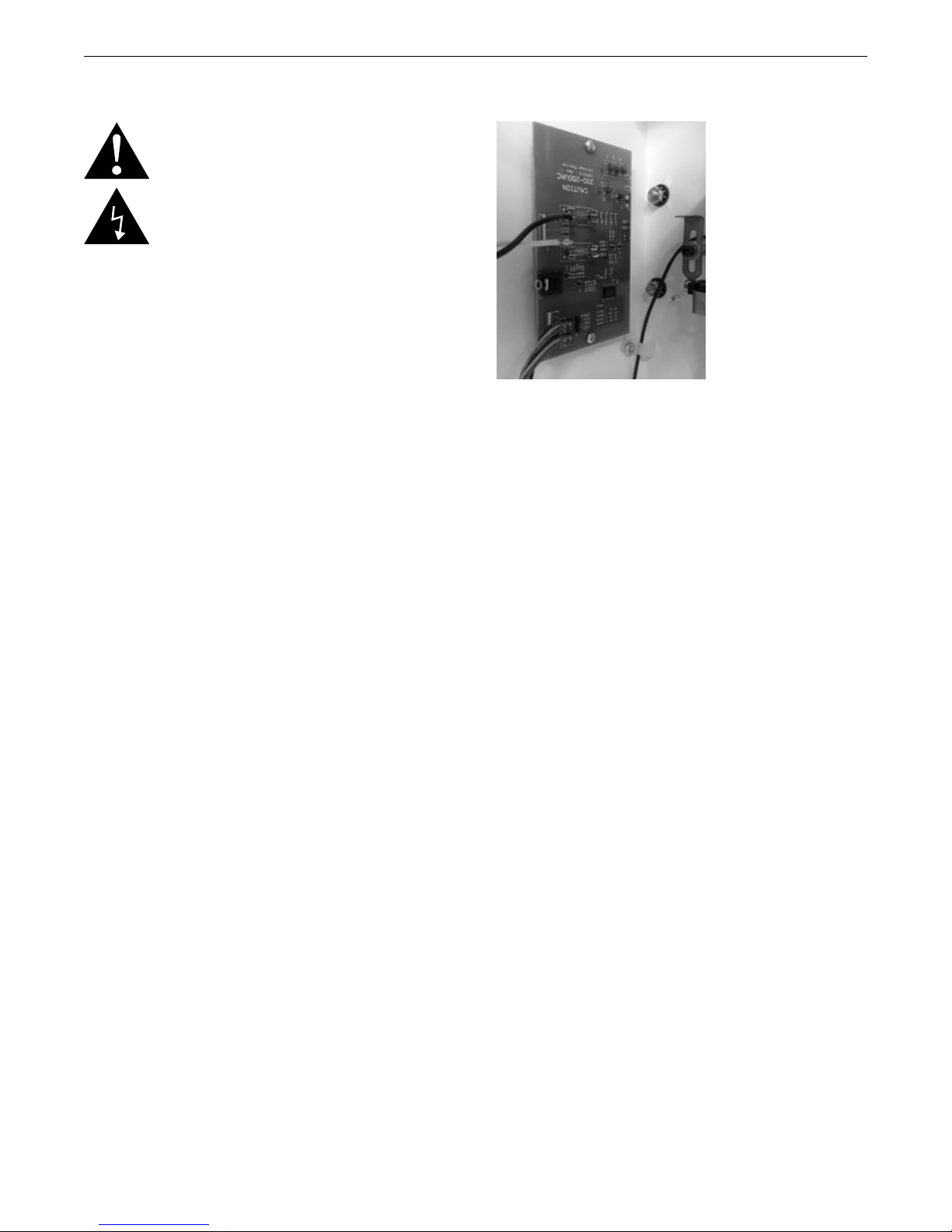
2. Disconnect all the connectors along the edge of the
circuit board as shown in the photo below.
3. Remove the 2 screws.
4. Remove the circuit board and reverse the order of
operations to re-assemble.
26
Page 27
SinterPro Furnace Operator’s Manual
SinterPro Wiring Diagram
27
Page 28

SinterPro Furnace Operator’s Manual
Spare Parts List
Item # Description
96549 8oz Jar of 2mm sized Zirconia Sintering
Beads
96531 Shallow Sintering Tray
96535 Deep Sintering Tray
96537 Sintering Tray Lid
96539 Sintering Tray Forceps
96555 Logic Board
96558 Alarm PCB
96560 Overlay
96562 Heating Elements Pkg 4
96563 Thermocouple - Type B
96565 Display PCB
96566 Power Supply
96567 Contactor
96568 Lower Column Fan Assy(4 Wires)
96564 Upper Column Fan Assy (2 Wires)
96569 Lift Motor
96570 Solid State Relay
96571 Fan Filter
96572 Firing Tray Insulation
96573 Firing Tray Refractory Cap
96540 Fuse, 4Amp, 250 Volt, Glass, 5 X 20 mm for
DC Power Supply
96541 Fuse, 125 MA, 250 Volt, Glass, 5 X 20 mm
for Volt Mon. PCB
96542 Fuse, 50 MA, 250 Volt, Ceramic, 5 X 20 mm
for Alarm PCB
Service
CAUTION: The SinterPro Sintering Furnace should be
serviced only by qualified service technicians. Be sure to
unplug the power cord and wait for the furnace to cool
before performing any service operation. For help with
operating or servicing your Whip Mix equipment, please call
Whip Mix between 8:00 am and 5:00 pm Eastern time.
Toll Free (800) 626–5651
Local (502) 637–1451
FAX (502) 634–4512
IS30125 12/2018
 Loading...