

Page 1
TM
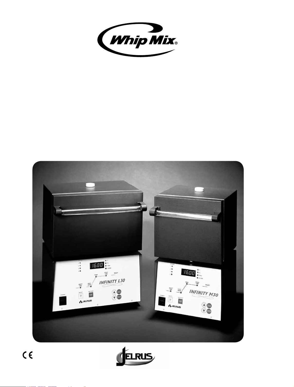
Infinity
Burnout Furnaces
OPERATOR’S MANUAL
Page 2

TABLE OF CONTENTS
Introduction ................................................................2
Warranty ..................................................................2
Safety Instructions . . . . . . . . . . . . . . . . . . . . . . . . . . . . . . . . . . . . . . . . . . . . . . . . . . . . . . . . . . . .2
Specifications ...............................................................
3
Key Parts Identification & Explanation ..............................................4 - 6
Installation .................................................................7 - 8
Operation..................................................................9 - 16
Program and Operate – One Stage Program............................................9
Program and Operate – Two Stage Program ............................................10
Program and Operate – Three Stage Program ...........................................11
Program and Operate – Four Stage Program............................................12
Review a Program ...............................................................13
Edit While a Program is Running.....................................................14
Sample Programs................................................................15
Error Codes ................................................................17 - 18
Service ....................................................................19 - 20
Field Service ................................................................21 - 26
Replacement of Heating Plates ......................................................21
Replacement of Main PC Board .....................................................23
Replacement of Thermocouple Assembly ...............................................25
Replacement of the Triac .......................................................... 26
Thank you for purchasing an Infinity Burnout Furnace.
We have designed and manufactured this furnace using the latest in microcomputer technology to give you many
years of dependable service. The controls on your new Infinity are different from those you may be used to on an
ordinary burnout furnace. To ensure that your Infinity Burnout Furnace gives you the highest level of service, review
and follow the guidelines outlined in this Operator’s Manual.
WARRANTY
This Jelrus equipment is warranteed to be free from defects in material and workmanship from the date of installation
for a period of twelve months (the muffle on our furnaces are waranted for 24 months).
Any item returned to Whip Mix will be repaired or replaced at our option at no charge provided that our inspection
shall indicate it to have been defective. Dealer, labor, shipping and handling charges are not overed by this war-
ranty.
This warranty does not apply to damage due to shipping, misuse, careless handling or repairs by other than autho-
rized service personnel. Whip Mix is not liable for indirect or consequential damage or loss of any nature in con-
nection with this equipment.
This warranty is in lieu of all other warranties expressed or implied. No representative or person is authorized to
assume for us any liability in connection with the sale of our equipment.
Use of the Infinity furnace not in conformance with the instructions specified in this manual may result in premture
failure of the unit.
WARNING: To prevent fire or electrical shock, do not expose this appliance to rain or moisture.
Spare Parts List ..............................................................27 - 28
Program Cards ..............................................................29 - 30
1
ATTENTION USERS:
Do Not Attempt Internal Service
The interior of the Main Assembly is only accessible by removing hardware with tools and should only be opened
and serviced by qualified technicians. Since the interior of the unit may contain high voltage and dangerous com-
ponents, failure to heed this warning may result in equipment damage, personal injury and/or death.
Please call Whip Mix between 8:00 a.m. and 5:00 p.m. (EST) for service information.
Page 3
INTRODUCTION
Thank you for purchasing an Infinity Burnout Furnace.
We have designed and manufactured this furnace using the latest in microcomputer technology to give you many
years of dependable service. The controls on your new Infinity are different from those you may be used to on an
ordinary burnout furnace. To ensure that your Infinity Burnout Furnace gives you the highest level of service, review
and follow the guidelines outlined in this Operator’s Manual.
WARRANTY
This Jelrus equipment is warranteed to be free from defects in material and workmanship from the date of installation
for a period of twelve months (the muffle on our furnaces are waranted for 24 months).
Any item returned to Whip Mix will be repaired or replaced at our option at no charge provided that our inspection
shall indicate it to have been defective. Dealer, labor, shipping and handling charges are not overed by this warranty.
This warranty does not apply to damage due to shipping, misuse, careless handling or repairs by other than authorized service personnel. Whip Mix is not liable for indirect or consequential damage or loss of any nature in connection with this equipment.
This warranty is in lieu of all other warranties expressed or implied. No representative or person is authorized to
assume for us any liability in connection with the sale of our equipment.
SAFETY INSTRUCTIONS
Use of the Infinity furnace not in conformance with the instructions specified in this manual may result in premture
failure of the unit.
WARNING: To prevent fire or electrical shock, do not expose this appliance to rain or moisture.
ATTENTION USERS:
This symbol alerts the user that important
Operating and Maintenance instructions
have been included with the unit. Read
carefully to avoid any problems.
Do Not Attempt Internal Service
The interior of the Main Assembly is only accessible by removing hardware with tools and should only be opened
and serviced by qualified technicians. Since the interior of the unit may contain high voltage and dangerous components, failure to heed this warning may result in equipment damage, personal injury and/or death.
Please call Whip Mix between 8:00 a.m. and 5:00 p.m. (EST) for service information.
This symbol warns the user that uninsulated
voltage within the unit may be of sufficient
magnitude to cause electric shock.
2
Page 4
SPECIFICATIONS
INFINITY M–30 INFINITY L–30
Electrical
Capacity
Overall
Dimensions
Heating
Chamber
Dimensions
INFINITY M–30 AND L–30
Number of Programs
NIGHT TIME
(DELAY START)
115V 50/60Hz 1150W
220/230V 50/60Hz 1150W
8-1 3/4” rings or 2–3” rings
10-3/4”W x 13-7/8”D x 18– 3/4”H
(27.3cm x 35.2cm x 47.6cm)
5-1/2”W x 5-1/4”D x 5-1/8”H
(14.0cm x 13.3cm x 13.0cm)
30
0 – 99 hours
Note: This is the time required for the program to be completed
and ready to cast.
115V 50/60Hz 1610W
220/230V 50/60Hz 1610W
15-1 3/4” rings or
5-1 3/4” rings and 3-3” rings
14-1/2”W x 14-3/8”D x 18-3/4”H
(36.8cm x 36.5cm x 47.6cm)
9-1/8”W x 5-1/4”D x 5-1/8”H
(23.2cm x 13.3cm x 13.0cm)
HEAT RATE
(Stage 1)
HEAT RATE
(Stages 2, 3, & 4)
TEMPERATURE
HOLD TIME
*
Programmable heat rates. Actual heat rate at high temperatures may be lower depending upon furnace load
and electrical voltage.
*
*
a) 1 – 30°F/min. (1 – 17°C/min.)
b) “FULL” Stage heats at the maximum rate attainable.
a) 1 – 30°F/min. (1 – 17°C/min.)
b) “FULL” Stage heats at the maximum rate attainable.
c) “NO” Stage is not used.
d) “COOL” Stage cools down to the programmed temperature.
Note: If “NO” is selected for a stage, that stage and all subsequent
stages will not be used. The furnace, therefore, can be used for one,
two, three or four stage operation.
a) Stage 1: 150°F – 2012°F (66°C – 1100°C)
b) Stage 2, 3, 4: 100°F – 2012°F (38°C – 1100°C)
0 – 4 hours
3
Page 5

KEY PARTS IDENTIFICATION AND EXPLANATION
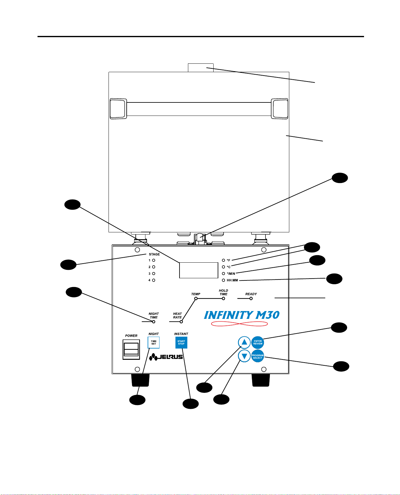
FRONT PANEL (Figure 1)
DISPLAY
1. NIGHT TIME Press to start a delayed program. The number entered is the time
(DELAY START) required for the program to be COMPLETED AND READY TO CAST.
When a program is running, press to display the time remaining to
complete the program.
2. START / STOP Press to start or stop a program.
3. Press to increase a number. The longer the button is pressed, the
faster the numbers change.
4. Press to decrease a number. The longer the button is pressed, the
faster the numbers change.
5. ENTER / REVIEW When programming or reviewing a program in process, press to
advance to the next parameter.
6. PROGRAM SELECT Press to select a program or to review the program currently running.
7. STAGE 1–2–3–4 While programming, the number of active stages are illuminated. In
the burnout process, the current STAGE flashes.
DESCRIPTION
8. °F and °C Identifies the temperature scale.
9. °/ MIN Identifies the heat rate.
10. HH : MM Indicates time. When flashing it indicates that a power failure has
occurred.
11. Main Display A. The 4 digit display indicates the chamber temperature.
B. When programming or reviewing, indicates PROGRAM NUMBER,
NIGHT TIME (DELAY START) (time to completion), HEAT RATE,
TEMP and HOLD TIME.
C. Displays special words and error codes.
12. Program Status Graph Indicates status of the burnout process.
13. Door Interlock Shuts off electrical power from the heating plates
Safety Switch when the furnace door is opened.
4
Page 6
KEY PARTS IDENTIFICATION AND EXPLANATION
11
Vent
Tube
Heating
Chamber
13
8
7
12
3
1
2
4
9
10
Front
Panel
5
6
Figure 1
INFINITY M–30 AND L–30 IDENTIFICATION
5
Page 7
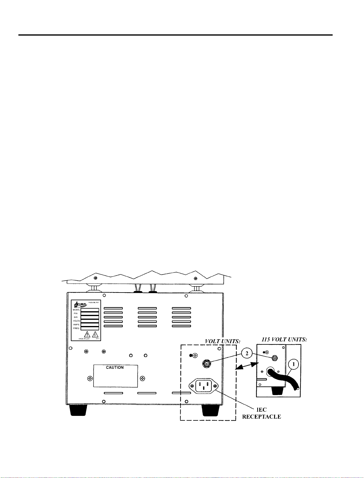
KEY PARTS IDENTIFICATION AND EXPLANATION
LOWER BACK PANEL (Figure 2)
DISPLAY DESCRIPTION
1. Power Cord A. On 115V furnaces, the AC power cord is permanently
connected to the unit.
B. On 220/230V furnaces, the AC power cord is detachable and
connects to a standard IEC receptacle.
C. AC power cords are provided to correspond to receptacles that are available
in a specific country.
2. Circuit Breaker Protects circuitry from electrical overload.
•Blackbuttonwill“popout”ifoverloadispresent.
•Toreset,waitoneminuteandpushblackbuttonintobodyofcircuitbreaker.
Figure 2
INFINITY LOWER BACK PANEL
220/230
6
Page 8

INSTALLATION
UNPACK AND SET–UP
1. Unpack the contents of the box. Remove the following materials:
A. Vent Tube – Remove from bubble wrap and insert in hole on top of furnace.
B. Calibration Table Kit – Remove plastic bag containing two tablets and save for future use.
C. Burnout Tray – Remove tray(s) from bubble wrap and install on the floor of the chamber.
2. Place the furnace in position allowing a minimum of 2 inches (5 cm) of air space on all sides.
3. Plug the power cord into a wall receptacle. On 220/230V furnaces, first connect the power cord
to the IEC receptacle located on the rear of the furnace. A separate electrical circuit is recommended.
The voltage rating of your furnace is on the serial number plate.
4. The furnace is now ready for operation.
CAUTIONS:
Do not install closer than 2" (5cm) from any combustible material. DO NOT BLOCK VENT
HOLE ON TOP OF THE FURNACE. Hot gases are vented through this hole.
TO SET TEMPERATURE SCALE (Figure 1)
115V furnaces are pre-set in degrees Fahrenheit.
220/230V furnaces are pre-set in degrees Celsius.
1. Turn the power switch on. (If the furnace is already on, be sure it is in the idle mode – no program is
running.) The chamber temperature appears on the Main Display and the °C or °F light goes on.
2. Press
at the same time. The degree light switches to the opposite temperature scale.
7
Page 9

INSTALLATION
TO TURN THE “BEEP” ON AND OFF (Figure 1)
When a program is completed, 20 "beeps" sound every 15 minutes to remind the operator that the
material is ready to cast.
1. Be sure the Infinity is in the idle mode – no program us running.
2. Press and (while holding) press PROGRAM NUMBER to display the status of the "beep."
"ON" indicates the beep is active. "OFF" indicates the beep is inactive.
3. Use either of the to turn the "beeps" on or off.
4. To return to the idle mode, wait 7 seconds or press STOP / START twice. (If STOP / START
is pressed once, cycle starts.)
8
Page 10

OPERATION
PROGRAM AND OPERATE – ONE STAGE PROGRAM (Figure 1)
1. Turn the power switch on.
2. Press PROGRAM NUMBER. Use to display the desired program number (P1 – P30).
3. Press ENTER / REVIEW to select the displayed PROGRAM NUMBER. STAGE 1 and NIGHT TIME
(DELAYED START) lights turn on. Enter to set the time required for the program to be completed and
ready to cast (1 – 99hrs).
4. Press ENTER / REVIEW. STAGE 1 light remains on, NIGHT TIME (DELAY START) light turns off and
HEAT RATE light turns on. Enter to select the heat rate required from 1°F – 30°F / min
o
(1
5. Press ENTER / REVIEW. STAGE 1 light remains on, HEAT RATE light turns off and TEMP light turns on.
Enter to select the temperature required up to the maximum of 2012°F (1100°C).
6. Press ENTER / REVIEW. STAGE 1 light remains on, TEMP light turns off and HOLD TIME light turns on.
Enter to program the time needed to hold at above temperature. (0 – 4hrs).
7. For one stage, the furnace must be programmed not to use STAGE 2, 3 or 4. Follow these steps:
A. After completing step 6, press ENTER / REVIEW. STAGE 1 light turns off, STAGE 2 and HEAT RATE
lights turn on.
B. Press Main Display shows ".....5, 4, 3, 2, 1, COOL, NO." Select "NO" to
program the furnace not to use STAGE 2, 3 or 4.
8. All necessary information for this program is now entered.
C – 17oC / min) or "FULL" for the maximum heat rate.
9. To run the program immediately, press START / STOP.
10. To delay the start of the program to be ready to cast at the pre-set time (see Step 3), press NIGHT TIME
(DELAY START).
NOTE: If NIGHT TIME (DELAY START) is pressed while a program is running, the time
remaining for completion of the program will appear on the Main Display
for 5 seconds.
9
Page 11

OPERATION
PROGRAM AND OPERATE – TWO STAGE PROGRAM (Figure 1)
1. Follow One Stage Program, Steps 1 – 6.
2. Press ENTER / REVIEW. STAGE 1 light turns off, STAGE 2 and HEAT RATE lights turn on. Main
Display shows four heat rate choices. Choose one:
A. Select heat rate between 1°F – 30°F / min (1°C – 17°C / min) using .
B. Select "FULL" to program maximum heat rate.
C. Select "COOL" to program the furnace to cool to a selected temperature.
D. Select "NO" to turn of STAGE 2, 3 and 4. This will result in a One Stage Program.
NOTE: The HEAT RATE cannot be programmed to "COOL" in STAGE 1 – only in STAGE 2,
3 or 4.
3. Press ENTER / REVIEW. HEAT RATE light turns off and TEMP light turns on. Enter for the
temperature required: heating temperature up to a maximum of 2012°F (1100°C) or cooling
temperature down to a minimum of 100°F (38°C).
4. Press ENTER / REVIEW. TEMP light turns off and HOLD TIME light turns on. Enter to program the
time needed to hold at the above temperature (0 – 4hrs.).
5. For two stages, the furnace must be programmed not to use STAGE 3 or 4. Follow these steps:
A. After completing Step 4, press ENTER / REVIEW. STAGE 2 light turns off, STAGE 3 and HEAT
RATE lights turn on.
B. Press Main Display shows “....5,4,3,2,1, COOL, NO.” Select “NO” to program the
furnace not to use STAGE 3 or 4.
6. All necessary information for this program is now entered.
7. To run the program immediately, press START / STOP.
8. To delay the start of the program to be ready to cast at the pre–set time (see One Stage Program,
Step 3), press NIGHT TIME (DELAY START).
NOTE: If NIGHT TIME (DELAY START) is pressed while a program is running, the time
remaining for completion of the program will appear on the Main Display for 5
seconds.
10
Page 12

OPERATION
PROGRAM AND OPERATE – THREE STAGE PROGRAM (Figure 1)
1. Follow Two Stage Program, Steps 1 – 4.
2. Press ENTER / REVIEW. STAGE 2 light turns off, STAGE 3 and HEAT RATE lights turn on. Main
Display shows four heat rate choices. Choose one:
A. Select heat rate between 1°F – 30°F /min (1°C – 17°C /min) using .
B. Select "FULL" to program maximum heat rate.
C. Select "COOL" to program the furnace to cool to a selected temperature.
D. Select "NO" to turn of STAGE 3 and 4. This will result in a Two Stage Program.
NOTE: The HEAT RATE cannot be programmed to "COOL" in STAGE 1 – only in STAGE
2, 3 or 4.
3. Press ENTER / REVIEW. HEAT RATE light turns off and TEMP light turns on. Enter for the
temperature required: heating temperature up to a maximum of 2012°F (1100°C) or cooling
temperature down to a minimum of 100°F (38°C).
4. Press ENTER / REVIEW. TEMP light turns off and HOLD TIME light turns on. Enter to program the
time needed to hold at the above temperature (0 – 4hrs.).
5. For three stages, the furnace must be programmed not to use STAGE 4. Follow these steps:
A. After completing Step 4, press ENTER / REVIEW. STAGE 3 light turns off, STAGE 4 and HEAT
RATE lights turn on.
B. Press . Main Display shows “....5,4,3,2,1, COOL, NO.” Select “NO” to program the
furnace not to use STAGE 4.
6. All necessary information for this program is now entered.
7. To run the program immediately, press START / STOP.
8. To delay the start of the program to be ready to cast at the pre-set time (see One Stage Program,
Step 3), press NIGHT TIME (DELAY START).
NOTE: If NIGHT TIME (DELAY START) is pressed while a program is running, the time
remaining for completion of the program will appear on the Main Display
for 5 seconds.
11
Page 13

OPERATION
PROGRAM AND OPERATE – FOUR STAGE PROGRAM (Figure 1)
1. Follow Three Stage Program, Steps 1 – 4.
2. Press ENTER/REVIEW. STAGE 3 light turns off, STAGE 4 and HEAT RATE lights turn on. Main
Display shows four heat rate choices. Choose one:
A. Select heat rate between 1°F – 30°F/min (1°C – 17°C/min) using .
B. Select “FULL” to program maximum heat rate.
C. Select “COOL” to program the furnace to cool to a selected temperature.
D. Select “NO” to turn off Stage 4. This will result in a Three Stage Program.
NOTE: The HEAT RATE cannot be programmed to “COOL” in STAGE 1 –
only in STAGE 2, 3 or 4.
3. Press ENTER/REVIEW. HEAT RATE light turns off and TEMP light turns on. Enter for the temperature
required : heating temperature up to a maximum of 2012°F (1100°C) or cooling temperature down
to a minimum of 100°F (38°C).
4. Press ENTER/REVIEW. TEMP light turns off and HOLD TIME light turns on. Enter to program the
time needed to hold at the above temperature (0 – 4 hrs.).
5. All necessary information for this program is now entered.
6. To run the program immediately, press START/STOP.
7. To delay the start of the program to be ready to cast at the pre–set time (see One Stage Program,
Step 3 ), press NIGHT TIME (DELAY START).
NOTE: If NIGHT TIME (DELAY START) is pressed while a program is running, the time
remaining for completion of the program will appear on the Main Display
for 5 seconds.
12
Page 14

OPERATION
REVIEW A PROGRAM (Figure 1)
1. Turn the power switch on.
2. Press PROGRAM NUMBER.
3. Press to select the program number to be reviewed. The PROGRAM NUMBER (P1 – P30)
will appear on the Main Display.
4. The number of stages in the program are indicated by the STAGE lights next to the Main Display.
5. Press ENTER / REVIEW. NIGHT TIME (DELAY START) light turns on. The number of hours entered for the
entire program to be completed and ready to cast appears on the Main Display. After 7 seconds, if no
other button is pressed, NIGHT TIME (DELAY START) light turns off and the actual furnace temperature
appears on the Main Display.
6. Press ENTER / REVIEW again. If 7 seconds has not elapsed, the HEAT RATE light turns on. If 7 seconds
has already elapsed and the furnace temperature appears on the Main Display, press ENTER / REVIEW
twice. First the NIGHT TIME (DELAY START) light turns on and then the HEAT RATE light turns on. When the
HEAT RATE light is on, the programmed heat rate appears on the Main Display.
NOTE: STAGE 1 light is now on.
7. Press ENTER / REVIEW and TEMP light turns on. The programmed temperature (TEMP) for STAGE 1
appears on the Main Display.
8. Press ENTER / REVIEW and HOLD TIME light turns on. The programmed HOLD TIME for STAGE 1
appears on the Main Display in HR : MIN.
9. All of the information in STAGE 1 has now been entered. If ENTER / REVIEW is pressed again, STAGE 2
light turns on. Review STAGE 2 following the same procedure as above. Continue pressing
ENTER / REVIEW to review all of the individual parameters in STAGE 2, 3, or 4.
NOTE: NIGHT TIME (DELAY START) appears only at the very beginning of STAGE 1.
13
Page 15

OPERATION
EDIT WHILE A PROGRAM IS RUNNING (Figure 1)
1. To identify which program is running, press PROGRAM NUMBER.
NOTE: The program number cannot be changed using while the program is running.
2. To determine the time remaining for the completion of the program, press NIGHT TIME (DELAY START).
The time remaining appears on the Main Display for 5 seconds.
3. Any individual parameter can be increased or decreased during the actual running of all 30
programs.
NOTE: HEAT RATE cannot be changed to "NO" in the stage currently running or in the
stages already completed.
4. To change a parameter while a program is running, press ENTER / REVIEW to advance to the desired
STAGE and parameter (i.e. HEAT RATE, TEMP or HOLD TIME). Initially, STAGE 1 will appear.
Any parameter can be increased or decreased by pressing or .
5. Any program can be stopped or started by pressing the START / STOP button.
6. If a program is edited while running and the HEAT RATE in STAGE 2, 3 or 4 is set to "COOL" but the
corresponding TEMP programmed is entered to heat to a higher temperature than the previous stage,
the Infinity will try to heat with a 0°F / Min (0°C / Min) HEAT RATE. In this case, when NIGHT
TIME (DELAY START) is pressed, 99:99 (Hr : Min) flashes on the Main Display, indicating that the
program cannot be completed.
14
Page 16
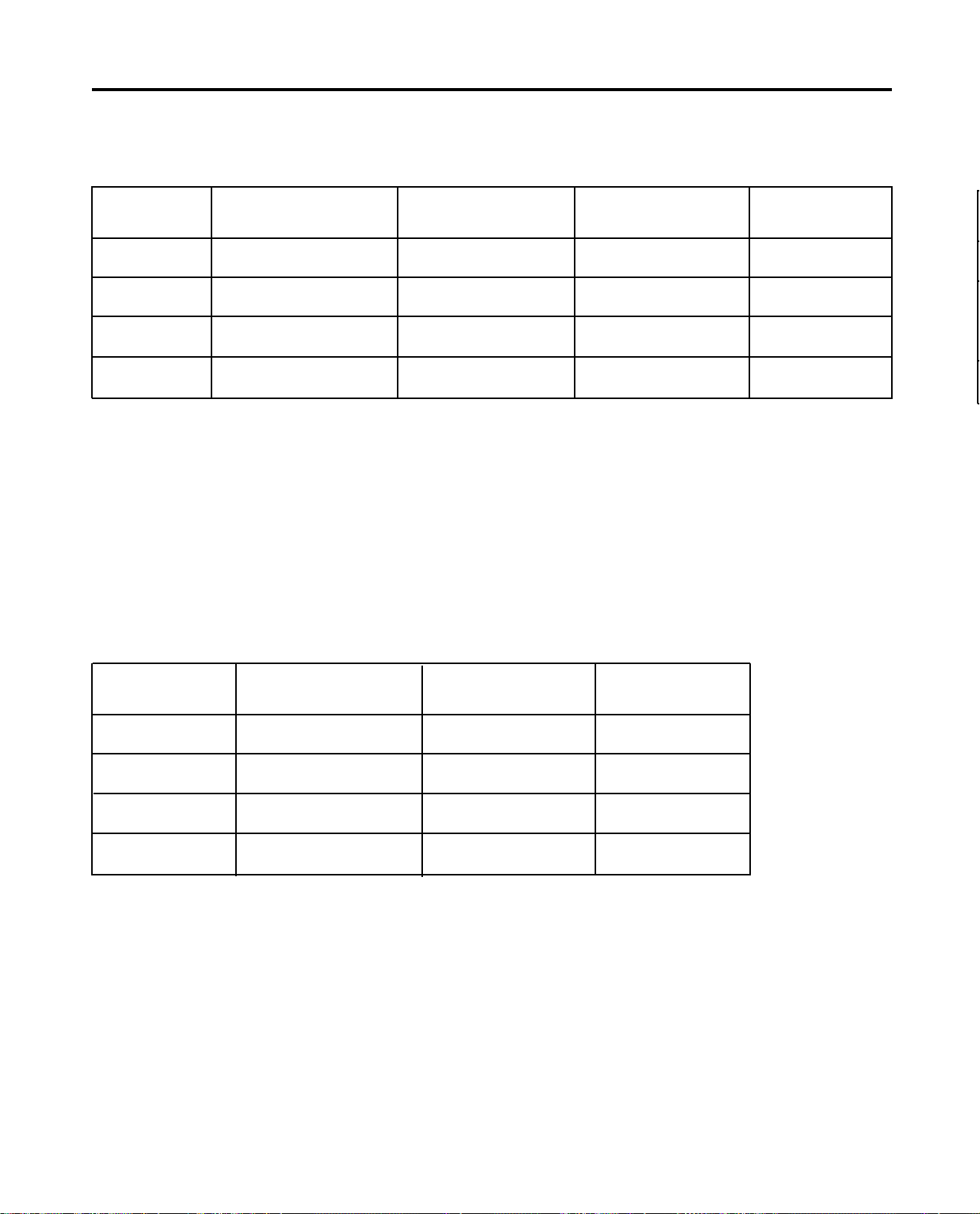
OPERATION
SAMPLE ONE STAGE PROGRAM
(To be completed and ready to cast in 24 hours)
NIGHT TIME
DELAY START
STAGE 1
STAGE 2
STAGE 3
STAGE 4
*Though any number may appear, the unit is deactivated when “NO” is selected for the HEAT RATE.
NOTE: To turn off STAGE 2,3 and 4, select “NO” for the HEAT RATE in STAGE 2.
Press NIGHT TIME (DELAY START). Infinity automatically turns on at the correct time to complete the program
and be ready to cast in 24 hours.
SAMPLE TWO STAGE PROGRAM
(To start immediately)
24:00
HEAT RATE
10°F (6°C)
NO
NO
NO
TEMP
1600°F (871°C)
*
*
*
HOLD TIME
1:00
*
*
*
HEAT RATE
STAGE 1
STAGE 2
STAGE 3
STAGE 4
*Though any number may appear, the unit is deactivated when “NO” is selected for the HEAT RATE.
NOTE: To turn off STAGE 3 & 4, select “NO” for the HEAT RATE in STAGE 3.
To start immediately, press START / STOP.
Follow the same programming procedures if a three or four stage program is desired.
10°F (6°C)
20°F (11°C)
NO
NO
TEMP
600°F (316°C)
1600°F (871°C)
*
*
HOLD TIME
30
1:00
*
*
15
Page 17
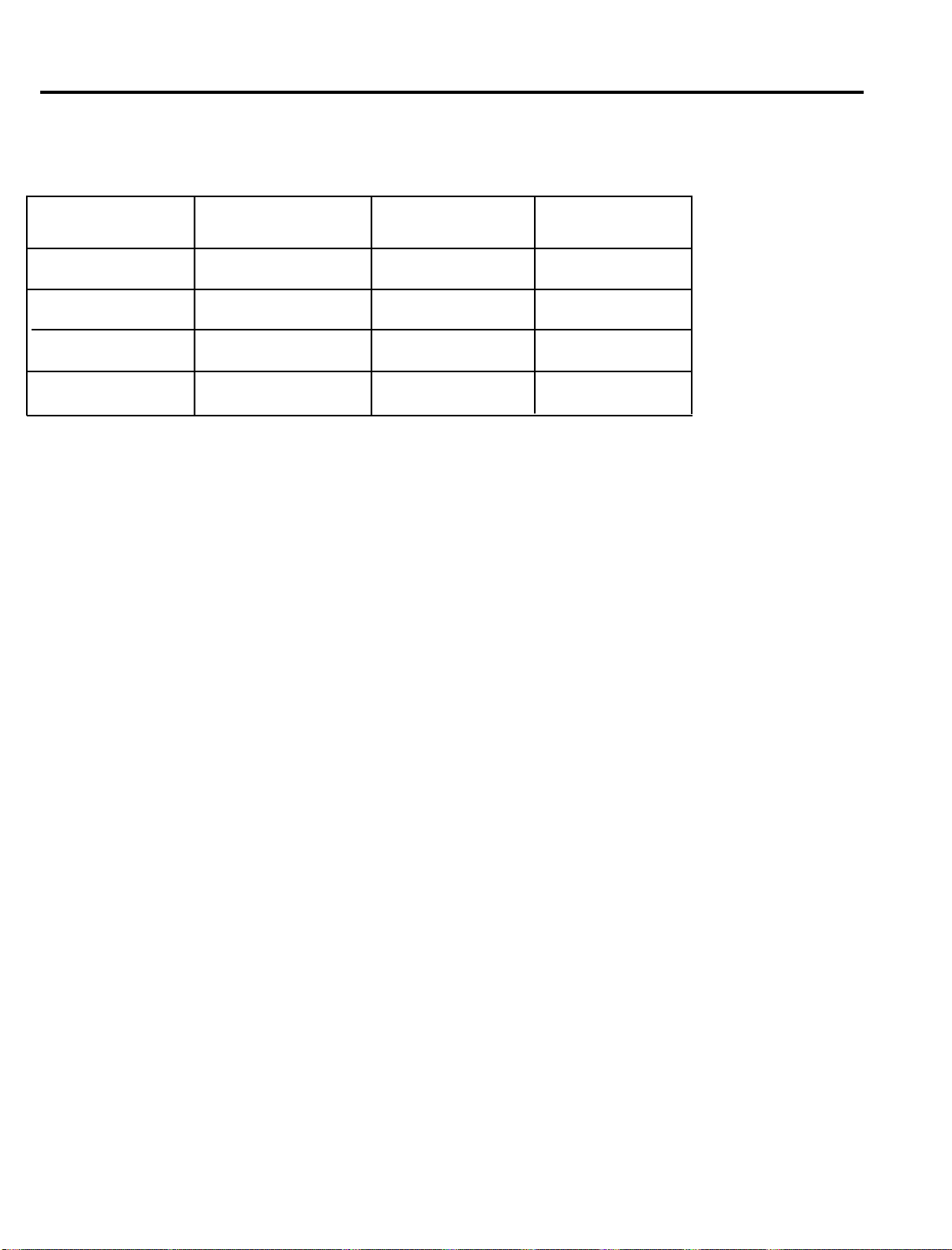
SAMPLE THREE STAGE PROGRAM
(Program with Cooling)
OPERATION
HEAT RATE
STAGE 1
STAGE 2
STAGE 3
STAGE 4
*Though any number may appear, the unit is deactivated when “NO” is selected for the HEAT RATE.
To start immediately, press START / STOP.
Follow the same programming procedures if a three or four stage program is desired.
Press NIGHT TIME (DELAY START) to start an overnight burnout. (See SAMPLE ON STAGE PROGRAM to
program NIGHT TIME (DELAY START) time.
NOTE: When the temperature is set to a lower temperature than in the previous stage,
the furnace ignores the programmed HEAT RATE (except for "NO") and
automatically cools to the pre-set temperature. The time required for the cooling
stage is determined by the pre-set temperature. The lower the temperature,
the more time needed to cool down.
10°F (6°C)
20°F (11°C)
NO
NO
TEMP
600°F (316°C)
1600°F (871°C)
*
*
HOLD TIME
30
1:00
*
*
16
Page 18
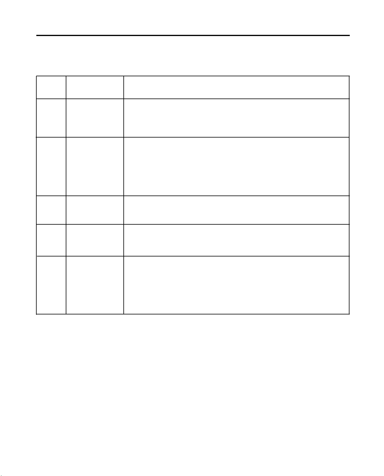
ERROR CODES
NOTE: “Beeps” occur when the Error Code appears on the Main Display
ERROR
CODE
Er 1
Er 2
Er 3
Er 4
DESCRIPTION
INVALID ENTRY
ERROR: STAGE,
HEAT RATE and
TEMP lights flash
TABLET
TEMPERATURE
CALIBRATION
ERROR
ELECTRONICS
MALFUNCTION
OPEN
THERMOCOUPLE
PROBABLE CAUSE
Occurs when the HEAT RATE is set to COOL but the TEMP of that stage is
higher than the TEMP of the prior stage (should be heating). This will occur
when a program is already running and a parameter was edited in process.
Occurs when the temperature on the display is outside the allowable range
at the time the user pressed the ENTER / REVIEW keys simultaneously to set
the Infinity calibration temperature to 1500°F. If this occurs and is not an
operator error, it indicates that there is a problem with the thermocouple or
the PC board. Press ENTER / REVIEW to turn off the error indication and
continue with the program. Press START / STOP to end the program.
Occurs when PC board hardware malfunctions.
Occurs if the thermocouple is open or the connecting wire(s) are broken or
disconnected from the terminal board.
Er 5
REVERSED
THERMOCOUPLE
Occurs if the thermocouple extension wires have been connected backwards
to the terminals on the printed circuit board. The error will be detected 5
minutes after heating program started. This error will also occur if the
program is started and the chamber door is kept open for 5 minutes or the
triac is defective, the heater plates are defective or there is a problem with
the main PC board.
17
Page 19
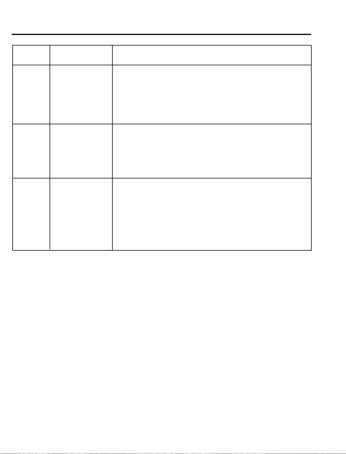
ERROR CODES
ERROR
CODE
Er 6
Er 7
Flashing
99:99 when
NIGHT
TIME
(DELAY
START) is
pressed
during a
program
DESCRIPTION
SHORTED
THERMOCOUPLE
OR DEFECTIVE
HEATER PLATES
THERMAL
RUNAWAY
INVALID ENTRY
ERROR WHILE A
PROGRAM IS
RUNNING
PROBABLE CAUSE
Occurs if the thermocouple wires are shorted or the heater plates are
defective causing Infinity to achieve a HEAT RATE of less than 6% of the
maximum attainable HEAT RATE with full power applied to the heater
plates for 5 minutes. This error will also occur if a program is running
and the door is kept open for more than 5 minutes or the triac or the
Main PC board developed a problem during a burnout process.
Occurs when the temperature has exceeded 2015°F (1102°C) for 1
minute if the highest temperature programmed was less than 2000°F
(1093°C). This also occurs when the temperature has exceeded
2050°F (1121°C) for 1 minute if the highest temperature programmed
was 2000°F (1093°C) or higher.
Occurs when the HEAT RATE in STAGE 2, 3 or 4 is set to “COOL” but
the corresponding TEMP is entered to heat to a higher temperature
than the previous stage.
18
Page 20
SERVICE
CAUTION: The INFINITY should be serviced only by qualified service technicians. Be sure to
unplug the power cord and wait for the furnace to cool before performing any service operation. For help with operating or servicing your Jelrus equipment, please call Whip Mix any
time between 8:00am and 5:00pm Eastern time.
Toll Free:
TEMPERATURE CALIBRATION
Infinity Multi–Stage Burnout Furnaces come complete with temperature Calibration Tablets (2) which accurately
melt at 1500°F (816°C). (Re–Order Calibration Tablet Kit – PN 15291).
Your Infinity is factory calibrated. It is not necessary to re-calibrate on installation. If it becomes necessary to
re-calibrate in the future, use the following calibration procedure.
Temperature Calibration with Calibration Tablets (Figure 3)
1. Place a short metal casting ring towards the front center of the chamber.
2. Place a ceramic tray or a small piece of casting ring lining material on top of the ring. Place a tablet
in the center of the tray.
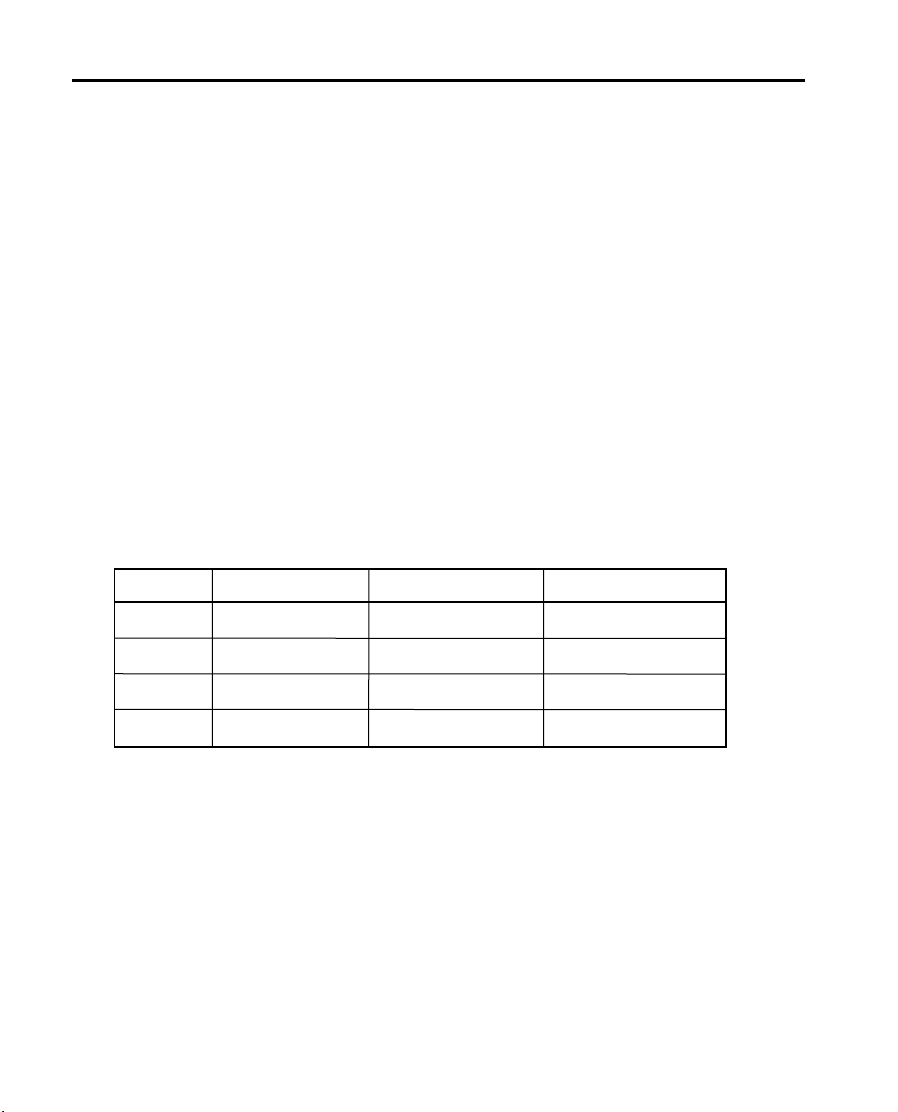
3. Program the Infinity as follows:
HEAT RATE TEMP HOLD TIME
STAGE 1 FULL 1200°F (649°C) 0:05
STAGE 2 25°F (14°C) 1700°F (927°C) 0:00
STAGE 3 NO * *
1–800–626–5651
POWER FAILURE
1. If a power failure occurs, the Infinity memorizes the conditions prior to the loss of power. When the power
returns, the Infinity returns to the proper point in the program.
2. When power is returned, the HR:MIN light flashes indicating that a power failure has occurred. It
continues to flash until START / STOP is pressed.
NOTE: The HR:MIN light flashes if the power switch is turned off and on while a
program is running and START / STOP was not pressed. It will not flash if the
power switch was turned off or a power failure occurred when the PROGRAM
READY light was on.
STAGE 4 NO * *
*Though any number may appear, the unit is deativated when “NO” is selected for HEAT RATE.
4. Close the furnace door and press START / STOP.
5. When the furnace temperature attains 1400°F (760°C) as indicated on the Main display, open the
furnace door slightly and begin to check for the melting of the of the tablet. Continue to do this at each
25°F (14°C) interval, opening the furnace door just enough to determine at a quick glance if the
tablet has begun to liquify at the edges.
19
REPLACEMENT OF DOOR INSULATION AND SPRINGS
Infinity M–30 – PN 15722 Door Insulation
Infinity L–30 – PN 15712 Door Insulation
Infinity M–30 and L30 – PN 33997 Door Spring and Hook Assembly Kit
1. Open, locate and remove the two screws on the door closest to the door hinges which hold the retainer
strip in place. Remove the retainer strip.
2. Remove the one piece door insulation by sliding it toward the rear of the furnace and slightly lifting.
3. To replace the springs, remove each spring from the hook which holds it in place. Remove both the
hook and spring.
4. To reinstall the new door insulation or springs and hooks, reverse the above procedure. If installing
springs and hooks, add grease to junction of spring and hook and spring and hinge junction.
Page 21
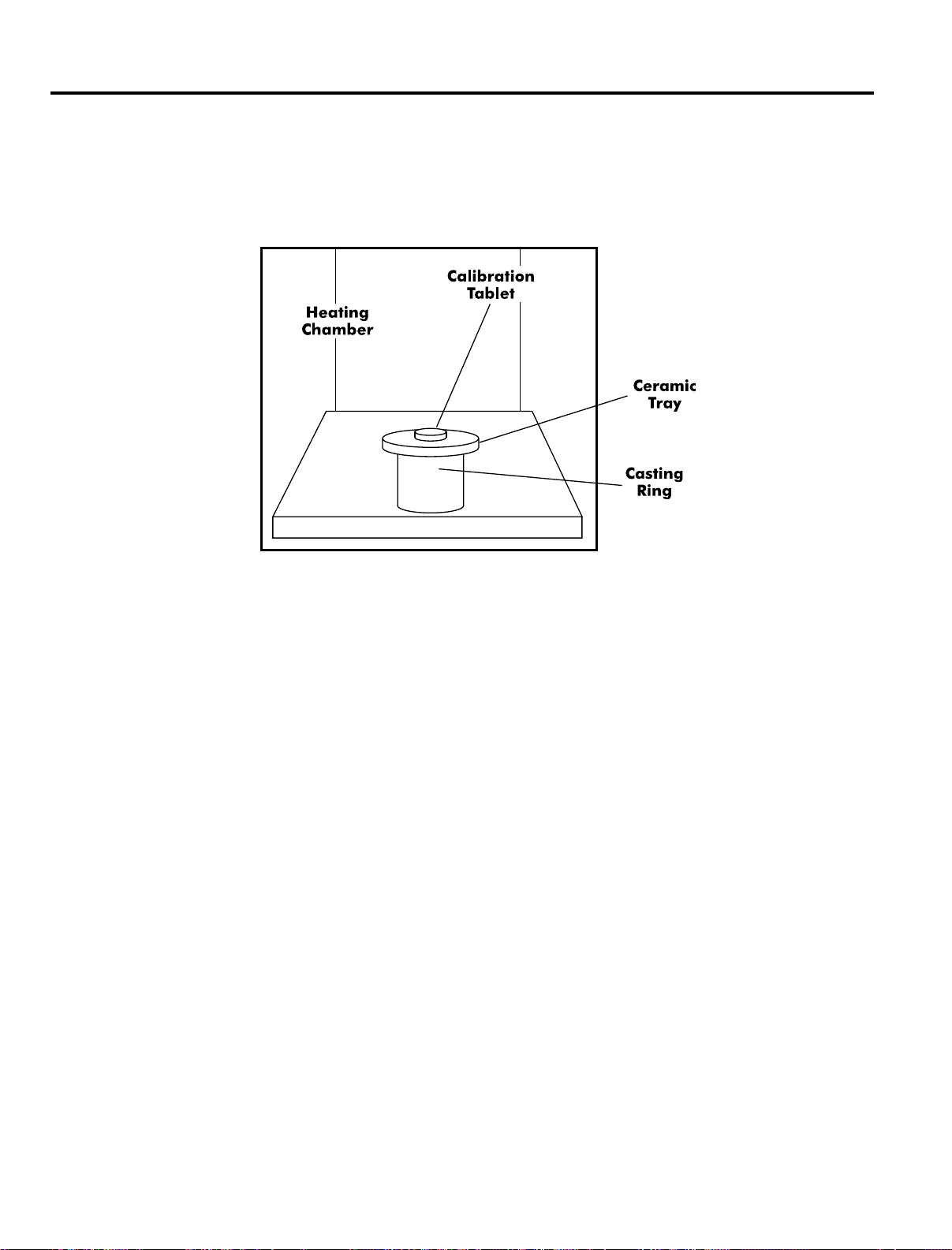
SERVICE
6. When the tablet begins to melt or liquify at the edges, immediately press and hold.
Then press ENTER/REVIEW. Your Infinity is now calibrated. Three “beeps” sound and
“CAL” appears on the main display.
POWER FAILURE
1. If a power failure occurs, the Infinity memorizes the conditions prior to the loss of power. When the power
returns, the Infinity returns to the proper point in the program.
2. When power is returned, the HR:MIN light flashes indicating that a power failure has occurred. It
continues to flash until START / STOP is pressed.
NOTE: The HR:MIN light flashes if the power switch is turned off and on while a
program is running and START / STOP was not pressed. It will not flash if the
power switch was turned off or a power failure occurred when the PROGRAM
READY light was on.
REPLACEMENT OF DOOR INSULATION AND SPRINGS
Infinity M–30 – PN 15722 Door Insulation
Infinity L–30 – PN 15712 Door Insulation
Infinity M–30 and L30 – PN 33997 Door Spring and Hook Assembly Kit
1. Open, locate and remove the two screws on the door closest to the door hinges which hold the retainer
strip in place. Remove the retainer strip.
2. Remove the one piece door insulation by sliding it toward the rear of the furnace and slightly lifting.
3. To replace the springs, remove each spring from the hook which holds it in place. Remove both the
hook and spring.
4. To reinstall the new door insulation or springs and hooks, reverse the above procedure. If installing
springs and hooks, add grease to junction of spring and hook and spring and hinge junction.
20
Page 22
FIELD SERVICE
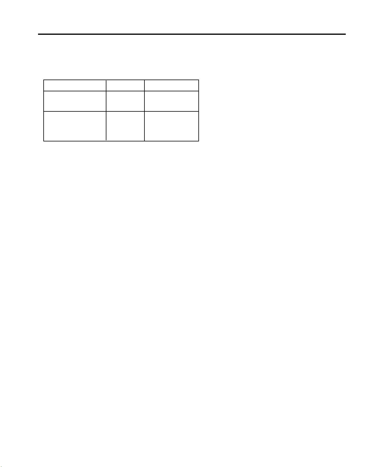
REPLACEMENT OF HEATING PLATES
REPLACEMENT PART NUMBERS
115V 220/230V
M–30 (Set of 2) 33915 33916
L–30
Set of 2 Side Plates 33918 27957
Set of 2 Rear Plates 33917 27956
1. Remove the back panel of the furnace.
2. Remove the nuts which hold the heating plate wires to the power terminals and straighten the heating
plate wires (Figure 4).
3. Open the furnace door and find the two ceramic sections at the front of the furnace chamber. Hold the
furnace door partially open while removing the ceramic sections. They are not readily removed when the
door is fully open. Remove the right–hand ceramic section by lifting it upward until the bottom of the section
clears the sheet metal housing. Pull the bottom of the ceramic section out, then pull it down so the upper
half clears the sheet metal housing. Remove the left–hand ceramic plate in the same way.
4. Remove the floor plate, then carefully slide the two side heating plates out the front of the furnace. The two
rear heating plates on Infinity L–30 may now be removed.
5. Check the condition of the filler strip insulation in the space to the left and right of the ceramic front
sections. Replace if required*.
6. Check the condition of the floor plate which provides insulation and serves as a spacer between the bottom
ends of the heating plates. Replace if required*.
7. To install the new heating plates reverse the procedure. Push the ceramic heating plates back into place on
the rear insulating panel. When reconnecting the heating plate wires at the rear of the furnace, be sure to
replace all hardware in its original position. (Figure 4.) Tighten all connections.
*Replacement Part: Floor Plate w/ Filler Strip Insulation
Infinity M–30: PN 33980; Infinity L–30: PN33981
21
Page 23
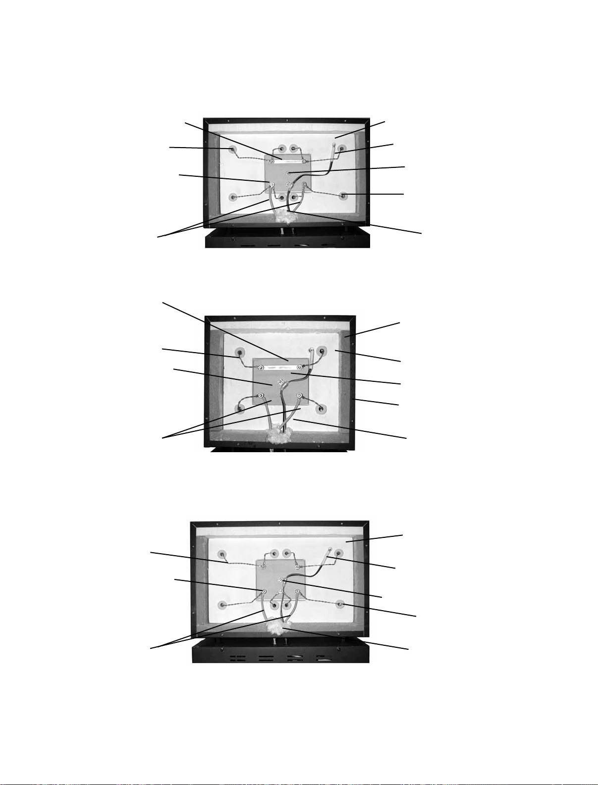
Figure 4
INFINITY WITH UPPER REAR PANEL REMOVED
Jumper
Heating Plate Wire
Power Terminal
Heater (Power) Leads
Jumper
Heating Plate Wire
Power Terminal
Rear Insulating Panel
Thermocouple
Thermocouple Clamp
Ceramic Insulating
Bushing
Insulating Filler
INFINITY M–30 (ALL VOLTAGES)
Rear Insulating Panel
Thermocouple
Thermocouple Clamp
Ceramic Insulating
Bushing
Heater (Power) Leads
Heating Plate Wire
Power Terminal
Heater (Power) Leads
Insulating Filler
INFINITY L–30 115 VOLT
Rear Insulating Panel
Thermocouple
Thermocouple Clamp
Ceramic Insulating
Bushing
Insulating Filler
INFINITY L–30 220/230 VOLT
22
Page 24

FIELD SERVICE
REPLACEMENT OF THE MAIN PC BOARD
REPLACEMENT PART NUMBERS
115V 220/230V
M–30 15500–041 15500–053
L–30 15500–541 15500–553
1. Remove the front panel (Figure 5).
2. Note and record the color and location of each wire on the thermocouple terminals located on the Main
PC Board. Remove both wires.
3. Remove the calibration jack connector (J1) from the Main PC Board by pulling straight up.
4. Remove five electrical connectors (BLACK, ORANGE, YELLOW, WHITE, GREEN) from the Main PC Board by
pulling straight up on the connector. DO NOT PULL ON THE WIRES.
5. Remove the nuts and lockwashers that hold the Main PC Board to the front panel and lift straight up to
remove board.
6. Align the holes in the new board with the standoffs on the front panel, reinstall the fasteners and screws.
7. Reconnect the electrical connectors as follows:
Black wire to terminal marked “H.” – E5.
Orange wire to terminal marked “GATE.” – E4.
Yellow wire to terminal marked “LOAD.” – E3.
White wire to terminal marked “N.” – E2.
Green wire to ground terminal. – E1.
8. Reconnect calibration jack connector. The green wire on the connector is closest to the bottom edge of the
front panel.
9. Reconnect the two thermocouple wires to the thermocouple terminals observing the color coding noted in
Step 2. If thermocouple wires are reversed, 5 minutes after heating program is started, "Er 5" will appear
on the Main Display.
10. Replace the front panel.
23
Page 25
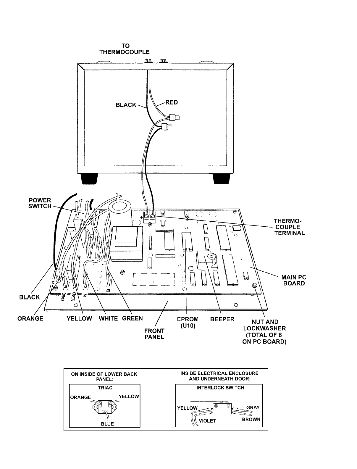
Figure 5
INFINITY WITH FRONT PANEL / MAIN PC BOARD REMOVED
Figure 5A
OTHER COMPONENTS
24
Page 26

FIELD SERVICE
REPLACEMENT OF THE THERMOCOUPLE ASSEMBLY (PN 18913)
1. Remove the bottom front panel and the upper and lower rear panels of the furnace. (Note the position of
the vent louvers on the rear panels.)
2. Note and record the color and location of the wires on the thermocouple terminals located on the Main
PC Board (Figure 5).
3. Remove the thermocouple wires from the thermocouple terminals on the Main PC Board (Figure 5).
4. Remove the clamp which secures the thermocouple to the ceramic terminal block located in the upper rear
of the furnace (Figure 4).
5. Remove the heating plate wire which crosses over the thermocouple and bend it out of the way just enough
to permit sliding the thermocouple out of the rear of the heating chamber (Figure 4).
6. Remove the insulating filler that covers the holes in the bottom of the upper section (Figure 4). Straighten
the thermocouple wires where they were bent at a 90° angle.
7. Withdraw the thermocouple down into the lower rear of the furnace through the holes in the upper and
lower sections. Discard thermocouple assembly.
8. Feed the new thermocouple from the lower rear of the furnace up through the holes in the upper and lower
sections and into the upper rear of the furnace.
1. Remove the lower rear panel (Figure 2).
2. Note and record the color and location of each of the three wires on the triac terminals
(Figure 5A). Remove each of the three wires by pulling straight up on the connector. DO NOT
PULL ON THE WIRES.
3. Remove the two nuts and screws that hold triac in place. Lift triac off the rear panel (Figure 5A).
4. There is an insulating pad located between triac and panel. If it did not come off with the triac,
remove it from the rear panel. Do not reuse. Wipe the rear panel to remove any grease-like materials.
5. Put the new insulating pad and then the new triac in place on the rear panel. Locate the triac
so that the center terminal will face downward when the rear panel is in place.
6. Replace the three wires on the triac terminals (Figure 5A) observing the following color coding:
Yellow wire to upper right terminal.
Blue wire to center (lower) terminal.
Orange wire to upper left terminal.
7. Replace the lower rear panel (Figure 2).
9. Bend the new thermocouple wires at a 90° angle approximately 3-3/8 inches (8.6cm) from the exposed
tip of the thermocouple. Be sure that there are three ceramic insulating sleeves between the thermocouple
tip and the bend. Insert the new thermocouple into the hole at the rear of the heating chamber.
10. Replace the heating plate wire that was removed in Step 3. Check that there is a ceramic insulating sleeve
covering the thermocouple wires where they cross the heating plate wire. Replace the clamp that holds the
thermocouple wires to the ceramic terminal block. Replace the insulating filler that covers the holes in the
bottom of the upper section.
11. Connect the thermocouple wires to the thermocouple terminals on the Main PC Board. Observe the color
coding you noted in Step 2.
12. Replace the front panel and the upper and lower rear panels. (Be sure the vent louvers on the rear panels
protrude out and face down.)
25
Page 27

FIELD SERVICE
REPLACEMENT OF THE TRIAC (PN 15475)
1. Remove the lower rear panel (Figure 2).
2. Note and record the color and location of each of the three wires on the triac terminals
(Figure 5A). Remove each of the three wires by pulling straight up on the connector. DO NOT
PULL ON THE WIRES.
3. Remove the two nuts and screws that hold triac in place. Lift triac off the rear panel (Figure 5A).
4. There is an insulating pad located between triac and panel. If it did not come off with the triac,
remove it from the rear panel. Do not reuse. Wipe the rear panel to remove any grease-like materials.
5. Put the new insulating pad and then the new triac in place on the rear panel. Locate the triac
so that the center terminal will face downward when the rear panel is in place.
6. Replace the three wires on the triac terminals (Figure 5A) observing the following color coding:
Yellow wire to upper right terminal.
Blue wire to center (lower) terminal.
Orange wire to upper left terminal.
7. Replace the lower rear panel (Figure 2).
26
Page 28

SPARE PARTS LIST
PARTS FOR INFINITY M–30
DESCRIPTION 115V 220/230V
Power Cord Kit–Japan & U.S. 15288 N/A
Power Cord Kit–Australia N/A 23206
Power Cord Kit–England N/A 23202
Power Cord Kit–Europe N/A 23203
Power Cord Kit–Italy N/A 23205
Main PC Board
Heater Jumper 33130 33130
Ceramic Front Section 15292 15292
Rear Insulating Panel w/ Block 33210 33210
Door Assembly 15284 15284
Door Insulation 15722 15722
Heating Plates Assembly Side (Set of 2) 33915 33916
Ceramic Terminal Block w/ Terminals 33935 33935
Upper Rear Panel Kit 33955 33955
Floor Plate w/ Filler Strip Insulation Kit 33980 33980
Door Handle Kit 15279 15279
Heating Chamber Insulation Kit 33982 33982
Thermocouple Assembly Kit 18913 18913
Triac Replacement Kit 15475 15475
Tray for Heating Chamber 33256 33256
Calibration Tablet Kit 1500
Interlock Switch Kit 15275 15275
Vent Tube 15729 15729
Ceramic Insulating Bushings (Pkg. of 4) 33958 33958
Mounting Feet (Set of 4) 15277 15277
Door Spring Hook Assembly Kit 33997 33997
Door Hinges (Set of 2) 33998 33998
Terminal Block (Rear Panel) 117387 117387
Circuit Breaker 117046 117047
Heater (Power) Leads (Set of 2) 33975 33975
Hinges (Set of 2) 33998 33998
o
F (816oC) 15291 15291
15500–041 15500–053
27
Page 29

PARTS FOR INFINITY L–30
DESCRIPTION 115V 220/230V
Power Cord Kit–Japan & U.S. 15289 N/A
Power Cord Kit–Australia N/A 23206
Power Cord Kit–England N/A 23202
Power Cord Kit–Europe N/A 23203
Power Cord Kit–Italy N/A 23205
Main PC Board 15500–541 15500–553
Heater Jumper 33130 N/A
Ceramic Front Section (Set of 2) 15293 15293
Rear Insulating Panel w/ Block 33710 33710
Door Assembly 15286 15286
Door Insulation 15712 15712
Heating Plate Assembly, Side (Set of 2) 33918 27957
Heating Plate Assembly, Rear (Set of 2) 33917 27956
Ceramic Terminal Block w/ Terminals 33936 33936
Upper Rear Panel Kit 339560 339560
Floor Plate w/ Filler Strip Insulation Kit 33981 33981
Heating Chamber Insulation Kit 33983 33983
Thermocouple Assembly Kit 18913 18913
Triac Replacement Kit 15475 15475
Tray for Heating Chamber 33256 33256
Power Switch 15684 15684
Calibration Tablet Kit 1500
Interlock Switch Kit 15275 15275
Vent Tube 15729 15729
Ceramic Insulating Bushings (Pkg. of 4) 33958 33958
Mounting Feet (Set of 4) 15277 15277
Door Spring Hook Assembly Kit 33997 33997
Door Hinges (Set of 2) 33998 33998
Terminal Block (Rear Panel) 117387 117387
o
F (816oC) 15291 15291
SPARE PARTS LIST
28
Page 30
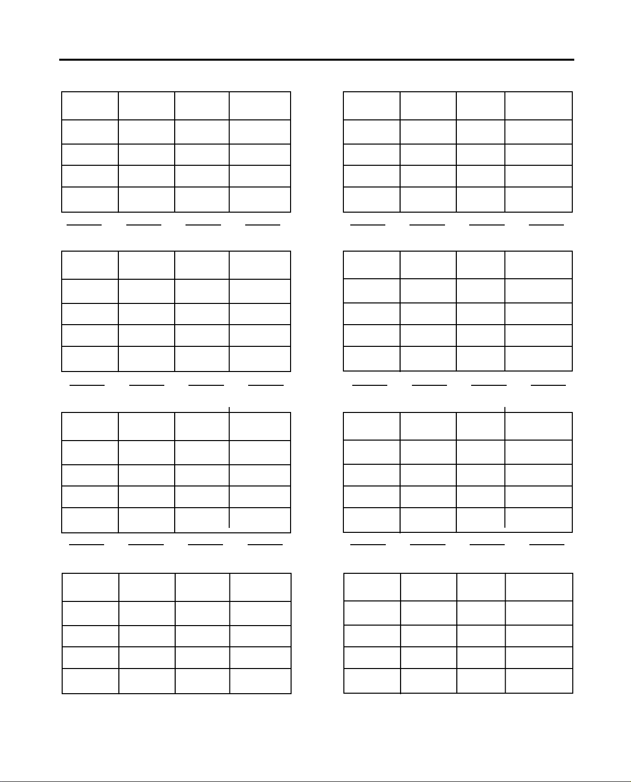
PROGRAM CARD FORMS
Program # Metal(s)
HEAT TEMP HOLD
RATE TIME
STAGE 1
STAGE 2
STAGE 3
STAGE 4
Program # Metal(s)
HEAT TEMP HOLD
RATE TIME
STAGE 1
STAGE 2
STAGE 3
STAGE 4
Program # Metal(s)
HEAT TEMP HOLD
RATE TIME
STAGE 1
STAGE 2
STAGE 3
STAGE 4
Program # Metal(s)
HEAT TEMP HOLD
RATE TIME
STAGE 1
STAGE 2
STAGE 3
STAGE 4
Program # Metal(s)
HEAT TEMP HOLD
RATE TIME
STAGE 1
STAGE 2
STAGE 3
STAGE 4
Program # Metal(s)
HEAT TEMP HOLD
RATE TIME
STAGE 1
STAGE 2
STAGE 3
STAGE 4
Program # Metal(s)
HEAT TEMP HOLD
RATE TIME
STAGE 1
STAGE 2
STAGE 3
STAGE 4
Program # Metal(s)
HEAT TEMP HOLD
RATE TIME
STAGE 1
STAGE 2
STAGE 3
STAGE 4
29
Page 31
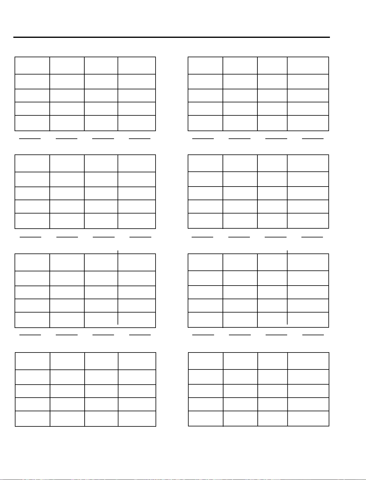
PROGRAM CARD FORMS
Program # Metal(s)
HEAT TEMP HOLD
RATE TIME
STAGE 1
STAGE 2
STAGE 3
STAGE 4
Program # Metal(s)
HEAT TEMP HOLD
RATE TIME
STAGE 1
STAGE 2
STAGE 3
STAGE 4
Program # Metal(s)
HEAT TEMP HOLD
RATE TIME
STAGE 1
STAGE 2
STAGE 3
STAGE 4
Program # Metal(s)
HEAT TEMP HOLD
RATE TIME
STAGE 1
STAGE 2
STAGE 3
STAGE 4
Program # Metal(s)
HEAT TEMP HOLD
RATE TIME
STAGE 1
STAGE 2
STAGE 3
STAGE 4
Program # Metal(s)
HEAT TEMP HOLD
RATE TIME
STAGE 1
STAGE 2
STAGE 3
STAGE 4
Program # Metal(s)
HEAT TEMP HOLD
RATE TIME
STAGE 1
STAGE 2
STAGE 3
STAGE 4
Program # Metal(s)
HEAT TEMP HOLD
RATE TIME
STAGE 1
STAGE 2
STAGE 3
STAGE 4
30
Page 32

1–800–626–5651
1–502–637–1451
www.whipmix.com
Infinity is a trademark of Whip Mix
©2011 Whip Mix®.
®
IJ15813 02/11
 Loading...