

Page 1

Page 2

USER MANUAL
MODEL M
320-00630-D
HF.DO-01 released 07/17
Page 3

USER MANUAL
MODEL M
Table of Contents!
1! Introduction .......................................................................................................................... 3!
! Welcome ........................................................................................................................ 3!
! Manual Overview ........................................................................................................... 3!
! Notations ........................................................................................................................ 3!
! Document Guidelines ..................................................................................................... 4!
! Illustrations............................................................................................................... 4!
! Product Specifications ............................................................................................. 4!
! Errors and Omissions .............................................................................................. 4!
! Intended Use .................................................................................................................. 4!
2! Safety ................................................................................................................................... 5!
! Warnings ........................................................................................................................ 5!
! Cautions ....................................................................................................................... 10!
3! Product ............................................................................................................................... 11!
! Model M Components .................................................................................................. 11!
! Arm and Seat Positions ................................................................................................ 12!
! Cushions ...................................................................................................................... 13!
! Specifications ............................................................................................................... 13!
! Dimensional Information .............................................................................................. 14!
! Test Information ........................................................................................................... 15!
4! Operation ........................................................................................................................... 16!
! Safety Check ................................................................................................................ 16!
! Transfers into and out of the chair ............................................................................... 17!
! Lap Belt ........................................................................................................................ 20!
! Power Switch ............................................................................................................... 21!
! Turning the Model M On ........................................................................................ 21!
! Turning the Model M off ......................................................................................... 22!
! Checking the Battery Charge Level ............................................................................. 22!
! Lights showing full battery charge ......................................................................... 22!
! Lights showing intermediate charge level .............................................................. 23!
! Low battery indication ............................................................................................ 23!
Page 4

USER MANUAL
MODEL M
! Speed Control .............................................................................................................. 24!
! Speed Setting ........................................................................................................ 24!
! Speed control through the directional controller .................................................... 25!
! Directional Controller .................................................................................................... 25!
! Safety Check when Starting to Move ........................................................................... 27!
! Driving Conditions ........................................................................................................ 28!
! Stopping and Parking ................................................................................................ 31!
! Sitting at a Table or Desk .......................................................................................... 31!
5! Brake Release Levers ........................................................................................................ 32!
! How to release the electromagnetic brakes ................................................................. 33!
! How to engage the electromagnetic brake(s) .............................................................. 34!
6! Battery and Charging ......................................................................................................... 35!
! Charger specifications for WHILL Model M .................................................................. 36!
! Charging the battery ..................................................................................................... 38!
! Battery service or replacement .................................................................................... 40!
7! Electromagnetic Interference (EMI) ................................................................................... 40!
! EMI Sources ................................................................................................................. 41!
! EMI Guidance Tables ................................................................................................... 41!
8! Troubleshooting ................................................................................................................. 46!
9! Maintenance ....................................................................................................................... 46!
10! Transport Option .............................................................................................................. 47!
! Using the Transport Option ....................................................................................... 49!
! Proper Occupant Restraint ....................................................................................... 52!
! Clear Zones .............................................................................................................. 54!
11! Symbols ........................................................................................................................... 56!
12! Warranty .......................................................................................................................... 59!
13! Customer Support ........................................................................................................... 60!
USER MANUAL
MODEL M
Page 59
12 Warranty
WHILL, Inc. (WHILL) personal mobility and wheelchair products (“Product”) are warrantied
against defects in materials and workmanship as follows, for a period from the date of your
receipt of the Product from WHILL or a WHILL-authorized third-party distributor or reseller
equal to the following: (i) with respect to the base and seat frame, five (5) years, and (ii) with
respect to the seat and back cushion, two (2) years, and (iii) with respect to the electrical and
mechanical components, one (1) years, and (iiii) with respect to the batteries and tires, six (6)
months (“Warranty Period”) in each case when used in accordance with the applicable usage
documentation. If a defect arises during the Warranty Period, WHILL will, at its option: (a)
provide replacement parts that are new and/or previously used parts that are equivalent to new
in performance and reliability to the defective parts or, with your consent, are at least
functionally equivalent to the parts they replace; or (b) exchange the affected Product with a
functionally equivalent Product that is new or formed from new and/or previously used parts
that are equivalent to in performance and reliability or, with your consent, a Product that is at
least functionally equivalent to the Product it replaces.
This warranty excludes: (i) normal depletion of consumable and/or wearable parts (such as
trim components and covers for the seat and back cushion) unless failure has occurred due to
a defect in materials or workmanship; and (ii) damage resulting from abuse, accident,
modifications, unauthorized repairs, or other causes that are not defects in materials and
workmanship.
Further this warranty does not cover any labor costs that may be incurred in connection with
installation or repair of your Product. The Product is sold primarily through third-party
distributors and/or resellers, which provide warranty repair services to WHILL customers, who
may or may not charge fees for their repair labor under separate terms and conditions. In the
event the distributor or reseller is no longer in business or has ceased to sell WHILL products,
WHILL will provide a list of authorized repair companies. Please contact WHILL to obtain a
current list of authorized repair companies.
This warranty is valid solely for customers who purchased their Product directly from WHILL or
a WHILL-authorized third-party distributor or reseller in the United States and Puerto Rico.
Some states and countries do not allow limitations on how long such warranties, conditions,
and/or implied terms may last, so the limitation described above may not apply to you. This
warranty is offered in addition to rights and remedies conveyed by consumer protection laws
and regulations that cannot be statutorily waived, and does not affect your applicable statutory
rights.
No person other than WHILL is authorized to modify this limited product warranty.
Page 5
USER MANUAL
MODEL M
Page 3
1 Introduction
Welcome
Welcome to your new WHILL device! The Model M has amazing features that we hope
will positively change the way you live your daily life.
The following items are provided to you:
• WHILL Model M powered wheelchair
• WHILL mobility device charger (High Power off-board battery charger)
• User Manual (printed or digital copy of this manual)
CAUTION
CAUTION: Federal (USA) law restricts this device to sale by or on the order of a
physician.
Manual Overview
This User Manual provides relevant guidelines for the WHILL Model M on how to safely
use important features of the device, such as the speed and directional controllers. It also
provides basic service, troubleshooting, and maintenance information.
The manual may also be used by dealers, resellers, sales people, and others who wish to
understand important features of the device in more detail.
At WHILL, we care about your safety and experience with our products. Please carefully
read and follow all the instructions in this manual.
Notations
WARNING
Indicates a hazardous situation that, if not avoided, could result in death or serious
injury.
Page 6

USER MANUAL
MODEL M
Page 4
CAUTION
Indicates a hazardous situation that, if not avoided, may result in property damage,
minor injury, or both.
INFORMATION
Gives useful tips, recommendations and information for efficient, trouble-free use.
Document Guidelines
INFORMATION
THE INFORMATION CONTAINED IN THIS DOCUMENT IS SUBJECT TO CHANGE
WITHOUT NOTICE.
Illustrations
The illustrations provided in this manual are for demonstration and conceptual
visualization purposes only. Your actual product might vary from the illustrations in
the following ways:
• The directional controller (joystick) may be on either the left or right arm.
• There are different shapes for the directional controller.
Product Specifications
All specifications and descriptions contained in this manual are verified to be
accurate at the time of printing.
Errors and Omissions
Please send an email to: support@whill.us if you notice any inaccuracies or
omissions in this manual.
Intended Use
The intended use of the WHILL powered wheelchair is to provide indoor and outdoor
mobility to persons limited to a seated position that are capable of operating a powered
wheelchair.
The chair supports a maximum weight of 220 lbs.
USER MANUAL
MODEL M
Page 57
Caution. Indicates the need for the user to consult the instructions
for use for important cautionary information such as warnings and
precautions not presented on the medical device itself.
Consult Instructions for Use
CAUTION: Federal (USA) law restricts this device to sale by or on
the order of a physician.
Dispose of this equipment according to local regulations for
electrical and electronic waste disposal
Brake release is locked
Brake release is unlocked
Indoor use only
IEC 61140 Class II electrical appliance. The product is double
insulated and does not require a safety connection to electrical
earth.
Temperature limits within which the shipping package shall be
stored and handled
Humidity limits within which the transport package shall be stored
and handled
Page 7

USER MANUAL
MODEL M
Page 5
2 Safety
Warnings
WARNING
Model M operation
• Do not operate the Model M without first reading this user manual. Please pay close
attention to all safety information and warnings. Contact customer support if you
need any clarification on sections that are unclear. Failure to read and understand
how to properly operate the Model M may result in damage and/or injury.
• The weight capacity of the Model M is 220 lbs. To avoid injury or Model M failure,
do not exceed this weight.
• Do not operate the Model M if the battery is depleted as you could be stranded.
• Do not use the device if there are broken components as you could be injured by
sharp edges or exposure to moving parts.
• Do not operate the Model M on any streets, roads, or highways. Operating the
Model M on streets, roads, or highways may expose you to situations that may result
in severe damage and/or injury. Before crossing the street, make sure that any and
all drivers see you.
• Do not use the Model M if it has been exposed to excessive water, is damaged in
any way, or requires service. Contact WHILL or reseller for service.
• To prevent injury and/or damage, do not use the Model M in heavy snow or icy
conditions. The Model M is not designed for use in these types of conditions.
• Do not drive the Model M through water deeper than 1”. Doing so may damage the
components and make the Model M inoperable.
• Do not operate the Model M on soft surfaces such as sand or mud. Doing so may
cause you to become stuck and unable to move the Model M.
• Do not use the Model M on slopes greater than 17% as the device may become
unstable and tip over, resulting in damage and/or injury. The Model M has been
tested for stability on 17% slopes (10 degrees) and should only be used on slopes
less than 17%. For reference, a standard ramp with a railing going into a public
building has an 8.3% slope.
• Do not use the Model M to navigate objects taller than 3”. Doing so may cause the
device to become unstable and tip over, resulting in damage and/or injury. The
Model M is designed and tested for stability on obstacles less than 3” in height.
• Use extreme caution when driving on uneven surfaces or slopes. In these conditions
the device may become unstable and tip over, resulting in damage and/or injury. It
Page 8

USER MANUAL
MODEL M
Page 6
is recommended that you have someone available to stabilize the Model M if
necessary when driving on uneven or sloped surfaces.
• Do not use the Model M as a seat during weight training. Doing so may cause the
device to become unstable and tip over, resulting in damage and/or injury. The
Model M is not intended to be used as a seat during weight training.
• For your safety, always fasten the lap belt when you are in the Model M. Failure to
fasten the lap belt over your lap could result in injury if something occurs that causes
you fall out of the chair.
• Only use seat cushions that have been certified to pass flammability testing.
• Do not change the seat cushions in the device without having your positioning
evaluated by a seating technician. Failure to do so may result in injury due to
improper positioning.
• To prevent injury to your legs or knees, you should inspect underneath tables or
other objects before sliding the seat forward. Failure to do so may result in injury due
to hitting objects with your legs or knees.
• Check that the tail lamps are working properly before operating the Model M at night
or in low visibility conditions. Failure to check the tail lamps could result in injury if
others cannot see the chair and collide with it.
• It is not safe to operate the Model M with the footplate in an up (vertical) position.
Make sure the footplate is down before moving.
• Make sure your hands, arms, elbows and feet are inside the Model M when moving.
• Stopping distance on slopes can be significantly greater than on level ground.
Brake lock release
• Only disengage the brake locks (put the Model M in freewheel mode) for emergency
and short-term use only. When the brake locks are released, the chair movement
can only be stopped by external forces (a person or object). Failure to engage the
brake locks may result in damage and/or injury if the chair moves uncontrollably.
• To prevent unintended movement, the Model M should be powered off whenever the
brake locks are being engaged or disengaged. Failure to turn the power off may
result in accidental chair movement, resulting in a collision and possible damage
and/or injury.
• Do not use the Model M on a slope when the brake locks are disengaged (in
freewheel mode). When the brake locks are released, the chair movement can only
be stopped by external forces (a person or object). Failure to engage the brake
locks when on a slope will make it extremely difficult to control or stop the Model M
movement and could result in serious injury.
USER MANUAL
MODEL M
Page 55
Figure 35. Side view of recommended front and rear clear zones (numbers in inches)
The seated head height is estimated to range from 47” for a small adult female to 61” for a
tall adult male.
The following warnings are related to clearance zones:
WARNING
• Only forward-facing use of the wheelchair in a motor vehicle is allowed.
• Sufficient forward and rearward clear space should be provided around the
wheelchair occupant (Figure 34 and Figure 35). The FCZ must be larger when a
shoulder-belt restraint is not used.
• Vehicle interior components that cannot be removed from the clear zones or that are
near the occupant’s space at a level that may come in contact with the occupant’s
head during a side-impact collision or vehicle roller, should be padded with a
material that complies with Federal Motor Vehicle Safety Standard 201.
It is strongly recommended that both pelvic and shoulder belts be used by the wheelchair
occupant.
Page 9

USER MANUAL
MODEL M
Page 7
Service
• The Model M contains no user-serviceable parts. Do not attempt to replace or repair
any parts (including the batteries) on your own. Doing so may result in damage
and/or injury. Service should only be done by a WHILL-authorized service
representative.
• Do not spray water to clean off the Model M. Moisture may damage Model M
components and make it inoperable.
• Do not attempt to adjust or modify the Model M. Doing so may damage the Model
M. Adjusting or modifying the Model M may also make it less stable or impact its
performance, resulting in injury if the chair tips over or is not controllable.
Transportation
If your device is not equipped with securement points for transportation:
• Do not let anyone sit in the wheelchair while in a moving vehicle.
• Transfer to the vehicle seat and use the vehicle-installed occupant restraint system.
• Make sure the brake releases are locked and secure the wheelchair so that it cannot
roll or shift.
• Do not transport the wheelchair in the front seat of a vehicle. If it moves or shifts it
can interfere with the driver.
• Any wheelchair that has been involved in a motor vehicle accident should not be
used until inspected and tested by WHILL authorized service personnel. The
structure or the wheelchair could be compromised or components broken that could
make the wheelchair unsafe to operate or could otherwise injure you.
If your device has securement points:
• Please contact WHILL customer support with questions about using the wheelchair
as a seat in a motor vehicle.
• The wheelchair must only be transported in a vehicle that is approved for such
purposes.
• Only forward-facing use of the wheelchair in a motor vehicle is allowed.
• Only use the wheelchair in a motor vehicle as described in these instructions.
• Dynamic testing was conducted in a forward-facing wheelchair with a 172 lb crash
test dummy restrained by both pelvic and shoulder belts. Both pelvic and shoulder
belts should be used to reduce the possibility of head and chest impacts with vehicle
components.
• Do not make any alterations to the wheelchair frame components or parts as these
can compromise the device’s transportability.
• Make sure the brake releases are locked and secure the wheelchair so that it cannot
roll or shift
Page 10

USER MANUAL
MODEL M
Page 8
• The lap belt is not designed for use as an occupant restraint when riding in a motor
vehicle. To prevent damage and/or injury, you must use approved vehicle-anchored
WTORS pelvic and shoulder belts. The lap belt present on the wheelchair may be
used in addition to the vehicle-anchored occupant restraints as long as it does not
interfere with the proper positioning of the WTORS.
• Both pelvic and shoulder belt restraints that comply with RESNA WC-4 Section 18,
Wheelchair Tie-down and Occupant Restraint Systems For Use in Motor Vehicles
should be used to limit occupant movement in a crash and reduce the likelihood of
injury
• The WTORS that are used to secure the wheelchair to the vehicle and you to the
vehicle (the occupant restraints) must be installed and attached in accordance with
the manufacturer’s instructions and RESNA WC-4 Section 18, Wheelchair Tie-down
and Occupant Restraint Systems For Use in Motor Vehicles.
• Attach the WTORS only to the designated securement points on the wheelchair. Do
not connect the WTORS to any other part of the wheelchair. Doing so may result in
structural damage to the wheelchair.
• Attach the occupant restraints following the manufacturer’s instructions and RESNA
WC-4 Section 18, Wheelchair Tie-down and Occupant Restraint Systems For Use in
Motor Vehicles.
• Any wheelchair-mounted accessories should be removed during transport and
secured separately in order to reduce the chance they will break loose and injure
vehicle occupants
• Sudden stops or motor vehicle accidents may damage your wheelchair. Do not
used the wheelchair until inspected and tested by WHILL authorized service
personnel. The structure or the wheelchair could be compromised or components
broken that could make the wheelchair unsafe to operate or could otherwise injure
you.
• Sufficient forward and rearward clear space should be provided around the
wheelchair occupant. The forward clear zone must be larger when a shoulder-belt
restraint is not used.
• Vehicle interior components that cannot be removed from the clear zones or that are
near the occupant’s space at a level that may come in contact with the occupant’s
head during a side-impact collision or vehicle roller, should be padded with a
material that complies with Federal Motor Vehicle Safety Standard 201.
Battery Charging
• Read the instructions before attempting to use the battery charger.
• Only use the original battery charger provided with the Model M. Use of any other
charger may cause damage or injury and will void the product’s warranty. Please
contact customer support if you need a replacement battery charger.
USER MANUAL
MODEL M
Page 53
For proper positioning:
• Belt restraints should not be routed outside of the wheelchair or over the wheelchair
arm supports and should not be held away from the body by wheelchair components
or parts (Figure 32).
• The belt restraint buckle of three-point belt restraints must be placed in contact with
the occupant’s body and away from wheelchair components.
• Upper-torso belt restraints should fit directly over, and be in contact with the middle
of the shoulder (Figure 33).
• The junction of the shoulder belt and pelvic belt of three-point belts should be
located near the hip opposite to the shoulder over which the diagonal belt crosses
and not near the midline of the occupant.
• Belt restraints should be adjusted as snugly as possible, consistent with user
comfort.
• Belt restraints should not be worn or twisted in a manner that reduces the area of
contact of the belt webbing with the occupant.
Figure 32. Do not place the belt restraints on the outside of the arms or wheels
Page 11

USER MANUAL
MODEL M
Page 9
• Battery charging should only be performed indoors. Exposing the battery charger to
any moisture, water, or other elements may result in fire or electric shock.
• To reduce the risk of fire or electric shock, do not use extension cords with the
battery charger. Use of extension cords may result in damage and/or injury.
• To reduce the risk of fire or electrical shock, do not leave the Model M plugged in
and continuously charging for more than one week. Extended charging of the Model
M may result in damage and/or injury.
• Keep the wheelchair and battery charger away from sources of ignition, such as
flames and sparks, because the battery can generate explosive gasses while
charging.
• Carry out charging with the wheelchair in a space at least twice its volume, with
sufficient ventilation that there is no hazard due to build-up of flammable gas.
• Do not use the battery charger to charge other batteries.
• Do not carry the battery charger on the wheelchair.
Electromagnetic Interference
• Electromagnetic Interference (EMI) from external sources can impact braking and
control of the Model M. Unintended brake release or Model M movement could
result in serious injury. To prevent this:
o DO NOT operate hand-held transceivers (transmitters/receivers), such as
citizens band (CB) radios, or turn ON personal communication devices, such
as cellular phones, while the powered Model M is turned ON;
o Be aware of nearby transmitters, such as radio or TV stations, and try to
avoid coming close to them;
o If unintended movement or brake release occurs, turn the Model M OFF as
soon as it is safe;
o Be aware that adding accessories or components, or modifying the powered
Model M, may make it more susceptible to EMI;
o Report all incidents of unintended movement or brake release to the powered
Model M manufacturer, and note whether there is a source of EMI nearby.
Section 6 of this user manual contains more information on EMI and how it can
affect the Model M. To properly understand EMI, please read Section 6.
Page 12

USER MANUAL
MODEL M
Page 10
CAUTION
Cautions
• Be sure to fully charge the batteries before any initial use of the Model M. Failure to
charge the new batteries may reduce the overall battery life.
• To prevent the batteries from draining completely, charge the Model M at least once
per month. If the batteries drain completely, do not use the Model M and have the
batteries replaced as soon as possible.
• Be sure to check behind you for loose clothing or other material before moving the
seat backwards. Failure to do so may result in items becoming caught in the seat
slide rails. Gather up any objects and move them out of the way to ensure no
damage is caused by seat movement.
• Reaching or leaning can affect the stability and balance of the Model M. To prevent
injury, always exercise caution when shifting your weight or balance in the Model M.
When in doubt, ask for help when reaching for inaccessible objects.
• The rear horizontal metal bar is available for you carry loads. Be sure that your
weight plus the weight of the load does not exceed the wheelchair capacity. Also, be
aware that carrying a heavy load may cause instability and harm.
• Removal of the rear access cover and extended exposure of the electrical parts and
batteries underneath may cause serious damage to the wheelchair.
• To avoid injuries when the seat is backing up, do not stand on the seat slide track
that is exposed when the seat is forward.
• Exercise caution when touching the omni wheels to avoid being pinched by the
rollers.
• Do not park the wheelchair near external sources of heat that may harm the user or
damage the wheelchair. Surface temperatures of the wheelchair can increase or
decrease when exposed to external sources of heat or cold.
USER MANUAL
MODEL M
Page 51
Figure 29. Front tie down point
Each tie down is identified with the hook gage symbol:
Figure 30. Tie down point marking
Page 13

USER MANUAL
MODEL M
Page 11
3 Product
Model M Components
Figure 1. Model M Components
Page 14

USER MANUAL
MODEL M
Page 12
Table 1. Components as Labeled in Figure 1
a
Back Support Cushion
b
Directional Controller
c
Arm
d
Pressure relief handles
e
Seat Cushion
f
Foot Support
g
All Directional Wheel
h
Arm Support
i
Tail Lamp
j
Rear Tire
k
Mode Switch
l
Battery Indicator
m
Charger Port
n
Brake Release Lever
Arm and Seat Positions
The Model M arms and seat can each be in two different positions (Figure 2).
Arm Down/Seat Back
Position
Arm Down/Seat Forward
Position
Arm Up/Seat Forward
Position
To drive the Model M, the arms
must be locked in the down
position and the seat moved all
the way back
Creates space to free your arms
and allow for easier transfers
Allows you to get closer to the
edge of a table
Transfer is easier with the seat
positioned forward
Figure 2. Model M Seat and Arm Positions
USER MANUAL
MODEL M
Page 49
• Do not transport the wheelchair in the front seat of a vehicle. If it moves or shifts it can
interfere with the driver.
• Any wheelchair that has been involved in a motor vehicle accident should not be used
until inspected and tested by WHILL authorized service personnel. The structure or the
wheelchair could be compromised or components broken that could make the
wheelchair unsafe to operate or could otherwise injure you.
Using the Transport Option
This section only applies to wheelchairs that have the optional tie downs installed. If the
transport symbol is present on the wheelchair the four tie downs have been installed on
the device and it can be used as a seat in a vehicle. In the descriptions that follow, the
person in the wheelchair in a vehicle is referred to as the “occupant”.
NOTE: WHILL does not offer Wheelchair Tie-down and Occupant Restraint Systems
(WTORS). You should purchase WTORS that are compliant with RESNA WC-4 Section
18, Wheelchair Tie-down and Occupant Restraint Systems For Use in Motor Vehicles
from your wheelchair distributor.
The following warnings apply:
WARNING
• Please contact WHILL customer support with questions about using the wheelchair as a
seat in a motor vehicle.
• The wheelchair must only be transported in a vehicle that is approved for such
purposes.
• Only forward-facing use of the wheelchair in a motor vehicle is allowed.
• Only use the wheelchair in a motor vehicle as described in these instructions.
• Dynamic testing was conducted in a forward-facing wheelchair with a 172 lb crash test
dummy restrained by both pelvic and shoulder belts. Both pelvic and shoulder belts
should be used to reduce the possibility of head and chest impacts with vehicle
components.
• Make sure the brake releases are locked and secure the wheelchair so that it cannot roll
or shift
• Do not make any alterations to the wheelchair frame components or parts as these can
compromise the device’s transportability.
• The lap belt is not designed for use as an occupant restraint when riding in a motor
vehicle. To prevent damage and/or injury, you must use approved vehicle-anchored
WTORS pelvic and shoulder belts. The lap belt present on the wheelchair may be used
Page 15

USER MANUAL
MODEL M
Page 13
Cushions
The WHILL Model M is provided with a seat cushion. The seat base is compatible with
seat cushions 16” wide and from 16” to 20” long. Please refer to the instruction manual
provided with your cushion for warnings, maintenance, and use of the seat cushions.
WARNING
• Only use seat cushions that have been certified to pass flammability testing.
• Do not change the seat cushions in the device without having your positioning
evaluated by a seating technician. Failure to do so may result in injury due to
improper positioning.
Specifications
There is only one model of the Model M wheelchair, the specifications are listed below.
Table 2. Model M Specifications
Item
Specification
Drive System
4 Wheel Drive
Controller
WHILL Controlling System
Seat Sliding Range
5.9" (150mm)
Chair Ground Clearance
3.5" (89mm)
Maximum Speed
5.5 MPH (8.9 km/h)
Speed Settings
Fast, Medium, Slow Speed
Braking System
Electromagnetic Brake
Turning Radius
28" (711mm)
Maximum Weight Capacity
220lb (100kg)
Arm Angle (down position)
45, 48, 52, 56 degrees
Tail lamps (2)
Red lights
Batteries (2)
12V 50Ah (per battery)
Charger
6A_Charger
Charging time: 8 hours to 80% charge
Foot Support Angle
0 to 10 degrees
Foot Support Extension
0”, 1", 2", 3", 4" (0 mm, 25mm, 50mm,
75mm, 100mm)
Compatible Back Supports
VARILITE Icon back system - Low, Mid,
Tall, Deep
Page 16

USER MANUAL
MODEL M
Page 14
Item
Specification
Compatible Seat Cushions
16" wide, from 16” to 20” deep
Operating Conditions
-13 to 122 degrees F (-25 to 50 degrees C)
Storage Conditions
-40 to 149 degrees F (-40 to 65 degrees C)
Dimensional Information
The RESNA standard (Section 15) requires disclosure of specification information in the
format listed below.
Table 3. Model M Dimension
Item
Specification
Overall length
43” (1092mm) without feet
44.3” (1126mm) with feet
Overall width
23.7" (602mm)
Total mass (including batteries)
255 lb (115.7kg)
Pivot width
44.4” (1128mm) without feet
45.7” (1161mm) with feet
Required width of right angled
corridor
35” (889mm) without feet
36.3” (922mm) with feet
Seat plane angle
4 to 14 degrees (4 positions)
Effective seat depth
16” to 20" (406.4 to 508mm) (5
positions)
Effective seat width
16” (406.4mm)
Seat surface height at front edge
20.2” to 22.2" (513.1 to 563.9mm) (3
positions)
Back support angle
10 to 20 degrees (4 positions)
Back support height
20” (508mm)
Foot support to seat
8.6” to 16.9” (218 to 429mm) (5
positions)
Leg to seat surface angle
104 degrees
Arm support height
8.5” to 10.5” (215 to 265mm) (6
positions)
Front location of arm support
structure
10” (254mm)
Propelling wheel diameter and size
including width
Diameter: 12.6” (320mm)
Width: 2.25” (57.1mm)
USER MANUAL
MODEL M
Page 47
It is recommended that users take the Model M to a WHILL-authorized reseller or WHILL-
authorized service technician for an annual safety inspection of the device
including general wear and tear of seating and tires.
10 Transport Option
Determine if your wheelchair has the optional tie downs (securement points) installed. To
do this, look for the transportation symbol (Figure 27) on the back of the device, below the
seat (Figure 28).
Figure 27. RESNA WC-4 Section 19 transportation symbol
The symbol indicates that the wheelchair has been tested for transportability and is in
compliance with RESNA WC-4 Section 19, Wheelchairs used as seats in motor vehicles.
Page 17

USER MANUAL
MODEL M
Page 15
Item
Specification
Horizontal location of axle
3” (75mm)
Static, impact and fatigue testing
requirements
Pass
Resistance to ignition
Pass
Test Information
The RESNA standard (Section 15) requires disclosure of the performance test results.
Some of the testing required the use of a test dummy. In all cases, the test dummy
used weighed 220 lbs. The test methods used were as specified in RESNA WC-1
Section 15. The test data are summarized below
Table 4. Model M Performance Values
Test
Value
Static stability forward – drive wheels locked
16.3○ (lock-out)
>20○ (full speed)
Static stability rearward – drive wheels locked
16.8○ (full speed)
Static stability anti-tip – drive wheels locked
17.6○ (full speed)
Maximum slope on which the chair remains upright
after testing during all applicable tests
10○
Maximum step/transition height across which
wheelchair remains stable during all applicable tests
80.0 mm (3.1 in)
Running brakes – forward-reverse command
stopping distance on level
57” (1448mm)
Continuous theoretical driving range
15.12 miles (24.33
km)
Maneuvering theoretical driving range
5.42 miles (8.72 km)
Maximum speed forward – horizontal surface
5.75 mph (2.57 m/s)
Maximum speed forward - 10○ inclined plane
(maximum safe slope)
3.87 mph (1.73 m/s)
Climatic testing – rain, hot and cold operation and
storage – pass/fail
Pass
Maximum obstacle height the chair can both climb
and descend with technique used
3.1” (80.0mm): climb
forward with run-up,
descend casters
trailing
Electrical systems – meets all requirements
Pass
Page 18

USER MANUAL
MODEL M
Page 16
Test
Value
Maximum thermal drive test results – total distance
traveled uphill and reason for stopping test
1148.3 ft (350.0m)
(chair drove for 60
minutes)
Non-powered mobility test – force required to start
the loaded wheelchair moving in a straight line on
the horizontal without electrical power
98N
Electromagnetic compatibility
Pass
4 Operation
WARNING
• Do not operate the Model M without first reading this user manual. Please pay close
attention to all safety information and warnings. Contact customer support if you
need any clarification on sections that are unclear. Failure to read and understand
how to properly operate the Model M may result in damage and/or injury.
• Do not use the device if there are broken components as you could be injured by
sharp edges or exposure to moving parts.
• Do not use the Model M if it has been exposed to excessive water, is damaged in
any way, or requires service. Contact WHILL or reseller for service.
Safety Check
INFORMATION
Practice and get to know the feel of your device and its capabilities. Perform the safety
checks listed below before each use to ensure your device will operate smoothly and
safely.
Perform the following inspections before turning on the chair:
● Ensure the charger is unplugged from the Model M and that the charger, along with
the cords, is safely stored away.
● Do not ride over the charger cable or connector as it could be damaged or entangled
and may cause severe injury.
USER MANUAL
MODEL M
Page 45
frequency of the transmitter, where P is the maximum output power rating of the transmitter
in watts (W) according to the transmitter manufacturer.
NOTE 1: At 80 MHz and 800 MHz, the separation distance for the higher frequency range
applies.
NOTE 2: These guidelines may not apply in all situations. Electromagnetic propagation is
affected by absorption and reflection from structures, objects, and people.
Page 19

USER MANUAL
MODEL M
Page 17
● Check the rear tires for signs of wear or damage. There should be no visible
deformation of tires (they should be circular). The treads should not be worn out and
there shouldn’t be any unusual soft places on the tire.
● Check the front wheels for signs of wear or damage. The rubber on the rollers
should not be worn out more than 3mm. The tire should not make any unusual noise
when it spins.
● Check the device for physical damage such as dents, scratches, or corrosion.
Awareness of the condition of your Model M will help improve the life and safety of
the device.
● Check the arms to ensure they are locked in the down position.
● If you feel there is a service or maintenance problem or if any parts are worn or need
replacement, contact WHILL customer support immediately.
Transfers into and out of the chair
WARNING
• The weight capacity of the Model M is 220 lbs. To avoid injury or Model M failure,
do not exceed this weight.
CAUTION
• Be sure to check behind you for loose clothing or other material before moving the
seat backwards. Failure to do so may result in items becoming caught in the seat
slide rails. Gather up any objects and move them out of the way to ensure no
damage is caused by seat movement.
• To avoid injuries when the seat is backing up, do not stand on the seat slide track
that is exposed when the seat is forward.
INFORMATION
● Transferring into or out of the device requires agility, awareness and extreme
caution. Practice safe loading and unloading techniques and ask for assistance if
you cannot transfer on your own.
The Model M has been designed to make transfers easy. The figures below
demonstrate the steps that you may find useful during transfer:
Page 20
USER MANUAL
MODEL M
Page 18
Figure 3. Chair in the driving position.
Figure 4. Be sure the chair is on. If needed,
turn on the chair by pulling the mode switch
all the way towards you
Figure 5. With the mode switch in the “S”
position, slide the seat forward using
directional controller. Turn the chair off.
Figure 6. Lift/rotate the control arms up and
backward.
USER MANUAL
MODEL M
Page 43
Voltage dips, short
interruptions and
voltage variations
on power supply
input lines
IEC 61000-4-11
>95% Dip for
0.5 Cycle
60% Dip for
5 Cycles
30% Dip for
25 Cycles
>95% Dip for
5 Seconds
100% Dip for
0.5 Cycle
60% Dip for
5 Cycles
30% Dip for
25 Cycles
100% Dip for
5 Seconds
Mains power quality should be that of
a typical commercial or hospital
environment. If the user of the Model
M requires continued operation
during power mains interruptions, it is
recommended that the Model M be
powered from an uninterruptible
power supply or battery.
Power Frequency
(50/60Hz)
Magnetic Field
IEC 61000-4-8
3A/m
30 A/m
(>3A/m)
Power frequency magnetic fields
should be that of a typical
commercial or hospital environment.
Table 8 Guidance and Manufacturer’s Declaration – Immunity
The Model M is intended for use in the electromagnetic environment specified below. The
customer or user of the Model M should assure that it is used in such an environment.
Immunity Test
IEC 60601 Test
Level
Compliance
Level
Electromagnetic
Environment – Guidance
Conducted RF
IEC 61000-4-6
Radiated RF
IEC 61000-4-3
3 Vrms
150 kHz to 80
MHz
3 V/m
80 MHz to 2.5
GHz
3 Vrms (=V1)"
150 kHz to 80
MHz
20 V/m
26 MHz to 3
GHz
Portable and mobile RF
communications equipment should be
used no closer to any part of the
Model M, including cables, than the
recommended separation distance
calculated from the equation
applicable to the frequency of the
transmitter.
Recommended separation distance"
𝐷 =
3.5
𝑉1
√𝑃
150kHz to 80MHz
"
𝐷 =
3.5
𝐸1
√𝑃
80 to 800 MHz
Page 21

USER MANUAL
MODEL M
Page 19
Figure 7. Pivot the footplate up out of the way
if necessary. Transfer into the chair.
Figure 8. Lower the control arms to the down
position.
Figure 9. If footplate was pivoted up, return it
to the horizontal position.
Figure 10. Turn the chair on then slide the
seat backward using the directional controller.
Recommended practices when transferring into or out of the device include:
● Position the device so that the distance between it and the object from/to which
you are transferring is close enough for your safe transfer.
● Use a transfer board if necessary.
● Put the device in seat mode and slide the seat forward.
● Turn the device off while transferring.
Page 22

USER MANUAL
MODEL M
Page 20
● Lift one or both of the controller arms to the upright position to gain more access to
the seat.
● At any time, use the pressure relief handles at the base of the seat to help stabilize
and position yourself.
If the seat will not or cannot move, do not transfer into or operate the device and contact
WHILL customer support immediately. If you are seated in the device and find the seat
unable to move, try to follow the same steps above to transfer out of the device safely
without sliding the seat, and contact WHILL customer support immediately after you
transfer out of the wheelchair.
Figure 11. Pressure relief handle locations.
Lap Belt
WARNING
For your safety, always fasten the lap belt when you are in the Model M. Failure to fasten
the lap belt over your lap could result in injury if something occurs that causes you to fall
out of the chair.
USER MANUAL
MODEL M
Page 41
o Report all incidents of unintended movement or brake release to WHILL, and
note whether there is a source of EMI nearby.
EMI Sources
The sources of radiated EMI can be broadly classified into three types:
1. Hand-held compact transceivers (transmitters/receivers) with the antenna
mounted directly on the transmitting unit. Examples include: citizens band
(CB) radios, “walkie talkies”, security, fire and police transceivers, cellular
telephones and other personal communication devices
Note: Some cellular telephones and similar devices transmit signals while they are
ON, even when not being used.
2. Medium-Range mobile transceivers, such as those used in police cars, fire
trucks, ambulances and taxis. These usually have the antenna mounted on
the outside of the vehicle.
3. Long-Range transmitters and transceivers, such as commercial broadcast
transmitters (radio and TV broadcast antenna towers) and amateur (HAM)
radios.
Note: Other types of hand-held devices, such as cordless phones, laptop computers,
AM/FM radios, TV sets, CD players, cassette players and small appliances such as
electric shavers and hair dryers, so far as we know, are not likely to cause problems.
Because the emitted energy rapidly becomes more intense the closer one moves to
the transmitting antenna (source), the electromagnetic fields from handheld radio
sources (transceivers) are of special concern. It is possible to unintentionally bring
high levels of electromagnetic energy very close to your chair’s control system while
using these devices, and affect the chair’s movement and braking.
EMI Guidance Tables
The following information was generated during testing that demonstrated device compliance
with American National Standard For Wheelchairs - Volume 2, Additional Requirements For
Wheelchairs (Including Scooters) With Electrical Systems Section 21: Requirements And Test
Methods For Electromagnetic Compatibility Of Electrically Powered Wheelchairs And
Motorized Scooters.
Page 23

USER MANUAL
MODEL M
Page 21
Power Switch
The power switch turns the chair on and off. Pull the switch towards you from the “S”
(seat”) position to turn the power on or off. The switch is spring-loaded so it will
return to the “S” position. When the power is on, the WHILL logo will light up (see
Figure 12).
NOTE: Depending on the configuration of a left hand or right hand controller, the
images may vary.
Figure 12. Power Switch; Illuminated LEDs
mean the chair is on
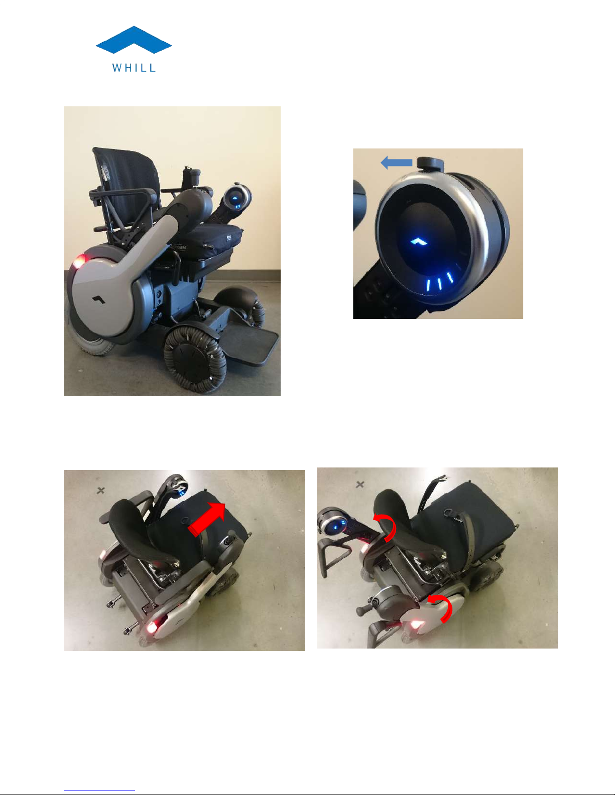
Turning the Model M On
• To turn on the Model M, pull the Mode Switch towards you once. The battery
indicator blue light(s) should turn on for a second and the logo light should
turn on and stay on.
• Around the power switch are multiple lights that indicate the amount of charge
left in the battery. To understand the battery charge indicators, see section
4.5, Checking the Battery Charge Level.
•
Pull
Page 24

USER MANUAL
MODEL M
Page 22
INFORMATION
You should not touch the directional controller when you first turn on the Model M. The
Model M has a short initialization cycle that will be interrupted if you move the
directional controller when it is starting up. Doing so will result in an error code. If this
occurs, turn off the Model M and then turn it back on, making sure not to touch the
directional controller.
Turning the Model M off
To power off the Model M, pull the Mode Switch towards you once and the Model
M will shut down.
If the power on/off does not behave as expected, refer to the Battery Charge
section of this manual or contact WHILL customer support for help.
Checking the Battery Charge Level
The battery charge is designed to last approximately 12 miles depending on
conditions, such as road, driving conditions, temperature/humidity, payload and
inclines. For more details see section 5.1, Battery Maintenance.
When the Model M is on, the blue lights indicate the amount of battery charge in the
device. These 5 lights below the mode switch display the battery charge level. The
lights will also indicate error conditions (see Section 8, Troubleshooting).
● If the device is losing charge too quickly, or if the lights indicate a wrong charge
level, please contact WHILL customer support immediately.
● If the battery charge lasts significantly less than 12 miles, contact WHILL
customer support immediately.
Lights showing full battery charge
When the Model M is on, a full battery charge is indicated by all 5 blue lights
lighting up.
USER MANUAL
MODEL M
Page 39
• Connect the round DC plug ③ to the charger port on the Model M (Figure 26).
The LED status indicator on the charger will turn orange when it is charging.
• When the charging status indicator becomes a steady green light, the
charging sequence has been completed.
Figure 26. Charger port
Depending on the condition of the battery, it may take about 10 hours to fully
charge the batteries.
Note that if the Model M is turned on during charging, you will see an error code
and will not be able to operate the Model M. In this case, unplug the charger
before turning on the power.
To unplug the chair, remove the round DC plug from the chair, and remove the
plug from the wall outlet. It is best to place the charger in a location where you
are unlikely to run over it.
Charger Troubleshooting
If the red LED on the battery charger is flashing:
• Turn off the wheelchair and disconnect the charger’s DC plug from the
wheelchair.
• Unplug the charger from wall outlet for 5 seconds. This resets the charger.
• Plug the charger back into the wall outlet and turn it on.
Page 25

USER MANUAL
MODEL M
Page 23
Lights showing intermediate charge level
Low battery indication
A low battery level (less than 37%) is indicated by one remaining blue light. If the
one blue battery light changes to red and the logo light flashes, this means the
Model M is on reserve battery charge (less than 20%) and you should charge the
device immediately.
Figure 14. Two to four lights indicate an
intermediate charge level.
Figure 13. Lights indicating full
battery charge.
Page 26

USER MANUAL
MODEL M
Page 24
Figure 15. Lights indicating low and reserve battery charge levels
If the device stops due to a dead battery and there is no immediate charging
available, refer to section 4.9, “Moving the device without power”.
INFORMATION
A red light and blue light in combination indicate an error code.
Speed Control
The operating speed is controlled by both the speed settings and directional
controller. However, the directional controller must be used for the device to move in
any direction at controlled speed.
Speed Setting
The default setting for the Mode Switch is marked with an S. In this mode, the
directional controller will move the seat forward and backward, but there is no
movement of the wheelchair. There are 3 speed settings that control the overall
speed of the device. A label next to the switch indicates the speed setting
(Figure 16). One arrow indicates low speed, a double arrow indicates medium
speed, and a triple arrow indicates high speed.
USER MANUAL
MODEL M
Page 37
Short Circuit Protection
YES
Protection Against Over Voltage
Automatically stops charging when
output voltage is 5% over Vmax
Protection Against Over Current
Automatically stops charging when
Output Current is 30% over rating
current
LED Indicator
Power /On :RED
Charging :Orange
Full Charge :Green
Protection: Red LED flash
Batteries types that can be
charged
Sealed valve-regulated lead-acid
batteries
Capacity of the batteries that can
be charged (C5)
42.5 Ampere hours (Ah)
Environmental protection rating
IPX1
Operating Temperature
0℃ - 40℃
Operating Humidity
20% - 85%
Storage Temperature
-20℃ -70℃
Use Below Altitude
2000m
Charging Connector Pin
Assignment
1: DC Output +V ( +29.4V )
2: DC Output –V ( Ground )
3: INHIBIT
Dimensions
183mm (L) x 100mm (W) x 58mm (H)
Weight
0.81 kg
Page 27

USER MANUAL
MODEL M
Page 25
Figure 16. Mode switch
Speed control through the directional controller
The speed can also be controlled by the amount of pressure you put on the
directional controller. Unlike the speed setting, the directional controller provides
continuous proportional variable speed control.
The speed adjustment using the directional controller is just like the accelerator
pedal of a car: higher pressure makes the Model M go faster, while less pressure
on the directional controller will make the Model M move more slowly.
When beginning to drive the Model M, always set the speed setting to slow (the
setting closest to you) and apply just enough pressure on the directional
controller for the device to begin moving.
Directional Controller
The directional controller is the Model M’s steering control. WHILL offers multiple
shapes of directional controllers.
The directional controller is free to move in any direction. The figures below give some
examples of the basic driving capabilities of your WHILL Model M. All of the possible
driving configurations are not shown, but can be inferred from the drawings below.
Low speed
Medium speed
High speed
Seat mode
Power
on/off
Page 28

USER MANUAL
MODEL M
Page 26
Figure 17. To drive the chair straight forward or backwards (left figure) move the directional controller
forward or back (right figure).
Move
the
directional controller away from you to drive forward. Move it towards you to drive in reverse.
Figure 18. To turn to the right (left figure) move the directional controller at a diagonal (right figure).
USER MANUAL
MODEL M
Page 35
6 Battery and Charging
The Model M includes sealed lead-acid batteries and a High Power battery charger.
These do not meet all the requirements of ISO 7176-25:2013 (the standard for safety or
batteries and chargers for powered wheelchairs) however they passed testing equivalent
to ISO 7176-25: 2013.
Before using your Model M for the first time, make sure you have fully charged the
batteries for 10 hours. The battery charger will indicate when battery charging is complete
and the wheelchair will indicate the battery charge level (see Section 4.4). It is
recommended that the battery be fully charged before you use the Model M. Occasional
use of the wheelchair prior to charging complete indication is acceptable if the need is
urgent.
With a full battery charge you should be able to drive about 15 miles under ideal
conditions. Factors that will affect the driving range include curves, terrain, driving habits,
payload, and temperature. To get the maximum range or distance per charge, WHILL
recommends the following:
• Always fully charge the batteries before a trip
• Reduce baggage weight as much as possible
• Avoid inclines and obstacles when planning your routes
• Maintain an even speed and avoid quick, frequent stops
WARNING
• Read the instructions before attempting to use the battery charger.
• Only use the original battery charger provided with the Model M. Use of any other
charger may cause damage or injury and will void the product’s warranty. Please
contact customer support if you need a replacement battery charger.
• Battery charging should only be performed indoors. Exposing the battery charger to
any moisture, water, or other elements may result in fire or electric shock.
• To reduce the risk of fire or electric shock, do not use extension cords with the
battery charger. Use of extension cords may result in damage and/or injury.
• To reduce the risk of fire or electrical shock, do not leave the Model M plugged in
and continuously charging for more than one week. Extended charging of the Model
M may result in damage and/or injury.
• Keep the wheelchair and battery charger away from sources of ignition, such as
flames and sparks, because the battery can generate explosive gasses while
charging.
Page 29

USER MANUAL
MODEL M
Page 27
Figure 19. To rotate to the right (left figure) move the directional controller directly to the right (right
figure).
Safety Check when Starting to Move
INFORMATION
• It is recommended that you have someone with you the first time you use the
Model M.
• In case of difficulty or problems, you should always have a cell phone or
communication device with you when using the Model M.
When starting to operate the Model M:
● Make sure the Model M is turned on.
● Check that both rear tail lamps are on.
● Check the battery charge level: Make sure the Model M has enough charge in it to
conduct your planned activities (see section 4.5 on Checking Battery Charge Level).
● Always start the Model M at the slowest speed setting (with the speed switch closest
to you, Figure 20).
Page 30

USER MANUAL
MODEL M
Page 28
Figure 20. Mode switch placement for slow speed setting
● Push the directional controller very slowly in the direction you wish to move the
Model M. You will feel the directional controller engaged when the device starts to
move. Keep the speed switch at the slowest speed.
● Move to a safe open space and at the slowest speed with the controller, check that
you can move in any direction you want.
● If you feel there are any new noises or vibrations, make note of these and report
them to WHILL customer support.
INFORMATION
If the logo light is flashing (and the wheelchair is not in a low battery condition), this is
an indication that the seat is not in the fully retracted position. You will have to move
the seat backwards before driving the chair.
It is recommended that you leave the device in “S” mode when not driving the chair.
Driving Conditions
The Model M is designed with four wheel drive and should provide traction and stability
in many conditions. However it is important to be aware of the limitations of the Model
M. Note that if operating the Model M in low temperature conditions the battery capacity
may be reduced and you may not be able to drive as far as in normal conditions. Other
limitations are highlighted in Figure 21 and the warnings below.
USER MANUAL
MODEL M
Page 33
• Before releasing the electromagnetic brakes, use stopping devices such as chucks
or stops to prevent the Model M from rolling away.
• Never park or transport a Model M that has a brake released.
How to release the electromagnetic brakes
To release the electromagnetic brakes, use the following steps:
• The electromagnetic brake levers are located at the front of the chair, below
the seat (Figure 23).
• Release each brake by pushing the lever down (see white arrow with unlock
symbol) (Figure 24)
Figure 23. Placement of brake release levers on Model M
Page 31

USER MANUAL
MODEL M
Page 29
Figure 21. Some key driving limitations
WARNING
• Do not operate the Model M on any streets, roads, or highways. Operating the
Model M on streets, roads, or highways may expose you to situations that may result
in severe damage and/or injury. Before crossing the street, make sure that any and
all drivers see you.
• To prevent injury and/or damage, do not use the Model M in heavy snow or icy
conditions. The Model M is not designed for use in these types of conditions.
• Do not drive the Model M through water deeper than 1”. Doing so may damage the
Model M components and make the Model M inoperable.
• Do not operate the Model M on soft surfaces such as sand or mud. Doing so may
cause you to become stuck and unable to move the Model M.
• Do not use the Model M on slopes greater than 17% as the device may become
unstable and tip over, resulting in damage and/or injury. The Model M has been
tested for stability on 17% slopes (10 degrees) and should only be used on slopes
less than 17%. For reference, a standard ramp with a railing going into a public
building has an 8.3% slope.
Page 32

USER MANUAL
MODEL M
Page 30
• Do not use the Model M to navigate objects taller than 3”. Doing so may cause the
device to become unstable and tip over, resulting in damage and/or injury. The
Model M is designed and tested for stability on obstacles less than 3” in height.
• Use extreme caution when driving on uneven surfaces or slopes. In these
conditions, the device may become unstable and tip over, resulting in damage
and/or injury. It is recommended that you have someone available to stabilize the
Model M if necessary when driving on uneven or sloped surfaces.
• Do not use the Model M as a seat during weight training. Doing so may cause the
device to become unstable and tip over, resulting in damage and/or injury. The
Model M is not intended to be used as a seat during weight training.
• Check that the tail lamps are working properly before operating the Model M at night
or in low visibility conditions. Failure to check the tail lamps could result in injury if
others cannot see the chair and collide with it.
• It is not safe to operate the Model M with the footplate in an up (vertical) position.
Make sure the footplate is down before moving.
• Make sure your hands, arms, elbows and feet are inside the Model M when moving.
• Stopping distance on slopes can be significantly greater than on level ground.
CAUTION
• Reaching or leaning can affect the stability and balance of the Model M. Always
exercise caution when shifting your weight or balance in the Model M. When in
doubt, ask for help when reaching for inaccessible objects.
In addition to the warnings and caution above, as depicted in Figure 22 to ensure a smooth
and safe ride:
• Always approach curbs, thresholds, steps, and gradients straight-on
• Always approach obstacles, curbs, steps, and gradients at low speed
USER MANUAL
MODEL M
Page 31
Figure 22. Approach all obstacles and slopes at a slow speed and straight on
Stopping and Parking
The Model M uses four wheel drive. This means that when the Model M is not
powered (either because the power is turned off or because the directional controller
is not in use), all the wheels are locked and will not move. You can power off the
device and its brakes are automatically activated– no separate parking brake is
needed.
Sitting at a Table or Desk
Because the Model M has the unique feature of a sliding seat, you can position
yourself at a table, desk or other object using the following steps:
● Position the Model M as close to the object as possible but not so close that
the arm cannot be raised
● Lift both of the side arms to the upright position
● Put the Mode Switch into the S location and use the directional controller to
extend the seat base forward
● Ensure the device is powered off
●
Page 33

USER MANUAL
MODEL M
Page 31
Figure 22. Approach all obstacles and slopes at a slow speed and straight on
Stopping and Parking
The Model M uses four wheel drive. This means that when the Model M is not
powered (either because the power is turned off or because the directional controller
is not in use), all the wheels are locked and will not move. You can power off the
device and its brakes are automatically activated– no separate parking brake is
needed.
Sitting at a Table or Desk
Because the Model M has the unique feature of a sliding seat, you can position
yourself at a table, desk or other object using the following steps:
● Position the Model M as close to the object as possible but not so close that
the arm cannot be raised
● Lift both of the side arms to the upright position
● Put the Mode Switch into the S location and use the directional controller to
extend the seat base forward
● Ensure the device is powered off
●
Page 34

USER MANUAL
MODEL M
Page 32
WARNING
• To prevent injury to your legs or knees, inspect under tables or other objects
before sliding the seat forward under them. Failure to do so may result in
injury due to hitting objects with your legs or knees.
5 Brake Release Levers
This section describes how to use the Brake Release Levers. You may want to release the
brakes and manually move the Model M when it is out of charge or otherwise inoperable.
The Brake Release Levers disengage the electromagnetic brakes from the motors. This is
called putting the Model M in “freewheel mode”. In freewheel mode there is no motor
power to the Model M AND there are no brakes. The Model M will move freely. A Model
M with one or both electromagnetic brakes released cannot be controlled using the
directional controller, even when the device is turned on.
Note that if you have the Model M in freewheel mode and try to turn it on you will see an
error code. This will occur with even one of the brakes released.
WARNING
• Only disengage the brake locks (put the Model M in freewheel mode) for emergency
and short-term use only. When the brake locks are released, the chair movement
can only be stopped by external forces (a person or object). Failure to engage the
brake locks may result in damage and/or injury if the chair moves uncontrollably.
• To prevent unintended movement, the Model M should be powered off whenever the
brake locks are being engaged or disengaged. Failure to turn the power off may
result in accidental device movement, resulting in a collision and possible damage
and/or injury.
• Do not use the Model M on a slope when the brake locks are disengaged (in
freewheel mode). When the brake locks are released, the chair movement can only
be stopped by external forces (a person or object). Failure to engage the brake
locks when on a slope will make it extremely difficult to control or stop the Model M
movement and could result in serious injury.
Best practice when releasing the brakes:
• Keep in mind that the Model M will be difficult to control in freewheel mode.
• Be strongly aware of the environment around you, especially uneven surfaces,
obstacles and people.
USER MANUAL
MODEL M
Page 29
Figure 21. Some key driving limitations
WARNING
• Do not operate the Model M on any streets, roads, or highways. Operating the
Model M on streets, roads, or highways may expose you to situations that may result
in severe damage and/or injury. Before crossing the street, make sure that any and
all drivers see you.
• To prevent injury and/or damage, do not use the Model M in heavy snow or icy
conditions. The Model M is not designed for use in these types of conditions.
• Do not drive the Model M through water deeper than 1”. Doing so may damage the
Model M components and make the Model M inoperable.
• Do not operate the Model M on soft surfaces such as sand or mud. Doing so may
cause you to become stuck and unable to move the Model M.
• Do not use the Model M on slopes greater than 17% as the device may become
unstable and tip over, resulting in damage and/or injury. The Model M has been
tested for stability on 17% slopes (10 degrees) and should only be used on slopes
less than 17%. For reference, a standard ramp with a railing going into a public
building has an 8.3% slope.
Page 35

USER MANUAL
MODEL M
Page 33
• Before releasing the electromagnetic brakes, use stopping devices such as chucks
or stops to prevent the Model M from rolling away.
• Never park or transport a Model M that has a brake released.
How to release the electromagnetic brakes
To release the electromagnetic brakes, use the following steps:
• The electromagnetic brake levers are located at the front of the chair, below
the seat (Figure 23).
• Release each brake by pushing the lever down (see white arrow with unlock
symbol) (Figure 24)
Figure 23. Placement of brake release levers on Model M
Page 36

USER MANUAL
MODEL M
Page 34
Figure 24. Close up of brake release lever
The electromagnetic brakes are now released and the Model M is free to roll. Have
someone manually push the Model M forward or backwards and verify that it rolls
freely.
How to engage the electromagnetic brake(s)
To re-engage the electromagnetic brakes and enable Model M control, use the
following steps:
● Look at the front of the Model M, below the seat, for the electromagnetic
brake levers.
● Re-engage each brake by pulling the lever up (see blue arrow with lock
symbol) (Figure 24).
Note that the lock symbol on the brake release labels has a “D” on it for “drive”.
The electromagnetic brakes are now engaged and the Model M will require battery
power in order to move.
To test if the electromagnetic brakes are engaged, do the following:
● Check to see if someone can manually push the Model M. If it rolls, the
electromagnetic brakes are not engaged.
● Turn on the Model M and check that no error code is displayed.
● Use the directional controller switch to move the Model M: it should move in
all directions.
USER MANUAL
MODEL M
Page 27
Figure 19. To rotate to the right (left figure) move the directional controller directly to the right (right
figure).
Safety Check when Starting to Move
INFORMATION
• It is recommended that you have someone with you the first time you use the
Model M.
• In case of difficulty or problems, you should always have a cell phone or
communication device with you when using the Model M.
When starting to operate the Model M:
● Make sure the Model M is turned on.
● Check that both rear tail lamps are on.
● Check the battery charge level: Make sure the Model M has enough charge in it to
conduct your planned activities (see section 4.5 on Checking Battery Charge Level).
● Always start the Model M at the slowest speed setting (with the speed switch closest
to you, Figure 20).
Page 37

USER MANUAL
MODEL M
Page 35
6 Battery and Charging
The Model M includes sealed lead-acid batteries and a High Power battery charger.
These do not meet all the requirements of ISO 7176-25:2013 (the standard for safety or
batteries and chargers for powered wheelchairs) however they passed testing equivalent
to ISO 7176-25: 2013.
Before using your Model M for the first time, make sure you have fully charged the
batteries for 10 hours. The battery charger will indicate when battery charging is complete
and the wheelchair will indicate the battery charge level (see Section 4.4). It is
recommended that the battery be fully charged before you use the Model M. Occasional
use of the wheelchair prior to charging complete indication is acceptable if the need is
urgent.
With a full battery charge you should be able to drive about 15 miles under ideal
conditions. Factors that will affect the driving range include curves, terrain, driving habits,
payload, and temperature. To get the maximum range or distance per charge, WHILL
recommends the following:
• Always fully charge the batteries before a trip
• Reduce baggage weight as much as possible
• Avoid inclines and obstacles when planning your routes
• Maintain an even speed and avoid quick, frequent stops
WARNING
• Read the instructions before attempting to use the battery charger.
• Only use the original battery charger provided with the Model M. Use of any other
charger may cause damage or injury and will void the product’s warranty. Please
contact customer support if you need a replacement battery charger.
• Battery charging should only be performed indoors. Exposing the battery charger to
any moisture, water, or other elements may result in fire or electric shock.
• To reduce the risk of fire or electric shock, do not use extension cords with the
battery charger. Use of extension cords may result in damage and/or injury.
• To reduce the risk of fire or electrical shock, do not leave the Model M plugged in
and continuously charging for more than one week. Extended charging of the Model
M may result in damage and/or injury.
• Keep the wheelchair and battery charger away from sources of ignition, such as
flames and sparks, because the battery can generate explosive gasses while
charging.
Page 38

USER MANUAL
MODEL M
Page 36
• Carry out charging with the wheelchair in a space at least twice its volume, with
sufficient ventilation that there is no hazard due to build-up of flammable gas.
• Do not use the battery charger to charge other batteries.
• Do not carry the battery charger on the wheelchair.
CAUTION
• Be sure to fully charge the batteries before any initial use of the Model M. Failure to
charge the new batteries may reduce the overall battery life.
• To prevent the batteries from draining completely, charge the Model M at least once
per month. If the batteries drain completely, do not use the Model M and have the
battery replaced as soon as possible.
INFORMATION
The batteries used are sealed valve-regulated lead-acid batteries. They do not require
maintenance.
Charger specifications for WHILL Model M
Table 5. Charger specifications for Model M
Manufacturer
High Power
Model
HP0180WB 24V 6A
Charger Type
Off board
Input Voltage Range
AC 100~240V 50/60HZ
Output Current (DC)
6.0A ± 0.3A
Output Voltage (DC)
29.4V ± 0.3V
Pre-Charge Current
0.6A ± 0.3A
Constant Current Fast Charge
21V – 28V+1V/6A
USER MANUAL
MODEL M
Page 25
Figure 16. Mode switch
Speed control through the directional controller
The speed can also be controlled by the amount of pressure you put on the
directional controller. Unlike the speed setting, the directional controller provides
continuous proportional variable speed control.
The speed adjustment using the directional controller is just like the accelerator
pedal of a car: higher pressure makes the Model M go faster, while less pressure
on the directional controller will make the Model M move more slowly.
When beginning to drive the Model M, always set the speed setting to slow (the
setting closest to you) and apply just enough pressure on the directional
controller for the device to begin moving.
Directional Controller
The directional controller is the Model M’s steering control. WHILL offers multiple
shapes of directional controllers.
The directional controller is free to move in any direction. The figures below give some
examples of the basic driving capabilities of your WHILL Model M. All of the possible
driving configurations are not shown, but can be inferred from the drawings below.
Low speed
Medium speed
High speed
Seat mode
Power
on/off
Page 39

USER MANUAL
MODEL M
Page 37
Short Circuit Protection
YES
Protection Against Over Voltage
Automatically stops charging when
output voltage is 5% over Vmax
Protection Against Over Current
Automatically stops charging when
Output Current is 30% over rating
current
LED Indicator
Power /On :RED
Charging :Orange
Full Charge :Green
Protection: Red LED flash
Batteries types that can be
charged
Sealed valve-regulated lead-acid
batteries
Capacity of the batteries that can
be charged (C5)
42.5 Ampere hours (Ah)
Environmental protection rating
IPX1
Operating Temperature
0℃ - 40℃
Operating Humidity
20% - 85%
Storage Temperature
-20℃ -70℃
Use Below Altitude
2000m
Charging Connector Pin
Assignment
1: DC Output +V ( +29.4V )
2: DC Output –V ( Ground )
3: INHIBIT
Dimensions
183mm (L) x 100mm (W) x 58mm (H)
Weight
0.81 kg
Page 40

USER MANUAL
MODEL M
Page 38
Charging the battery
Figure 25. Battery charger images and features
① AC cable receptacle
② Charging status indicator light
Green: fully charged (floating charge)
Orange: charging
Red: power on
Red LED flashing: protection
Off: disconnected
③DC plug (into chair)
④AC cable: not pictured, plugs into AC receptacle (1)
Please charge the Model M by following the steps below:
• Ensure the Model M is safely parked indoors in a well-ventilated room away
from flames and sparks and has both its brakes engaged
• Turn off the Model M
• If not already done, connect the AC cable to the battery charger’s AC
receptacle ①
• Ensure the voltage of the wall outlet is 100 V to 240 V AC
• Connect the AC cable directly into a wall outlet. The LED status indicator ②"
on the charger will turn red when the power is on.
USER MANUAL
MODEL M
Page 23
Lights showing intermediate charge level
Low battery indication
A low battery level (less than 37%) is indicated by one remaining blue light. If the
one blue battery light changes to red and the logo light flashes, this means the
Model M is on reserve battery charge (less than 20%) and you should charge the
device immediately.
Figure 14. Two to four lights indicate an
intermediate charge level.
Figure 13. Lights indicating full
battery charge.
Page 41

USER MANUAL
MODEL M
Page 39
• Connect the round DC plug ③ to the charger port on the Model M (Figure 26).
The LED status indicator on the charger will turn orange when it is charging.
• When the charging status indicator becomes a steady green light, the
charging sequence has been completed.
Figure 26. Charger port
Depending on the condition of the battery, it may take about 10 hours to fully
charge the batteries.
Note that if the Model M is turned on during charging, you will see an error code
and will not be able to operate the Model M. In this case, unplug the charger
before turning on the power.
To unplug the chair, remove the round DC plug from the chair, and remove the
plug from the wall outlet. It is best to place the charger in a location where you
are unlikely to run over it.
Charger Troubleshooting
If the red LED on the battery charger is flashing:
• Turn off the wheelchair and disconnect the charger’s DC plug from the
wheelchair.
• Unplug the charger from wall outlet for 5 seconds. This resets the charger.
• Plug the charger back into the wall outlet and turn it on.
Page 42

USER MANUAL
MODEL M
Page 40
If the battery charger does not appear to be on:
• Check the charging status light – if it is off, the charger may not be connected
to AC power.
• Check to make sure there is power at the AC receptacle.
If you need to replace the battery charger, please contact WHILL customer
support.
Battery service or replacement
To prevent problems, WHILL recommends battery replacement once a year. A weak
battery or unusually short range per charge may be indicators of battery end of life. The
batteries are designed to be serviced or replaced only by technicians qualified by
WHILL. Please do not attempt to replace the batteries on your own. If you feel that the
battery needs replacement, please contact WHILL customer support.
7 Electromagnetic Interference (EMI)
Powered wheelchairs may be susceptible to electromagnetic interference - a kind of
interfering electromagnetic energy that is emitted from sources such as radio stations, TV
stations, amateur radio (HAM) transmitters, two-way radios, and cellular phones. The
interference from these radio wave sources can cause the wheelchair brakes to release, or
the chair to move by itself or move in unintended directions. It can also permanently
damage the chair’s electronics and controls.
WARNING
• Electromagnetic Interference (EMI) from external sources can impact braking and
control of the Model M. Unintended brake release or Model M movement could
result in serious injury. To prevent this:
o DO NOT operate hand-held transceivers (transmitters/receivers), such as
citizens band (CB) radios, or turn on personal communication devices, such
as cellular phones, while the Model M is turned ON;
o Be aware of nearby transmitters, such as radio or TV stations, and try to
avoid coming close to them;
o If unintended movement or brake release occurs, turn the powered chair OFF
as soon as it is safe;
o Be aware that adding accessories or components, or modifying the powered
chair may make it more susceptible to EMI
USER MANUAL
MODEL M
Page 21
Power Switch
The power switch turns the chair on and off. Pull the switch towards you from the “S”
(seat”) position to turn the power on or off. The switch is spring-loaded so it will
return to the “S” position. When the power is on, the WHILL logo will light up (see
Figure 12).
NOTE: Depending on the configuration of a left hand or right hand controller, the
images may vary.
Figure 12. Power Switch; Illuminated LEDs
mean the chair is on
Turning the Model M On
• To turn on the Model M, pull the Mode Switch towards you once. The battery
indicator blue light(s) should turn on for a second and the logo light should
turn on and stay on.
• Around the power switch are multiple lights that indicate the amount of charge
left in the battery. To understand the battery charge indicators, see section
4.5, Checking the Battery Charge Level.
•
Pull
Page 43

USER MANUAL
MODEL M
Page 41
o Report all incidents of unintended movement or brake release to WHILL, and
note whether there is a source of EMI nearby.
EMI Sources
The sources of radiated EMI can be broadly classified into three types:
1. Hand-held compact transceivers (transmitters/receivers) with the antenna
mounted directly on the transmitting unit. Examples include: citizens band
(CB) radios, “walkie talkies”, security, fire and police transceivers, cellular
telephones and other personal communication devices
Note: Some cellular telephones and similar devices transmit signals while they are
ON, even when not being used.
2. Medium-Range mobile transceivers, such as those used in police cars, fire
trucks, ambulances and taxis. These usually have the antenna mounted on
the outside of the vehicle.
3. Long-Range transmitters and transceivers, such as commercial broadcast
transmitters (radio and TV broadcast antenna towers) and amateur (HAM)
radios.
Note: Other types of hand-held devices, such as cordless phones, laptop computers,
AM/FM radios, TV sets, CD players, cassette players and small appliances such as
electric shavers and hair dryers, so far as we know, are not likely to cause problems.
Because the emitted energy rapidly becomes more intense the closer one moves to
the transmitting antenna (source), the electromagnetic fields from handheld radio
sources (transceivers) are of special concern. It is possible to unintentionally bring
high levels of electromagnetic energy very close to your chair’s control system while
using these devices, and affect the chair’s movement and braking.
EMI Guidance Tables
The following information was generated during testing that demonstrated device compliance
with American National Standard For Wheelchairs - Volume 2, Additional Requirements For
Wheelchairs (Including Scooters) With Electrical Systems Section 21: Requirements And Test
Methods For Electromagnetic Compatibility Of Electrically Powered Wheelchairs And
Motorized Scooters.
Page 44

USER MANUAL
MODEL M
Page 42
Table 6 Guidance and Manufacturer’s Declaration – Emissions
The Model M is intended for use in the electromagnetic environment specified below. The
customer or user of the Model M should assure that it is used in such an environment.
Emissions Test
Compliance
Electromagnetic Environment – Guidance
RF Emissions
CISPR 11
Group 1
The Model M must emit electromagnetic energy in
order to perform its intended function. Nearby
electronic equipment may be affected.
RF Emissions
CISPR 11
Class B
The Model M is suitable for use in all
establishments, including domestic establishments
and those directly connected to the public low
voltage power supply network that supplies
buildings used for domestic purposes.
Harmonics
EN 61000-3-2
Class A
Flicker
EN 61000-3-3
Complies
RF emissions
CISPR 14-1
Not applicable
The Model M is not suitable for interconnection with
other equipment
RF emissions
CISPR 15
Not applicable
The Model M is not suitable for interconnection with
other equipment
Table 7 Guidance and Manufacturer’s Declaration – Immunity
The Model M is intended for use in the electromagnetic environment specified below. The
customer or user of the Model M should assure that it is used in such an environment.
Immunity Test
IEC 60601
Test Level
Compliance
Level
Electromagnetic Environment –
Guidance
Electrostatic
Discharge (ESD}
IEC 61000-4-2
±6kV Contact
±8kV Air
±6kV Contact
±8kV Air
±8kV Charged
Floors should be wood, concrete or
ceramic tile. If floors are synthetic,
the r/h should be at least 30%
Electrical fast
transient/burst
IEC 61000-4-4
±2kV for power
supply lines
±1kV for
input/output
lines
±2kV for power
supply lines
±1kV for
input/output
lines
Mains power quality should be that of
a typical commercial or hospital
environment.
Surge
IEC 61000-4-5
±1kV line(s) to
line(s)
±2kV line(s) to
earth
±1kV line(s) to
line(s)
±2kV line(s) to
earth
Mains power quality should be that of
a typical commercial or hospital
environment.
USER MANUAL
MODEL M
Page 19
Figure 7. Pivot the footplate up out of the way
if necessary. Transfer into the chair.
Figure 8. Lower the control arms to the down
position.
Figure 9. If footplate was pivoted up, return it
to the horizontal position.
Figure 10. Turn the chair on then slide the
seat backward using the directional controller.
Recommended practices when transferring into or out of the device include:
● Position the device so that the distance between it and the object from/to which
you are transferring is close enough for your safe transfer.
● Use a transfer board if necessary.
● Put the device in seat mode and slide the seat forward.
● Turn the device off while transferring.
Page 45

USER MANUAL
MODEL M
Page 43
Voltage dips, short
interruptions and
voltage variations
on power supply
input lines
IEC 61000-4-11
>95% Dip for
0.5 Cycle
60% Dip for
5 Cycles
30% Dip for
25 Cycles
>95% Dip for
5 Seconds
100% Dip for
0.5 Cycle
60% Dip for
5 Cycles
30% Dip for
25 Cycles
100% Dip for
5 Seconds
Mains power quality should be that of
a typical commercial or hospital
environment. If the user of the Model
M requires continued operation
during power mains interruptions, it is
recommended that the Model M be
powered from an uninterruptible
power supply or battery.
Power Frequency
(50/60Hz)
Magnetic Field
IEC 61000-4-8
3A/m
30 A/m
(>3A/m)
Power frequency magnetic fields
should be that of a typical
commercial or hospital environment.
Table 8 Guidance and Manufacturer’s Declaration – Immunity
The Model M is intended for use in the electromagnetic environment specified below. The
customer or user of the Model M should assure that it is used in such an environment.
Immunity Test
IEC 60601 Test
Level
Compliance
Level
Electromagnetic
Environment – Guidance
Conducted RF
IEC 61000-4-6
Radiated RF
IEC 61000-4-3
3 Vrms
150 kHz to 80
MHz
3 V/m
80 MHz to 2.5
GHz
3 Vrms (=V1)"
150 kHz to 80
MHz
20 V/m
26 MHz to 3
GHz
Portable and mobile RF
communications equipment should be
used no closer to any part of the
Model M, including cables, than the
recommended separation distance
calculated from the equation
applicable to the frequency of the
transmitter.
Recommended separation distance"
𝐷 =
3.5
𝑉1
√𝑃
150kHz to 80MHz
"
𝐷 =
3.5
𝐸1
√𝑃
80 to 800 MHz
Page 46

USER MANUAL
MODEL M
Page 44
(>3V/m=E1)
"
𝐷 =
7
𝐸1
√𝑃
800 MHz to 2.5 GHz
where P is the max power in watts and
D is the recommended separation
distance in meters.
Field strengths from fixed transmitters,
as determined by an electromagnetic
site survey, should be less than the
compliance levels (V1 and E1).
Interference may occur in the vicinity
of equipment marked with the
following symbol.
Table 9 Recommended separation distances between portable and mobile RF
communications equipment and Model M
The Model M is intended for use in the electromagnetic environment in which radiated
disturbances are controlled. The customer or user of the Model M can help prevent
electromagnetic interference by maintaining a minimum distance between portable and
mobile RF Communications Equipment and the Model M as recommended below,
according to the maximum output power of the communications equipment.
Separation distance according to frequency of transmitter (m)
Rated maximum
output
power of
transmitter (Watts)
150kHz to 80MHz
𝑑 =
3.5
𝑉1
√𝑃
80 to 800MHz
𝑑 =
3.5
𝐸1
√𝑃
800MHz to 2.5GHz
𝑑 =
7
𝐸1
√𝑃
0.01
0.12
0.12
0.23
0.1
0.38
0.38
0.73
1
1.2
1.2
2.3
10
3.8
3.8
7.3
100
12
12
23
For transmitters rated at a maximum output power not listed above, the recommended
separation distance d in meters (m) can be estimated using the equation applicable to the
USER MANUAL
MODEL M
Page 17
● Check the rear tires for signs of wear or damage. There should be no visible
deformation of tires (they should be circular). The treads should not be worn out and
there shouldn’t be any unusual soft places on the tire.
● Check the front wheels for signs of wear or damage. The rubber on the rollers
should not be worn out more than 3mm. The tire should not make any unusual noise
when it spins.
● Check the device for physical damage such as dents, scratches, or corrosion.
Awareness of the condition of your Model M will help improve the life and safety of
the device.
● Check the arms to ensure they are locked in the down position.
● If you feel there is a service or maintenance problem or if any parts are worn or need
replacement, contact WHILL customer support immediately.
Transfers into and out of the chair
WARNING
• The weight capacity of the Model M is 220 lbs. To avoid injury or Model M failure,
do not exceed this weight.
CAUTION
• Be sure to check behind you for loose clothing or other material before moving the
seat backwards. Failure to do so may result in items becoming caught in the seat
slide rails. Gather up any objects and move them out of the way to ensure no
damage is caused by seat movement.
• To avoid injuries when the seat is backing up, do not stand on the seat slide track
that is exposed when the seat is forward.
INFORMATION
● Transferring into or out of the device requires agility, awareness and extreme
caution. Practice safe loading and unloading techniques and ask for assistance if
you cannot transfer on your own.
The Model M has been designed to make transfers easy. The figures below
demonstrate the steps that you may find useful during transfer:
Page 47

USER MANUAL
MODEL M
Page 45
frequency of the transmitter, where P is the maximum output power rating of the transmitter
in watts (W) according to the transmitter manufacturer.
NOTE 1: At 80 MHz and 800 MHz, the separation distance for the higher frequency range
applies.
NOTE 2: These guidelines may not apply in all situations. Electromagnetic propagation is
affected by absorption and reflection from structures, objects, and people.
Page 48

USER MANUAL
MODEL M
Page 46
8 Troubleshooting
If only one indicator light is on and it is not the light for low battery indicator, then it is an
error code.
Error codes may be caused by:
• Trying to move the Model M with the seat in a forward slide position.
• Turning on the Model M and trying to move it while the charger is plugged in.
• Touching the directional controller when you first turn on the Model M and it is
starting up.
• One or both of the brakes are released when you turn on the Model M.
When you encounter an error code you should restart the chair. If that does not solve
the problem, please contact your distributor or WHILL customer support for assistance.
Whenever you turn on the Model M, all the battery indicator lights should illuminate,
enabling you to see if they are all operational.
9 Maintenance
WARNING
• The Model M contains no user-serviceable parts. Do not attempt to replace or repair
any parts (including the batteries). Doing so may result in damage and/or injury.
Service should only be done by a WHILL-authorized service representative.
• Do not attempt to adjust or modify the Model M. Doing so may damage the Model
M. Adjusting or modifying the Model M may also make it less stable or impact its
performance, resulting in injury if the chair tips over or is not controllable.
• Do not spray water to clean off the Model M. Moisture may damage the Model M
components and make it inoperable.
There is no service manual available to you for the WHILL Model M.
To clean the Model M, wipe it with a soft cloth or with an anti-bacterial wipe. Never spray
liquid directly on to the Model M as it could get inside the device and cause damage.
USER MANUAL
MODEL M
Page 15
Item
Specification
Horizontal location of axle
3” (75mm)
Static, impact and fatigue testing
requirements
Pass
Resistance to ignition
Pass
Test Information
The RESNA standard (Section 15) requires disclosure of the performance test results.
Some of the testing required the use of a test dummy. In all cases, the test dummy
used weighed 220 lbs. The test methods used were as specified in RESNA WC-1
Section 15. The test data are summarized below
Table 4. Model M Performance Values
Test
Value
Static stability forward – drive wheels locked
16.3○ (lock-out)
>20○ (full speed)
Static stability rearward – drive wheels locked
16.8○ (full speed)
Static stability anti-tip – drive wheels locked
17.6○ (full speed)
Maximum slope on which the chair remains upright
after testing during all applicable tests
10○
Maximum step/transition height across which
wheelchair remains stable during all applicable tests
80.0 mm (3.1 in)
Running brakes – forward-reverse command
stopping distance on level
57” (1448mm)
Continuous theoretical driving range
15.12 miles (24.33
km)
Maneuvering theoretical driving range
5.42 miles (8.72 km)
Maximum speed forward – horizontal surface
5.75 mph (2.57 m/s)
Maximum speed forward - 10○ inclined plane
(maximum safe slope)
3.87 mph (1.73 m/s)
Climatic testing – rain, hot and cold operation and
storage – pass/fail
Pass
Maximum obstacle height the chair can both climb
and descend with technique used
3.1” (80.0mm): climb
forward with run-up,
descend casters
trailing
Electrical systems – meets all requirements
Pass
Page 49

USER MANUAL
MODEL M
Page 47
It is recommended that users take the Model M to a WHILL-authorized reseller or WHILLauthorized service technician for an annual safety inspection of the device
including general wear and tear of seating and tires.
10 Transport Option
Determine if your wheelchair has the optional tie downs (securement points) installed. To
do this, look for the transportation symbol (Figure 27) on the back of the device, below the
seat (Figure 28).
Figure 27. RESNA WC-4 Section 19 transportation symbol
The symbol indicates that the wheelchair has been tested for transportability and is in
compliance with RESNA WC-4 Section 19, Wheelchairs used as seats in motor vehicles.
Page 50

USER MANUAL
MODEL M
Page 48
Figure 28. Rear view of wheelchair showing transportation sticker and tie downs
If the tie downs have not been installed on your wheelchair you will not see the symbol and
you should never sit in the wheelchair when in a motor vehicle. The following warnings
apply:
WARNING
• Do not let anyone sit in the wheelchair while in a moving vehicle.
• Transfer to the vehicle seat and use the vehicle-installed occupant restraint system.
• Make sure the brake releases are locked and secure the wheelchair so that it cannot roll
or shift.
USER MANUAL
MODEL M
Page 13
Cushions
The WHILL Model M is provided with a seat cushion. The seat base is compatible with
seat cushions 16” wide and from 16” to 20” long. Please refer to the instruction manual
provided with your cushion for warnings, maintenance, and use of the seat cushions.
WARNING
• Only use seat cushions that have been certified to pass flammability testing.
• Do not change the seat cushions in the device without having your positioning
evaluated by a seating technician. Failure to do so may result in injury due to
improper positioning.
Specifications
There is only one model of the Model M wheelchair, the specifications are listed below.
Table 2. Model M Specifications
Item
Specification
Drive System
4 Wheel Drive
Controller
WHILL Controlling System
Seat Sliding Range
5.9" (150mm)
Chair Ground Clearance
3.5" (89mm)
Maximum Speed
5.5 MPH (8.9 km/h)
Speed Settings
Fast, Medium, Slow Speed
Braking System
Electromagnetic Brake
Turning Radius
28" (711mm)
Maximum Weight Capacity
220lb (100kg)
Arm Angle (down position)
45, 48, 52, 56 degrees
Tail lamps (2)
Red lights
Batteries (2)
12V 50Ah (per battery)
Charger
6A_Charger
Charging time: 8 hours to 80% charge
Foot Support Angle
0 to 10 degrees
Foot Support Extension
0”, 1", 2", 3", 4" (0 mm, 25mm, 50mm,
75mm, 100mm)
Compatible Back Supports
VARILITE Icon back system - Low, Mid,
Tall, Deep
Page 51

USER MANUAL
MODEL M
Page 49
• Do not transport the wheelchair in the front seat of a vehicle. If it moves or shifts it can
interfere with the driver.
• Any wheelchair that has been involved in a motor vehicle accident should not be used
until inspected and tested by WHILL authorized service personnel. The structure or the
wheelchair could be compromised or components broken that could make the
wheelchair unsafe to operate or could otherwise injure you.
Using the Transport Option
This section only applies to wheelchairs that have the optional tie downs installed. If the
transport symbol is present on the wheelchair the four tie downs have been installed on
the device and it can be used as a seat in a vehicle. In the descriptions that follow, the
person in the wheelchair in a vehicle is referred to as the “occupant”.
NOTE: WHILL does not offer Wheelchair Tie-down and Occupant Restraint Systems
(WTORS). You should purchase WTORS that are compliant with RESNA WC-4 Section
18, Wheelchair Tie-down and Occupant Restraint Systems For Use in Motor Vehicles
from your wheelchair distributor.
The following warnings apply:
WARNING
• Please contact WHILL customer support with questions about using the wheelchair as a
seat in a motor vehicle.
• The wheelchair must only be transported in a vehicle that is approved for such
purposes.
• Only forward-facing use of the wheelchair in a motor vehicle is allowed.
• Only use the wheelchair in a motor vehicle as described in these instructions.
• Dynamic testing was conducted in a forward-facing wheelchair with a 172 lb crash test
dummy restrained by both pelvic and shoulder belts. Both pelvic and shoulder belts
should be used to reduce the possibility of head and chest impacts with vehicle
components.
• Make sure the brake releases are locked and secure the wheelchair so that it cannot roll
or shift
• Do not make any alterations to the wheelchair frame components or parts as these can
compromise the device’s transportability.
• The lap belt is not designed for use as an occupant restraint when riding in a motor
vehicle. To prevent damage and/or injury, you must use approved vehicle-anchored
WTORS pelvic and shoulder belts. The lap belt present on the wheelchair may be used
Page 52

USER MANUAL
MODEL M
Page 50
in addition to the vehicle-anchored occupant restraints as long as it does not interfere
with the proper positioning of the WTORS.
• Both pelvic and shoulder belt restraints that comply with RESNA WC-4 Section 18,
Wheelchair Tie-down and Occupant Restraint Systems For Use in Motor Vehicles
should be used to limit occupant movement in a crash and reduce the likelihood of
injury
• The WTORS that are used to secure the wheelchair to the vehicle and you to the
vehicle (the occupant restraints) must be installed and attached in accordance with the
manufacturer’s instructions and RESNA WC-4 Section 18, Wheelchair Tie-down and
Occupant Restraint Systems For Use in Motor Vehicles.
• Attach the WTORS only to the designated securement points on the wheelchair. Do not
connect the WTORS to any other part of the wheelchair. Doing so may result in
structural damage to the wheelchair.
• Any wheelchair-mounted accessories should be removed during transport and secured
separately in order to reduce the chance they will break loose and injure vehicle
occupants
• Sudden stops or motor vehicle accidents may damage your wheelchair. Do not used
the wheelchair until inspected and tested by WHILL authorized service personnel. The
structure or the wheelchair could be compromised or components broken that could
make the wheelchair unsafe to operate or could otherwise injure you.
Whenever feasible, people who use wheelchairs should transfer to the vehicle seat and use
the vehicle-installed, occupant restraint system.
The wheelchair must be secured into position by attaching the straps to the four tie down
bars. There are two securement points at the back of the chair (Figure 28) and one on each
side of the seat near the pressure relief handle (Figure 29).
USER MANUAL
MODEL M
Page 11
3 Product
Model M Components
Figure 1. Model M Components
Page 53

USER MANUAL
MODEL M
Page 51
Figure 29. Front tie down point
Each tie down is identified with the hook gage symbol:
Figure 30. Tie down point marking
Page 54

USER MANUAL
MODEL M
Page 52
Proper Occupant Restraint
The wheelchair provides for anchoring a pelvic-belt restraint that conforms with the
requirements of RESNA WC-4 Section 19, Wheelchairs used as seats in motor vehicles
and can be used in conjunction with a vehicle-anchored shoulder belt with standard loweranchorage connector as a crashworthy three-point-belt restraint in motor vehicles.
The angle of the pelvic-belt restraint should be between 30 and 75 degrees relative to the
horizontal and, ideally, between 45 and 75 degrees relative to the horizontal (Figure 31).
Figure 31. Preferred angles for pelvic belt restraint
Steeper side-view pelvic belt angles are especially important if the pelvic belt is intended to
be used for postural support in addition to occupant restraint in a frontal crash. Steeper
angles will reduce the tendency for a vertical gap to develop between the user and the belt
due to compliance of seat cushions and belt movement, thereby reducing the tendency for
the user to slip under the belt and for the belt to ride up on the soft abdomen during normal
use.
Steeper belt angles also reduce the tendency for upper-torso belts to pull the pelvic belt
onto the abdomen during frontal impact loading.
USER MANUAL
MODEL M
Page 9
• Battery charging should only be performed indoors. Exposing the battery charger to
any moisture, water, or other elements may result in fire or electric shock.
• To reduce the risk of fire or electric shock, do not use extension cords with the
battery charger. Use of extension cords may result in damage and/or injury.
• To reduce the risk of fire or electrical shock, do not leave the Model M plugged in
and continuously charging for more than one week. Extended charging of the Model
M may result in damage and/or injury.
• Keep the wheelchair and battery charger away from sources of ignition, such as
flames and sparks, because the battery can generate explosive gasses while
charging.
• Carry out charging with the wheelchair in a space at least twice its volume, with
sufficient ventilation that there is no hazard due to build-up of flammable gas.
• Do not use the battery charger to charge other batteries.
• Do not carry the battery charger on the wheelchair.
Electromagnetic Interference
• Electromagnetic Interference (EMI) from external sources can impact braking and
control of the Model M. Unintended brake release or Model M movement could
result in serious injury. To prevent this:
o DO NOT operate hand-held transceivers (transmitters/receivers), such as
citizens band (CB) radios, or turn ON personal communication devices, such
as cellular phones, while the powered Model M is turned ON;
o Be aware of nearby transmitters, such as radio or TV stations, and try to
avoid coming close to them;
o If unintended movement or brake release occurs, turn the Model M OFF as
soon as it is safe;
o Be aware that adding accessories or components, or modifying the powered
Model M, may make it more susceptible to EMI;
o Report all incidents of unintended movement or brake release to the powered
Model M manufacturer, and note whether there is a source of EMI nearby.
Section 6 of this user manual contains more information on EMI and how it can
affect the Model M. To properly understand EMI, please read Section 6.
Page 55

USER MANUAL
MODEL M
Page 53
For proper positioning:
• Belt restraints should not be routed outside of the wheelchair or over the wheelchair
arm supports and should not be held away from the body by wheelchair components
or parts (Figure 32).
• The belt restraint buckle of three-point belt restraints must be placed in contact with
the occupant’s body and away from wheelchair components.
• Upper-torso belt restraints should fit directly over, and be in contact with the middle
of the shoulder (Figure 33).
• The junction of the shoulder belt and pelvic belt of three-point belts should be
located near the hip opposite to the shoulder over which the diagonal belt crosses
and not near the midline of the occupant.
• Belt restraints should be adjusted as snugly as possible, consistent with user
comfort.
• Belt restraints should not be worn or twisted in a manner that reduces the area of
contact of the belt webbing with the occupant.
Figure 32. Do not place the belt restraints on the outside of the arms or wheels
Page 56

USER MANUAL
MODEL M
Page 54
Figure 33. Pelvic belt restraints should make good contact with the front and sides of the body near
the junctions of the thighs and pelvis and against the hips
Clear Zones
Clear (or clear-space) zones indicate the safe areas around the front and back of a secured
wheelchair. The recommended front clear zone (FCZ) is 26” (measured from the front of
the occupant’s head) if the occupant is restrained by both pelvic and shoulder belts and
37” inches if only a pelvic restraint is used (Figure 34 and Figure 35). It is understood that
the frontal (or forward) clearance zone (FCZ) may not be achievable for wheelchair-seated
drivers. The rear clear zone is 16” measured from the back of the occupant’s head.
Figure 34. Top view of recommended front and rear clear zones (numbers in inches)
USER MANUAL
MODEL M
Page 7
Service
• The Model M contains no user-serviceable parts. Do not attempt to replace or repair
any parts (including the batteries) on your own. Doing so may result in damage
and/or injury. Service should only be done by a WHILL-authorized service
representative.
• Do not spray water to clean off the Model M. Moisture may damage Model M
components and make it inoperable.
• Do not attempt to adjust or modify the Model M. Doing so may damage the Model
M. Adjusting or modifying the Model M may also make it less stable or impact its
performance, resulting in injury if the chair tips over or is not controllable.
Transportation
If your device is not equipped with securement points for transportation:
• Do not let anyone sit in the wheelchair while in a moving vehicle.
• Transfer to the vehicle seat and use the vehicle-installed occupant restraint system.
• Make sure the brake releases are locked and secure the wheelchair so that it cannot
roll or shift.
• Do not transport the wheelchair in the front seat of a vehicle. If it moves or shifts it
can interfere with the driver.
• Any wheelchair that has been involved in a motor vehicle accident should not be
used until inspected and tested by WHILL authorized service personnel. The
structure or the wheelchair could be compromised or components broken that could
make the wheelchair unsafe to operate or could otherwise injure you.
If your device has securement points:
• Please contact WHILL customer support with questions about using the wheelchair
as a seat in a motor vehicle.
• The wheelchair must only be transported in a vehicle that is approved for such
purposes.
• Only forward-facing use of the wheelchair in a motor vehicle is allowed.
• Only use the wheelchair in a motor vehicle as described in these instructions.
• Dynamic testing was conducted in a forward-facing wheelchair with a 172 lb crash
test dummy restrained by both pelvic and shoulder belts. Both pelvic and shoulder
belts should be used to reduce the possibility of head and chest impacts with vehicle
components.
• Do not make any alterations to the wheelchair frame components or parts as these
can compromise the device’s transportability.
• Make sure the brake releases are locked and secure the wheelchair so that it cannot
roll or shift
Page 57

USER MANUAL
MODEL M
Page 55
Figure 35. Side view of recommended front and rear clear zones (numbers in inches)
The seated head height is estimated to range from 47” for a small adult female to 61” for a
tall adult male.
The following warnings are related to clearance zones:
WARNING
• Only forward-facing use of the wheelchair in a motor vehicle is allowed.
• Sufficient forward and rearward clear space should be provided around the
wheelchair occupant (Figure 34 and Figure 35). The FCZ must be larger when a
shoulder-belt restraint is not used.
• Vehicle interior components that cannot be removed from the clear zones or that are
near the occupant’s space at a level that may come in contact with the occupant’s
head during a side-impact collision or vehicle roller, should be padded with a
material that complies with Federal Motor Vehicle Safety Standard 201.
It is strongly recommended that both pelvic and shoulder belts be used by the wheelchair
occupant.
Page 58

USER MANUAL
MODEL M
Page 56
11 Symbols
The following symbols can be found on the device or the device packaging.
Symbol
Meaning
Warning. Indicates a hazardous situation that, if not avoided, could
result in death or serious injury.
Caution. Indicates a hazardous situation that, if not avoided, may
result in property damage, minor injury, or both.
Information. Gives useful tips, recommendations and information for
efficient, trouble-free use.
Power on/off
Seat mode
Low speed
Medium speed
High speed
Catalog/model number
Serial number
Manufacturer
S
USER MANUAL
MODEL M
Page 5
2 Safety
Warnings
WARNING
Model M operation
• Do not operate the Model M without first reading this user manual. Please pay close
attention to all safety information and warnings. Contact customer support if you
need any clarification on sections that are unclear. Failure to read and understand
how to properly operate the Model M may result in damage and/or injury.
• The weight capacity of the Model M is 220 lbs. To avoid injury or Model M failure,
do not exceed this weight.
• Do not operate the Model M if the battery is depleted as you could be stranded.
• Do not use the device if there are broken components as you could be injured by
sharp edges or exposure to moving parts.
• Do not operate the Model M on any streets, roads, or highways. Operating the
Model M on streets, roads, or highways may expose you to situations that may result
in severe damage and/or injury. Before crossing the street, make sure that any and
all drivers see you.
• Do not use the Model M if it has been exposed to excessive water, is damaged in
any way, or requires service. Contact WHILL or reseller for service.
• To prevent injury and/or damage, do not use the Model M in heavy snow or icy
conditions. The Model M is not designed for use in these types of conditions.
• Do not drive the Model M through water deeper than 1”. Doing so may damage the
components and make the Model M inoperable.
• Do not operate the Model M on soft surfaces such as sand or mud. Doing so may
cause you to become stuck and unable to move the Model M.
• Do not use the Model M on slopes greater than 17% as the device may become
unstable and tip over, resulting in damage and/or injury. The Model M has been
tested for stability on 17% slopes (10 degrees) and should only be used on slopes
less than 17%. For reference, a standard ramp with a railing going into a public
building has an 8.3% slope.
• Do not use the Model M to navigate objects taller than 3”. Doing so may cause the
device to become unstable and tip over, resulting in damage and/or injury. The
Model M is designed and tested for stability on obstacles less than 3” in height.
• Use extreme caution when driving on uneven surfaces or slopes. In these conditions
the device may become unstable and tip over, resulting in damage and/or injury. It
Page 59

USER MANUAL
MODEL M
Page 57
Caution. Indicates the need for the user to consult the instructions
for use for important cautionary information such as warnings and
precautions not presented on the medical device itself.
Consult Instructions for Use
CAUTION: Federal (USA) law restricts this device to sale by or on
the order of a physician.
Dispose of this equipment according to local regulations for
electrical and electronic waste disposal
Brake release is locked
Brake release is unlocked
Indoor use only
IEC 61140 Class II electrical appliance. The product is double
insulated and does not require a safety connection to electrical
earth.
Temperature limits within which the shipping package shall be
stored and handled
Humidity limits within which the transport package shall be stored
and handled
Page 60

USER MANUAL
MODEL M
Page 58
Shipping package shall be kept in an upright position
Stacking of the shipping package is not allowed and no load should
be placed on the package
Contents of the shipping package are fragile therefore it shall be
handled with care
Shipping package shall be kept away from rain
Surface unsuitable to sit on
Surface unsuitable for stepping onto
USER MANUAL
MODEL M
Page 3
1 Introduction
Welcome
Welcome to your new WHILL device! The Model M has amazing features that we hope
will positively change the way you live your daily life.
The following items are provided to you:
• WHILL Model M powered wheelchair
• WHILL mobility device charger (High Power off-board battery charger)
• User Manual (printed or digital copy of this manual)
CAUTION
CAUTION: Federal (USA) law restricts this device to sale by or on the order of a
physician.
Manual Overview
This User Manual provides relevant guidelines for the WHILL Model M on how to safely
use important features of the device, such as the speed and directional controllers. It also
provides basic service, troubleshooting, and maintenance information.
The manual may also be used by dealers, resellers, sales people, and others who wish to
understand important features of the device in more detail.
At WHILL, we care about your safety and experience with our products. Please carefully
read and follow all the instructions in this manual.
Notations
WARNING
Indicates a hazardous situation that, if not avoided, could result in death or serious
injury.
Page 61

USER M
ANUAL
MODEL M
Page 61
Page 62

USER MANUAL
MODEL M
Page 59
12 Warranty
WHILL, Inc. (WHILL) personal mobility and wheelchair products (“Product”) are warrantied
against defects in materials and workmanship as follows, for a period from the date of your
receipt of the Product from WHILL or a WHILL-authorized third-party distributor or reseller
equal to the following: (i) with respect to the base and seat frame, five (5) years, and (ii) with
respect to the seat and back cushion, two (2) years, and (iii) with respect to the electrical and
mechanical components, one (1) years, and (iiii) with respect to the batteries and tires, six (6)
months (“Warranty Period”) in each case when used in accordance with the applicable usage
documentation. If a defect arises during the Warranty Period, WHILL will, at its option: (a)
provide replacement parts that are new and/or previously used parts that are equivalent to new
in performance and reliability to the defective parts or, with your consent, are at least
functionally equivalent to the parts they replace; or (b) exchange the affected Product with a
functionally equivalent Product that is new or formed from new and/or previously used parts
that are equivalent to in performance and reliability or, with your consent, a Product that is at
least functionally equivalent to the Product it replaces.
This warranty excludes: (i) normal depletion of consumable and/or wearable parts (such as
trim components and covers for the seat and back cushion) unless failure has occurred due to
a defect in materials or workmanship; and (ii) damage resulting from abuse, accident,
modifications, unauthorized repairs, or other causes that are not defects in materials and
workmanship.
Further this warranty does not cover any labor costs that may be incurred in connection with
installation or repair of your Product. The Product is sold primarily through third-party
distributors and/or resellers, which provide warranty repair services to WHILL customers, who
may or may not charge fees for their repair labor under separate terms and conditions. In the
event the distributor or reseller is no longer in business or has ceased to sell WHILL products,
WHILL will provide a list of authorized repair companies. Please contact WHILL to obtain a
current list of authorized repair companies.
This warranty is valid solely for customers who purchased their Product directly from WHILL or
a WHILL-authorized third-party distributor or reseller in the United States and Puerto Rico.
Some states and countries do not allow limitations on how long such warranties, conditions,
and/or implied terms may last, so the limitation described above may not apply to you. This
warranty is offered in addition to rights and remedies conveyed by consumer protection laws
and regulations that cannot be statutorily waived, and does not affect your applicable statutory
rights.
No person other than WHILL is authorized to modify this limited product warranty.
Page 63

USER MANUAL
MODEL M
Page 60
13 Customer Support
For any questions or concerns, please contact WHILL, Inc. Customer Support
Email: support@whill.us
Telephone: (844) 699-4455
Address: 285 Old County Rd # 6, San Carlos, CA 94070
USER MANUAL
MODEL M
Table of Contents!
1! Introduction .......................................................................................................................... 3!
! Welcome ........................................................................................................................ 3!
! Manual Overview ........................................................................................................... 3!
! Notations ........................................................................................................................ 3!
! Document Guidelines ..................................................................................................... 4!
! Illustrations............................................................................................................... 4!
! Product Specifications ............................................................................................. 4!
! Errors and Omissions .............................................................................................. 4!
! Intended Use .................................................................................................................. 4!
2! Safety ................................................................................................................................... 5!
! Warnings ........................................................................................................................ 5!
! Cautions ....................................................................................................................... 10!
3! Product ............................................................................................................................... 11!
! Model M Components .................................................................................................. 11!
! Arm and Seat Positions ................................................................................................ 12!
! Cushions ...................................................................................................................... 13!
! Specifications ............................................................................................................... 13!
! Dimensional Information .............................................................................................. 14!
! Test Information ........................................................................................................... 15!
4! Operation ........................................................................................................................... 16!
! Safety Check ................................................................................................................ 16!
! Transfers into and out of the chair ............................................................................... 17!
! Lap Belt ........................................................................................................................ 20!
! Power Switch ............................................................................................................... 21!
! Turning the Model M On ........................................................................................ 21!
! Turning the Model M off ......................................................................................... 22!
! Checking the Battery Charge Level ............................................................................. 22!
! Lights showing full battery charge ......................................................................... 22!
! Lights showing intermediate charge level .............................................................. 23!
! Low battery indication ............................................................................................ 23!
Page 64

 Loading...