

Page 1

®
ENGINEERING COMPANY INC.
51 Winthrop Road
Chester, Connecticut 06412-0684
Phone: (860) 526-9504
Installation Guide:
Park-Kill Module
Model WPKM1
Fax: (860) 526-4078
Internet: www.whelen.com
Sales e-mail: autosale@whelen.com
Canadian Sales e-mail: autocan@whelen.com
Customer Service e-mail: custserv@whelen.com
Safety First
This document provides all the necessary information to allow your Whelen product to be properly and safely installed.
Before beginning the installation and/or operation of your new product, the installation technician and operator must
read this manual completely. Important information is contained herein that could prevent serious injury or damage.
• Proper installation of this product requires the installer to have a good understanding of automotive electronics,
systems and procedures.
• If mounting this product requires drilling holes, the installer MUST be sure that no vehicle components or other
vital parts could be damaged by the drilling process. Check both sides of the mounting surface before drilling
begins. Also de-burr the holes and remove any metal shards or remnants. Install grommets into all wire passage
holes.
• If this manual states that this product may be mounted with suction cups, magnets, tape or Velcro®, clean the
mounting surface with a 50/50 mix of isopropyl alcohol and water and dry thoroughly.
• Do not install this product or route any wires in the deployment area of your air bag. Equipment mounted or
located in the air bag deployment area will damage or reduce the effectiveness of the air bag, or become a
projectile that could cause serious personal injury or death. Refer to your vehicle owner’s manual for the air bag
deployment area. The User/Installer assumes full responsibility to determine proper mounting location, based on
providing ultimate safety to all passengers inside the vehicle.
• For this product to operate at optimum efficiency, a good electrical connection to chassis ground must be made.
The recommended procedure requires the product ground wire to be connected directly to the NEGATIVE (-)
battery post.
• If this product uses a remote device to activate or control this product, make sure that this control is located in an
area that allows both the vehicle and the control to be operated safely in any driving condition.
• Do not attempt to activate or control this device in a hazardous driving situation.
• If this product contains strobe light(s), halogen light(s) or high-intensity LEDs, do not stare directly into these
lights at a close distance. Momentary blindness and/or eye damage could result.
• If this product contains strobe light(s), halogen light(s) or high-intensity LEDs, use only soap and water to clean
the lamp lens. Use of other chemicals could result in premature lens cracking (crazing) and discoloration. Lenses
in this condition have significantly reduced effectiveness and should be replaced immediately. Inspect and
operate this product regularly to confirm its proper operation and mounting condition. Do not use a pressure
washer to clean this product.
• It is recommended that these instructions be stored in a safe place and referred to when performing maintenance
and/or reinstallation of this product.
• FAILURE TO FOLLOW THESE SAFETY PRECAUTIONS AND INSTRUCTIONS COULD RESULT IN DAMAGE TO
THE PRODUCT OR VEHICLE AND/OR SERIOUS INJURY TO YOU AND YOUR PASSENGERS!
Automotive: Other
For warranty information regarding this product, visit www.whelen.com/warranty
©2000 Whelen Engineering Company Inc.
Form No.13554C (121503)
Page 1
Page 2

WARNING!
DISCONNECTING THE VEHICLE BRAKE LAMP
CIRCUIT USING ANY SIRENS WITH RELAY OUTPUTS
OR SWITCH CONTROLLERS COULD CAUSE
VEHICLE OR PROPERTY DAMAGE, SERIOUS INJURY
OR EVEN DEATH.
DISABLING THIS CIRCUIT IS A VIOLATION OF THE
FEDERAL MOTOR VEHICLE SAFETY STANDARD
FOR THE THIRD BRAKE LIGHT, AS WELL AS REAR
BRAKE LIGHTS.
FUNCTIONS THAT BLACK OUT THE REAR BRAKE
LIGHTS (SOMETIMES CALLED “BRAKE LIGHT CUT
OUT”) MAY INTERFERE WITH THE BRAKE SHIFT
LOCK MECHANISM, AND CAUSE THE VEHICLE TO
MOVE UNEXPECTEDLY AND DANGEROUSLY.
DISCONNECTING THE BRAKE LIGHTS IN ANY WAY
IS AT YOUR OWN
RISK AND IS NOT RECOMMENDED
BY WHELEN.
Page 2
Page 3

IMPORTANT! Installation of this equipment may effect the vehicle warranty. Whelen
Engineering recommends that the vehicle manufacturer be contacted to learn what effect,
if any, this product will have on warranty considerations.
Introduction
Proper installation of this unit will allow operator of the vehicle to activate or deactivate a desired emergency response device, such as a siren, via the transmission park neutral safety switch. There are several
ways to install this module, depending upon how and what the operator wants to activate or deactivate
when the transmission is in park. The following table indicates the state of each of the wires as determined
by the vehicle transmission.
WHITE GREY BLUE YELLOW
Forward or Reverse Gear Floating
Park or Neutral
Grounded
Open
Closed
Closed Closed
Open Closed
Installation
1. Disconnect the POSITIVE lead from the vehicle battery.
2. Connect the RED wire to +12VDC and fuse at 3 amps (customer supplied).
3. Connect the BLACK wire to chassis ground.
4. Connect the WHITE wire to the vehicle’s transmission park neutral safety switch ground signal.
5. Determine which wire is the enable wire for the device to be switched. Depending on the device, this
could be the POS, the NEG wire or the control wire.
6. Cut the device’s enable wire. Connect the YELLOW wire to the enable wire coming from the device.
NOTE: This relay has a maximum switching current of 30 amps.
7. The remaining connection is determined by how the user wishes the device to function when the
transmission is shifted into park:
• If the user wants the device to be inactive when the vehicle is in park, connect the BLUE wire to
the remaining end of the device’s enable wire.
• If the user wants the device to be active when the vehicle is in park, connect the GREY wire to the
remaining end of the device’s enable wire.
8. Reconnect the POSITIVE lead to the vehicle battery and confirm proper operation of the device.
For information on the installation of the WPKM1 with specific Whelen Engineering products, please refer
to page 3.
ENABLE
LINE
BLUE OR
GREY WIRE
(see text)
BLACK WIRE
(to chassis ground)
CUT
MODULE
Page 3
YELLOW
WIRE
(to transmission
neutral safety switch
negative ground signal)
RED WIRE
(to POS battery)
DEVICE
TO BE
SWITCHED
WHITE WIRE
Page 4
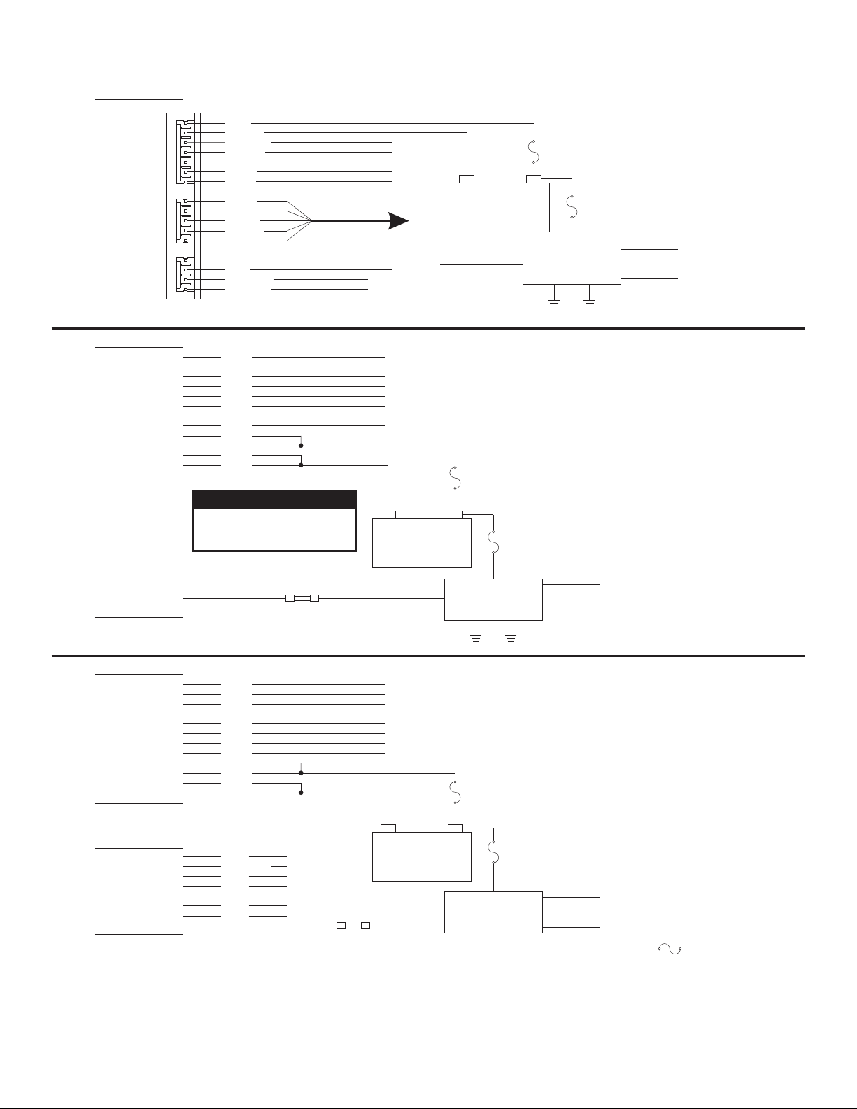
The following wiring diagrams are for use when the WPKM1 is installed with either
the MPC01 & MPC02 Multi-Purpose Controllers, or the 295HFS Series siren amplifiers
MPC01/
MPC02
POWER
COMM
AUX
CTRL
295HFSA1
295HFSA5
295HFSA6
J8
J7
J6
1
1
1
RED
BLACK
YELLOW
VIOLET
GREEN
BLUE
BLUE
BLUE
GRAY
WHITE
BLACK
SHEILD
BROWN AUXIN 1
RED AUXIN 2
ORANGE
YELLOW
WHT
GRY
YEL
BRN
ORN
BLU
BLU
VIO
RED
RED
BLK
BLK
CABLE
RS485
Park-Kill ColorModel
295HFSA1
295HFSA5
296HFSA6
PARK-KILL
(See Text
for wire color)
White/Green
Violet
Butt
Splice
12 VDC
BATTERY
Grey
Black
5 AMP FUSE
(CUSTOMER SUPPLIED)
+-
12 VDC
BATTERY
Grey
20 AMP FUSE
(CUSTOMER SUPPLIED)
+-
Red
WPKM1
PARK-KILL
MODULE
WPKM1
PARK-KILL
MODULE
Black Yellow
3 AMP FUSE
(CUSTOMER SUPPLIED)
Yellow
3 AMP FUSE
(CUSTOMER SUPPLIED)
Red
Blue
White
Blue
White
(not used)
To Neutral
Safety Switch
(see text)
(not used)
To Neutral
Safety Switch
(see text)
Siren
Amplifier
295HFS2
295HFS3
295HFS4
Control
Head
WHT
GRY
YEL
BRN
ORN
BLU
BLU
VIO
RED
RED
BLK
BLK
BLK
BLK/WHT
GRN
VIO
YEL
WHT
GRY
RED
Butt
Splice
12 VDC
BATTERY
Blue
Page 4
IMPORTANT! If the WPKM1 is used with
the 295HFS2, 295HFS3 or 295HFS4 series
siren, all siren functions including P.A. are
disabled when the WPKM1 is activated.
20 AMP FUSE
(CUSTOMER SUPPLIED)
+-
PARK-KILL
Black
3 AMP FUSE
(CUSTOMER SUPPLIED)
Red
WPKM1
MODULE
Yellow
Grey
White
(not used)
To Neutral
Safety Switch
(see text)
(customer supplied)
1 AMP fuse
To +12VDC
 Loading...