

Page 1

®
ENGINEERING COMPANY INC.
51 Winthrop Road
Chester, Connecticut 06412-0684
Phone: (860) 526-9504
Fax: (860) 526-4078
Models: TAM83, TAM83CV,
Installation Guide:
LED Traffic Advisor™
TAM8348 & TAM63
Internet: www.whelen.com
Sales e-mail: autosale@whelen.com
Canadian Sales e-mail: autocan@whelen.com
Customer Service e-mail: custserv@whelen.com
Safety First
This document provides all the necessary information to allow your Whelen product to be properly and safely installed.
Before beginning the installation and/or operation of your new product, the installation technician and operator must
read this manual completely. Important information is contained herein that could prevent serious injury or damage.
• Proper installation of this product requires the installer to have a good understanding of automotive electronics,
systems and procedures.
• If mounting this product requires drilling holes, the installer MUST be sure that no vehicle components or other
vital parts could be damaged by the drilling process. Check both sides of the mounting surface before drilling
begins. Also de-burr any holes and remove any metal shards or remnants. Install grommets into all wire
passage holes.
• If this manual states that this product may be mounted with suction cups, magnets, tape or Velcro®, clean the
mounting surface with a 50/50 mix of isopropyl alcohol and water and dry thoroughly.
• Do not install this product or route any wires in the deployment area of your air bag. Equipment mounted or
located in the air bag deployment area will damage or reduce the effectiveness of the air bag, or become a
projectile that could cause serious personal injury or death. Refer to your vehicle owner’s manual for the air bag
deployment area. The User/Installer assumes full responsibility to determine proper mounting location, based
on providing ultimate safety to all passengers inside the vehicle.
• For this product to operate at optimum efficiency, a good electrical connection to chassis ground must be
made. The recommended procedure requires the product ground wire to be connected directly to the NEGATIVE
(-) battery post.
• If this product uses a remote device to activate or control this product, make sure that this control is located in
an area that allows both the vehicle and the control to be operated safely in any driving condition.
• Do not attempt to activate or control this device in a hazardous driving situation.
• This product contains either strobe light(s), halogen light(s), high-intensity LEDs or a combination of these
lights. Do not stare directly into these lights. Momentary blindness and/or eye damage could result.
• Use only soap and water to clean the outer lens. Use of other chemicals could result in premature lens cracking
(crazing) and discoloration. Lens in this condition have significantly reduced effectiveness and should be
replaced immediately. Inspect and operate this product regularly to confirm its proper operation and mounting
condition. Do not use a pressure washer to clean this product.
• It is recommended that these instructions be stored in a safe place and referred to when performing
maintenance and/or reinstallation of this product.
• FAILURE TO FOLLOW THESE SAFETY PRECAUTIONS AND INSTRUCTIONS COULD RESULT IN DAMAGE TO
THE PRODUCT OR VEHICLE AND/OR SERIOUS INJURY TO YOU AND YOUR PASSENGERS!
Automotive: Traffic Advisor
For warranty information regarding this product, visit www.whelen.com/warranty
©2003 Whelen Engineering Company Inc.
Form No.13869E (051909)
Page 1
Page 2
Installation:
Lightb
Note: When routing wires, it is important to choose a path that will
keep the wires away from excessive heat or any vehicle equipment that
could compromise the wires integrity (trunk lids, door jams, etc.).
WARNING! When the Traffic Advisor™ is mounted to the rear of the
vehicle, the cable exit must be on the passenger side. If not, the flash
pattern sequence you choose on the control head will be incorrect. For
example a left flashing pattern will flash right.
1. Position the unit in its proposed mounting location to ensure that it fits
properly. Draw a pencil line on the mounting surface using the top and
bottom of the extrusion as a guide.
2. Two 1/4” holes are required to mount this unit. These holes may be
located anywhere along the horizontal centerline of the unit, but must
be centered between the upper and lower lines made in step 1. Tip! It’s
a good idea to locate the mounting holes as far apart as possible.
3. Using a 1/4” drill bit, drill a hole in each of the areas scribed in the
previous step.
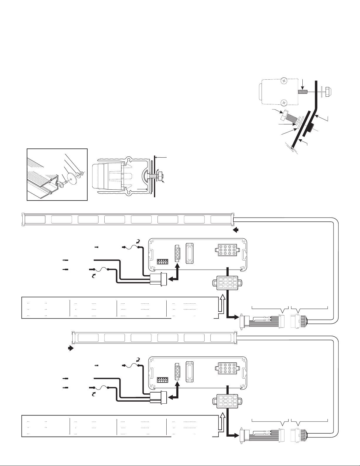
4. Remove the endcap without the cable and insert the two carriage bolts
(included) into the extrusion as shown. Position these bolts so they
may pass through the mounting holes drilled in the previous step.
#10-24 Elastic Stop Nut
#10 Flat washer
.631" Dia. x .060
Disc Gasket
#10-24 x 5/8" LG SS
Carriage Bolt
End view of extrusion / Endcap removed
EXTRUSION
DISK GASKET
FLAT
WASHER
5. With the unit in position, place a gasket, flat washer and elastic stop nut onto
each bolt and tighten firmly.
Installation Crown Vic:
1. Locate and remove the plastic covers over the tether strap holders on the
rear deck, exposing the necessary brackets.
2. Place the lightbar onto the rear deck. The lightbar carriage bolts should
already be installed as outlined in the first installation. Center the
lightbar directly behind the third
brake light.
3. Position the TAM83CV bracket
as shown and mount it to the
vehicle bracket using the
TAM83
ar
Mounting Bolt
Lightbar
Mounting
Hardware
hardware provided. Do not
tighten this hardware yet.
4. Lift the lightbar into position with
the lightbar mounting bolts
inserted through the bracket.
Secure the lightbar to the
mounting bracket. Do not tighten
this hardware yet.
5. Straighten the mounting brackets
and tighten the appropriate
5/16”
Hex Bolt
5/16”
Lockwasher
3/8”
Flat Washer
Tether Strap
Bracket
TAM83CV
Mounting
Bracket
hardware. Now tighten the hardware securing the lightbar to the mounting
bracket.
Wiring:
Extend the control wires to your switch panel and make the appropriate
connections using the wiring information below. TACTRLD1 is shown. If your
system uses another control head, refer to your control head manual for
connection and operation.
TAM83 / TAM83CV & TAM8348
1
BROWN (+)
WHITE-BROWN (-)
NOTE: Switches fuses and fuse blocks are not supplied
BACK LIGHT CONTROL: to +12VDC
source that is activated with the vehicles ignition switch
BATTERY: Negative
BATTERY: Positive
NOTE: For all information on programming and function refer to the control head instructions.
1
Lamp 1
2
Lamp 2
3
Lamp 3
TAM63
LIGHTHEAD
CONNECTIONS
NOTE: Switches fuses and fuse blocks are not supplied
BACK LIGHT CONTROL: to +12VDC
source that is activated with the vehicles ignition switch
BATTERY: Negative
BATTERY: Positive
NOTE: For all information on programming and function refer to the control head instructions.
1
Lamp 1
2
Lamp 2
3
N/C
2
RED (+)
WHITE-RED (-)
BROWN
RED
ORANGE
BROWN
RED
3
ORANGE (+)
WHITE-ORANGE (-)
POS 2 / BLACK
POS1/RED
4
Lamp 4
5
Lamp 5
6
Lamp 6
1
BROWN (+)
WHITE-BROWN (-)
POS 2 / BLACK
POS1/RED
4
Lamp 3
5
Lamp 4
6
N/C
YELLOW (+)
WHITE-YELLOW (-)
POS 3 / WHITE
10 Amp
Fuse
YELLOW
GREEN
BLUE
RED (+)
WHITE-RED (-)
POS 3 / WHITE
10 Amp
Fuse
YELLOW
GREEN
4
2
3 Amp
Fuse
7
Lamp 7
8
Lamp 8
9
Batt. / Pos
3 Amp
Fuse
7
Lamp 5
8
Lamp 6
9
Batt. / Pos
5
GREEN (+)
WHITE-GREEN (-)
3
YELLOW (+)
WHITE-YELLOW (-)
WHITE-BLUE (-)
DIP
SWITCH
CONTROL
VIOLET
GRAY
WHITE
WHITE-GREEN (-)
DIP
SWITCH
CONTROL
VIOLET
GRAY
WHITE
6
BLUE (+)
10
N/C
N/C
11
Aux. Input
12
Use SP/ST switch
fused at 3 Amps.
4
GREEN (+)
10
N/C
N/C
11
Aux. Input
12
Use SP/ST switch
fused at 3 Amps.
Page 2
78
VIOLET (+)
WHITE-VIOLET (-)
TACTLD1
REAR VIEW
20 AMP
N/C
N/C
WHT-BLU
5
VIOLET (+)
WHITE-VIOLET (-)
TACTLD1
REAR VIEW
20 AMP
N/C
N/C
WHT-BLU
GREY (+)
WHITE-GREY (-)
12 POSITION
CONNECTOR
10
7
11
8
12
9
6
GREY (+)
WHITE-GREY (-)
12 POSITION
CONNECTOR
10
7
11
8
12
9
LIGHTHEAD CONNECTIONS
1
1 = WHITE
1
2
= WHITE
1
3
= WHITE
1
4
= WHITE
1
5
= WHITE
1
6
= WHITE
1
7
= WHITE
1
8
= WHITE
1
9
= WHITE-BROWN
IO
1
4
5
2
6
3
1
4
5
2
6
3
= WHITE-RED
11
= WHITE-ORANGE
12
= WHITE-YELLOW
13
= WHITE-GREEN
14
= WHITE-BLUE
15
= WHITE-VIOLET
16
= WHITE-GREY
1
1 = WHITE
1
2
= WHITE
1
3
= WHITE
1
4
= WHITE
1
5
= WHITE
1
6
= WHITE
1
7
= WHITE
1
8
= WHITE
1
9
= WHITE-BROWN
IO
= WHITE-RED
11
= WHITE-ORANGE
12
= WHITE-YELLOW
13
= WHITE-GREEN
14
= WHITE-BLUE
15
= WHITE-VIOLET
16
= WHITE-GREY
1
1
= BROWN
1
2
= RED
1
3
= ORANGE
1
4
= YELLOW
1
5
= GREEN
1
6
= BLUE
1
7
= VIOLET
1
8
= GRAY
1
9
= WHITE-BROWN
IO
= WHITE-RED
11
= WHITE-ORANGE
12
= WHITE-YELLOW
13
= WHITE-GREEN
14
= WHITE-BLUE
15
= WHITE-VIOLET
16
= WHITE-GREY
1
1
= BROWN
1
2
= RED
1
3
= N/C
1
4
= YELLOW
1
5
= GREEN
1
6
= N/C
1
7
= VIOLET
1
8
= GRAY
1
9
= WHITE-BROWN
IO
= WHITE-RED
11
= N/C
12
= WHITE-YELLOW
13
= WHITE-GREEN
14
= N/C
15
= WHITE-VIOLET
16
= WHITE-GREY
Page 3

CAUTION! DO NOT LOOK DIRECTLY AT THESE LEDS
IMPORTANT WARNING!
WHILE THEY ARE ON. MOMENTARY BLINDNESS AND/OR
EYE DAMAGE COULD RESULT!
WARNING! All customer supplied wires that connect to the
positive terminal of the battery must be sized to supply at least
125% of the maximum operating current and FUSED at the battery
to carry the load. DO NOT USE CIRCUIT BREAKERS WITH THIS
PRODUCT!
IMPORTANT! Before returning this vehicle to active service,
visually confirm the proper operation of this product, as well as
all vehicle components/equipment.
19
5
1
2
21
20
10
11
QTYQTY
16
16
88
1
1
1
1
1
1
4
4
11
4
4
44
4
4
4
4
1
-
1
1
1
1
1
-
-
11
11
2
2
77
77
16
16
88
1
1
1
1
1
1
4
4
11
2
2
-
-
2
2
2
2
1
1
2
1
1
1
1
-
11
11
2
2
11
22
7
7
6
6
1
1
1
1
1
1
4
4
1
1
2
2
2
2
2
2
2
2
1
1
11
11
-
--
--
--
--
--
--
ITEM PART NUMBER
QTYQTYQTYQTYQTY QTY
9
9
88
1
1
1
1
11
4
4
11
2
2
2
2
2
2
2
2
1
1
11
1
1
A/RA/R
01-0684603-00
01-0684603-01
01-0684605-00
01-0684605-01
01-0684609-00
01-0684609-01
01-0684604-00
01-0684604-01
38-0463725-00
1
02-036B494612
2
46-0764808-__
3
11-443031-___
4
11-263726-000
5
14-062219-06D
6
26-0215001-03
7
8
14-104066-100
38-0223063-00
9
16-1002220-50
10
13-104120-062
11
46-0763757-00
12
46-0763757-01
13
39-0416313-04
14
21-11121602-00
15
02-0364451622
16
07-543095-000
17
38-0123089-00
18
07-243083-023
19
07-543049-000
20
38-0123071-00
21
TAM83, TIR3 NON-FLASH, switched-positive
DESCRIPTION
TAM83, TIR3 NON-FLASH, switched-ground
TAM63, TIR3 NON-FLASH, switched-positive
TAM63 TIR3 NON-FLASH, , switched-ground
TAM83CV, TIR3 with 3rd BLT. CLEAR switched-pos.
TAM83CV, TIR3 with 3rd BLT. CLEAR switched-ground
TAM8348, TIR3 NON-FLASH, switched-positive
TAM8348 TIR3 NON-FLASH, , switched-ground
DIVIDER, EXTRUSION MOUNT
ASSY TIR3 LED STEADY AMBER MUMNL,,,,
ASSY CABLE CONN ENDCAP N F,,, ,-
EXTRUSION MACH,INED
ENDCAP TIR EXTR. MT. HOLE, 3 without
SCREW #6-32 X 3/8 PPHMS ROLOK SS,"
TY WRAP, 3" BLACK
CARRIAGE BOLT #10-24 X 5/8 SS,"
GASKET, DISK
WASHER #10 FLAT .631 DIA. X .060,"
NUT, #10-24 ELASTIC STOP
CABLE ADAPTER ASS YEMBL , switched positive
CABLE ADAPTER ASS YEMBL , switched ground
HOUSING PIN 16 POS AMP,-
GROMMET
ASSY TIR LED STEADY BLUE MUMNL,3
SPACER 3RD BRAKELIGHT,
GASKET SPACER 3RD BRAKELIGHT,,
BRACKET MTG TIR T A CV REAR DECK,,3/
SPACER LIGHTHEAD,
GASKET T A SPACER TIR 48",/ , 3,
1
1
1
2
1
3
ORANGE
1
4
1
1
1
1
1
10
11
12
1
1
1
1
1
1
1
1
1
10
11
12
YELLOW
5
6
7
8
9
1
WHITE-
2
WHITE-RED
3
WHITE-ORANGE
4
WHITE-YELLOW
5
WHITE-GREEN
6
WHITE-BLUE
7
WHITE-VIOLET
8
WHITE-GREY
9
BROWN
RED
GREEN
BLUE
VIOLET
GREY
WHITE
NC
NC
NC
BROWN
WHITE
NC
NC
NC
3
4
216
1
17
18
12
CABLE ADAPTER / POSITIVE (+) SWITCHING FOR USE WITH:
SCTARM8 or SCTAREM6 CONTROL HEADS
13
CABLE ADAPTER / GROUND (-) SWITCHING FOR USE WITH:
CENCOM, TACTRL1 or TACTLD1 CONTROL HEADS
Page 3
1
1
1
2
1
3
1
4
1
5
1
6
1
7
1
8
1
9
10
11
12
13
14
15
16
1
1
1
2
1
3
1
4
1
5
1
6
1
7
1
8
1
9
WHITE-BROWN
10
WHITE-RED
11
WHITE-ORANGE
12
WHITE-YELLOW
13
WHITE-GREEN
14
WHITE-BLUE
15
WHITE-VIOLET
16
WHITE-GREY
BROWN
RED
ORANGE
YELLOW
GREEN
BLUE
VIOLET
GREY
WHITE
WHITE
WHITE
WHITE
WHITE
WHITE
WHITE
WHITE
WHITE
WHITE
WHITE
WHITE
WHITE
WHITE
WHITE
WHITE
7
8
3
Connector
(Used with both
Cable Adaptors)
10
9
11
19
10
11
6
8
14
14
15
1
1
1
2
1
3
1
4
1
5
1
6
1
7
1
8
1
9
WHITE-BROWN
10
11
WHITE-ORANGE*
12
WHITE-YELLOW
13
WHITE-GREEN
14
WHITE-BLUE*
15
WHITE-VIOLET
16
WHITE-GREY
* No Connection
with TAM63
BROWN
RED
ORANGE*
YELLOW
GREEN
BLUE*
VIOLET
GREY
WHITE-RED
 Loading...