

Page 1

®
ENGINEERING COMPANY INC.
51 Winthrop Road
Chester, Connecticut 06412-0684
Phone: (860) 526-9504
TA1252L, TA1652L & TA1652H
Traffic Advisor™ Systems
Installation Guide:
Fax: (860) 526-4078
Internet: www.whelen.com
Sales e-mail: autosale@whelen.com
Canadian Sales e-mail: autocan@whelen.com
Customer Service e-mail: custserv@whelen.com
Safety First
This document provides all the necessary information to allow your Whelen product to be properly and safely installed.
Before beginning the installation and/or operation of your new product, the installation technician and operator must
read this manual completely. Important information is contained herein that could prevent serious injury or damage.
• Proper installation of this product requires the installer to have a good understanding of automotive electronics,
systems and procedures.
• If mounting this product requires drilling holes, the installer MUST be sure that no vehicle components or other
vital parts could be damaged by the drilling process. Check both sides of the mounting surface before drilling
begins. Also de-burr any holes and remove any metal shards or remnants. Install grommets into all wire
passage holes.
• If this manual states that this product may be mounted with suction cups, magnets, tape or Velcro®, clean the
mounting surface with a 50/50 mix of isopropyl alcohol and water and dry thoroughly.
• Do not install this product or route any wires in the deployment area of your air bag. Equipment mounted or
located in the air bag deployment area will damage or reduce the effectiveness of the air bag, or become a
projectile that could cause serious personal injury or death. Refer to your vehicle owner’s manual for the air bag
deployment area. The User/Installer assumes full responsibility to determine proper mounting location, based
on providing ultimate safety to all passengers inside the vehicle.
• For this product to operate at optimum efficiency, a good electrical connection to chassis ground must be
made. The recommended procedure requires the product ground wire to be connected directly to the NEGATIVE
(-) battery post.
• If this product uses a remote device to activate or control this product, make sure that this control is located in
an area that allows both the vehicle and the control to be operated safely in any driving condition.
• Do not attempt to activate or control this device in a hazardous driving situation.
• This product contains either strobe light(s), halogen light(s), high-intensity LEDs or a combination of these
lights. Do not stare directly into these lights. Momentary blindness and/or eye damage could result.
• Use only soap and water to clean the outer lens. Use of other chemicals could result in premature lens cracking
(crazing) and discoloration. Lens in this condition have significantly reduced effectiveness and should be
replaced immediately. Inspect and operate this product regularly to confirm its proper operation and mounting
condition. Do not use a pressure washer to clean this product.
• It is recommended that these instructions be stored in a safe place and referred to when performing
maintenance and/or reinstallation of this product.
• FAILURE TO FOLLOW THESE SAFETY PRECAUTIONS AND INSTRUCTIONS COULD RESULT IN DAMAGE TO
THE PRODUCT OR VEHICLE AND/OR SERIOUS INJURY TO YOU AND YOUR PASSENGERS!
Automotive: Traffic Advisor
For warranty information regarding this product, visit www.whelen.com/warranty
©2002 Whelen Engineering Company Inc.
Form No.13724C (040910)
Page 1
Page 2
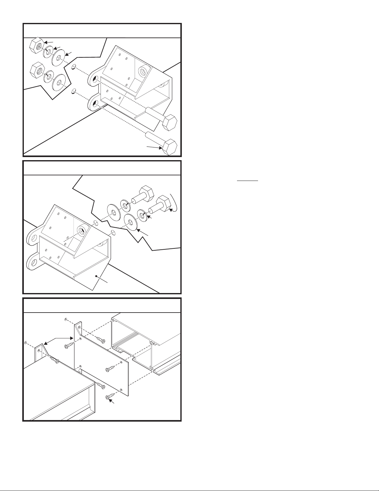
Mounting
Surface
Fig. 1
Mounting
Surface
Standard Mounting Kit
3/8" - 16 X 1" Hex Head Bolt
3/8" Split Lockwasher
3/8" Flatwasher
Mounting
Mounting
Surface
Surface
Installation:
Install the T/A arrow light array as shown in Figures 1-3
depending on which mounting style you will use.
IMPORTANT: When you are routing any wires, the
existing, factory wire harness should be followed
whenever possible. The existing harness has been
carefully positioned so that the wires could not be
damaged by vehicle operation for example; if your
vehicle is equipped with a dump body, the harness is
positioned so that the dumping action will not crush
or pinch the wires. The factory harness may,
depending on vehicle design, include a service loop
that will keep the wires from being damaged or
broken by the movement of the dump body.
Fig. 2
Fig. 3
3/8"-16X1"HexHeadBolt
Arrow End Mounting Kit
Mounting
Mounting
Surface
Surface
Base
Casting
Endcap Mounting Bracket
Mounting
Bracket
#10 X 3/4"
PPHSMS
3/8"-16X2"
Hex Head Bolt
3/8" Split
Lockwasher
3/8" Flatwasher
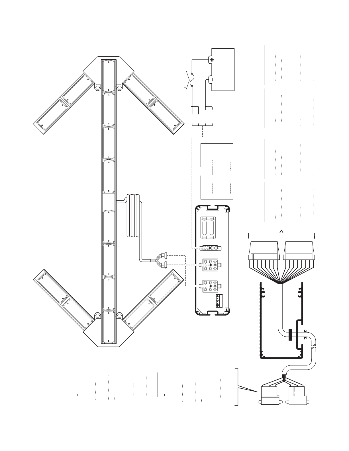
Wiring:
WARNING! All customer supplied wires that connect
to the positive terminal of the battery must be sized
to supply at least 125% of the maximum operating
current and FUSED
DO NOT USE CIRCUIT BREAKERS WITH THIS
PRODUCT!
Power Connector / P1
1. Plug the power connector into the back of the control head
as shown in the wiring diagram.
Splice the 2 RED wires together, then extend this single RED
wire to the battery. Install a 30 amp fuse block (customer
supplied) to the end of the wire (remove the fuse before
connecting any wires to the battery) and connect it to the
POSITIVE (+) terminal on the battery.
IMPORTANT: There must not be more than 2 feet of
wire between the fuse block and the battery. The wire
between the fuse and battery is “unprotected”, don’t
allow this wire to come in contact with other wires.
2. Splice the 2 BLACK wires together, then extend this single
BLACK wire to the battery and connect it to the battery
ground. If your vehicle has a cable extending from the
negative terminal of the battery to the chassis, it is best to
attach the black wire at the chassis connection.
Control Connectors / P2 & P3
1. Route the control cables from the TA to the control head.
2. Plug the connector(s) into the control head as shown.
3. Refer to the control head manual for operation.
The installation of your system will be complete after the fuse
block wire is connected to the POSITIVE (+) terminal of the
battery. After this connection has been made, inspect the fuses
at the control head and at the battery. If either of these fuses are
blown, carefully inspect all of the circuit wires and make sure
they are wired correctly. Replace blown fuses with one of an
identical amp rating. If these fuses blow after installation or
activation, contact Whelen Engineering Technical Support.
at the battery to carry that load.
Page 2
Page 3
N/C
N/C
BLUE
N/C
N/C
GREEN
LAMP 8A
LAMP 7A
TA1252L and TA652H system wiring is the same.
TA1252L / TA1652L / TA1652H
NOTE: The TA1652L Arrow is shown for reference only.
Traffic Advisor™ System / Wiring Diagram
LAMP 7CLAMP 6LAMP 5BLAMP 5A
LAMP 4BLAMP 4ALAMP 3
WHITE W/BLUE
NEG POS
BATTERY
LAMP 7B
FUSE / CUSTOMER SUPPLIED:
30 AMP / For 12 volt system
15 AMP / For 24 volt system
LAMP 8B
RED
RED
BLACK
+12VDC
FUNCTIONCOLORPOS
BLACK
+12VDC
GROUND
GROUNDBLACK
P1
RED
RED
BLACK
F1
15 AMP
123
F2
15 AMP
4
POS. COLOR
9
GRAY
16-POSITION HOUSING / P1 / RIGHT
POS. COLOR1243
N/C
POS. COLOR
9
BROWN
16-POSITION HOUSING / P2 / LEFT
POS. COLOR1243
101211
N/C
N/C
WHITE W/GRAY
N/C
ORANGE
WHITE W/ORANGE
101211
N/C
N/C
WHITE W/BROWN
13
VIOLET
5
N/C
13
RED
5
P2 / LEFT
WHITE W/GREEN
151614
N/C
N/C
WHITE W/VIOLET
786
N/C
YELLOW
WHITE W/YELLOW
151614
N/C
N/C
WHITE W/RED
786
P1 / RIGHT
P1P2P3
See Control Head Manual for
functions and programming
LAMP 1A
LAMP 2A
J1 / LEFT
-9 POSITION
HOUSING
BROWN
POS. COLOR
1
LAMP 2C
RED
WHITE W/RED
WHITE W/BROWN
243
ORANGE
WHITE W/ORANGE
5
LAMP 2B
YELLOW
WHITE W/YELLOW
786
N/C
9
LAMP 1B
-
HOUSING
J2 / RIGHT
9 POSITION
Page 3
GREEN
POS. COLOR
1
BLUE
WHITE W/BLUE
WHITE W/GREEN
243
DIP
SWITCH
CONTROL
VIOLET
WHITE W/VIOLET
5
45
32
CONTROL HEAD
REAR VIEW
1
SECTION VIEW
N/C
GRAY
WHITE W/GRAY
786
9
J1
LEFT
J2
RIGHT
Page 4
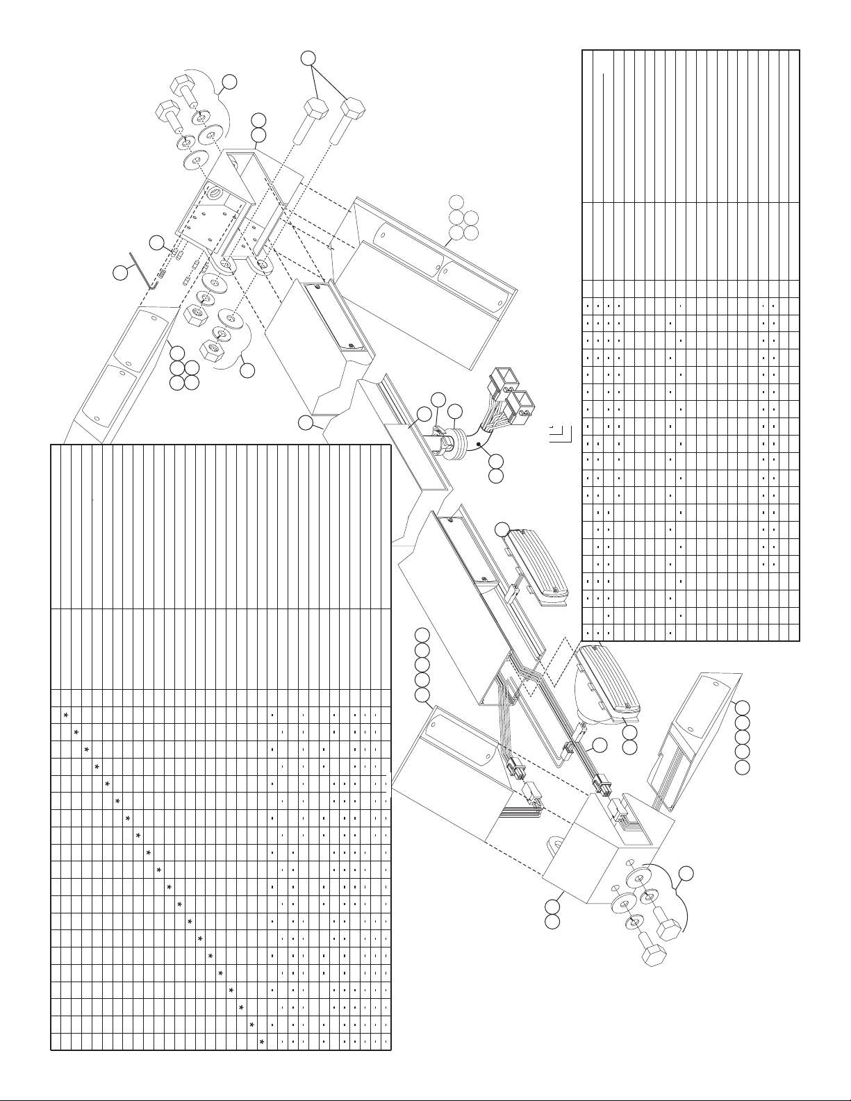
2
DESCRIPTION
TAARROW 12 LIGHT AMB 12VDC 51' CABLE END MT
TAARROW 12 LIGHT AMB 12VDC 26' CABLE END MT
TAARROW 12 LIGHT AMB 12VDC 51' CABLE STD MT
TAARROW 12 LIGHT AMB 12VDC 26' CABLE STD MT
TAARROW 16 LIGHT AMB 12VDC 26' CABLE STD MT
PART NUMBER
01-06836122A1
01-06836122A0
01-06836120A1
01-06836120A0
01-06836121A0
ITEM
QTY
QTYQTYQTYQTYQTYQTYQTYQTYQTYQTYQTYQTYQTYQTYQTYQTYQTYQTYQTY
23
29
10
9
8
TAARROW 16 LIGHT AMB 24VDC 26' CABLE STD MT
TAARROW 16 LIGHT AMB 24VDC 26' CABLE END MT
TAARROW 16 LIGHT AMB 24VDC 51' CABLE STD MT
TA ARROW 16 LIGHT AMB 24VDC 51' CABLE END MT
TAARROW 16 LIGHT AMB 12VDC 51' CABLE END MT
TAARROW 16 LIGHT AMB 12VDC 51' CABLE STD MT
TAARROW 16 LIGHT AMB 12VDC 26' CABLE END MT
01-0683612110
01-0683612310
01-06836123A1
01-06836121A1
01-06836123A0
01-0683612111
01-0683612311
1
30
2
11
TA ARROW 16 LIGHT AMB LED 51' CABLE STD MT
TA ARROW 16 LIGHT AMB LED 26' CABLE END MT
TA ARROW 16 LIGHT AMB LED 26' CABLE STD MT
TAARROW 12 LIGHT AMB LED 26' CABLE STD MT
TAARROW 12 LIGHT AMB LED 26' CABLE END MT
TA ARROW 12 LIGHT AMB LED 51' CABLE STD MT
TA ARROW 12 LIGHT AMB LED 51' CABLE END MT
01-06836121F0
01-06836120F0
01-06836122F0
01-06836120F1
01-06836122F1
01-06836123F0
01-06836121F1
21 22
20
WATER RESISTANT T/A HARNESS
HALOGEN SNAP-IN 2 WIRE 2 POS 28V-35W AMB.
HALOGEN SNAP-IN 2 WIRE 2 POS 12V-20W AMB.
MOUNTING STANDARD KIT
MOUNTING ARROW END MOUNT KIT
TAARROW 16 LIGHT AMB LED 51' CABLE END MT
01-06836123F1
01-0416047-00
01-0416050-00
01-06835777A2
01-06835777A4
46-0786468-00
2
3
5
4
1
1
1
22
88
1
2
8
1
2
1
2
88
1
2
8
1
2
1
2
88
1
2
8
1
88
1
22
1
2
8
1
1
2 2
1
1
1
2 2 2
1
1
1
2 2 2
INPUT CABLE - 51'
INPUT CABLE - 26'
WING UP. RIGHT/LOW. LEFT 8.687" BLK 12V AMB LED
WING UP. RIGHT/LOW. LEFT 8.687" BLK 12V AMB HALO
WING UP. RIGHT/LOW. LEFT 14.062" BLK 12V AMB HALO
WING UP. RIGHT/LOW. LEFT 14.062" BLK 24V AMB HALO
02-0363391-F1
02-0363391-A1
46-0764562-51
46-0764562-26
6
1 1
1
1
1 1
1
1
1
1
8
7
22
1
2
1
2
11
1
1
1
1
11
9
2 2 2 2
02-0363391-12
02-0363391-A2
11
10
2
2 2 2
2 222
25
17
WING UP. LEFT/LOW. RIGHT 8.687" BLK 12V AMB HALO
15 31
02-0363392-A1
13
12 14
12
22
22
(CONTINUED BELOW)
Page 4
26'
51'
CABLE LENGTH0=1=
14
13
12
15 31
12V AMBER HALOGEN
VOLTAGE/COLOR/STYLE
A=1=F=
STANDARD MOUNT 12 LIGHT
MOUNTING & ARROW SIZE0=1=2=3=
24
7
6
PART NUMBER EXAMPLE:
01-0683612-___
16
WING UP. LEFT/LOW. RT. 8.687" BLK 12V AMB LED
WING UP. LEFT/LOW. RT. 14.062" BLK 12V AMB HALO
12V AMBER L.E.D.
24V AMBER HALOGEN
02-0363392-F1
02-0363392-A2
13
14
STANDARD MOUNT 16 LIGHT
END MOUNT 12 LIGHT
END MOUNT 16 LIGHT
VOLTAGE-COLOR-STYLE
CABLE LENGTH
MOUNTING-ARROW SIZE
222 2
2 2 22
500 LED STEADY MAX AMBER 2 POS
HOUSING - BLACK
LABEL - MODEL - PART & SERIAL # / not shown
LABEL MADE IN USA FLAG- / not shown
FILLER PANEL
WING UP. LFT/LOWER RT 14.062" BLK 24V AMB HALO
11-463399-001
09-1322911-00
10-0522842-**
10-0320776-00
02-0363392-12
02-0383558AA4
20
19
18
17
16
15
111
1
111
1
1
1
1
1
1
1
11
11
1
1
1
1
1
1
11
1
11
1
11
1
1
1
1
222
11
1
1
11
1
1
1
1
1
1
2
11
1
1
11
1
1
88
1
1
1
1
8
1
1
11
11
11
88
1
1
1
1
8
1
1
11
1
1
11
88
SCREW 1/4-20 X 1/2" SOCKT SET CUP POINT SS-
CASTING BASE BLACK STANDARD-
CABLE CLAMP
CASTING BASE BLACK END TAPPED-
GROMMET
11-382096-002
14-130526-080
26-0121053-04
21-11233202-0
11-382096-003
21
22
23
25
24
1
1
2
20
1
1
2
20
1
2
20
2
11
111
2
20 20
1
2
20
111
2
2020
11
2
111
1
2
20
2
2020
11
2
1
111
2
20
2
20
11
2
20
1
2
20
2
20
111
11
2
20
111
1
2
20
2
20
11
2
20
WING UP. LEFT/LOW. R. 14.062" BLK 12V AMB LED
WING UP. RT.-LOW. LEFT 14.062" BLK 12V AMB LED
SEAL WIRE 9 POS UNIVERSAL MATE-N-LOK-
1/8" ALLEN WRENCH
HOUSING PLUG, 3 X 3 POS UMNL-
HOUSING 9 POS PIN AMP-
02-0363392-F2
02-0363391-F2
66T0516435102
39-1V17270-01
39-0409313-04
39-0917517-09
31
30
29
28
27
26
1
2
2
2
1
2
2
2222
1
2
2
11
22
22
1
2
2
222222
11
22
22
1
2
2
11
22
22
1
2
2
222222
11
22
22
1
2
2
11
2
2
22
22
1
222
2
2
2
2
2
2
11
22
22
2
2
SEAL - INTERFACE 9 POS UMNL
PLUG - KEYING UNIVERSAL MATE-N-LOK
39-1V17144-02
39-1V17270-00
32
33
2
2
2
2
2
2
22
22
2
2
22
22
2
2
22
22
2
2
22
22
2
2
22
22
2
2
22
22
30
11
5
3 4
10
89
1
2221
 Loading...