

Page 1

®
ENGINEERING COMPANY INC.
51 Winthrop Road
Chester, Connecticut 06412-0684
LFL Liberty™ LC 2010 Lightbar
Installation Guide:
Phone: (860) 526-9504
Fax: (860) 526-4078
Internet: www.whelen.com
Sales e-mail: autosale@whelen.com
Canadian Sales e-mail: canadiansales@whelen.com
Customer Service e-mail: custserv@whelen.com
Safety First
This document provides all the necessary information to allow your Whelen product to be properly and safely installed.
Before beginning the installation and/or operation of your new product, the installation technician and operator must
read this manual completely. Important information is contained herein that could prevent serious injury or damage.
• Proper installation of this product requires the installer to have a good understanding of automotive electronics,
systems and procedures.
• Failure to use specified installation parts and/or hardware will void the product warranty!
• If mounting this product requires drilling holes, the installer MUST be sure that no vehicle components or other
vital parts could be damaged by the drilling process. Check both sides of the mounting surface before drilling
begins. Also de-burr any holes and remove any metal shards or remnants. Install grommets into all wire
passage holes.
• If this manual states that this product may be mounted with suction cups, magnets, tape or Velcro®, clean the
mounting surface with a 50/50 mix of isopropyl alcohol and water and dry thoroughly.
• Do not install this product or route any wires in the deployment area of your air bag. Equipment mounted or
located in the air bag deployment area will damage or reduce the effectiveness of the air bag, or become a
projectile that could cause serious personal injury or death. Refer to your vehicle owner’s manual for the air bag
deployment area. The User/Installer assumes full responsibility to determine proper mounting location, based
on providing ultimate safety to all passengers inside the vehicle.
• For this product to operate at optimum efficiency, a good electrical connection to chassis ground must be
made. The recommended procedure requires the product ground wire to be connected directly to the NEGATIVE
(-) battery post.
• If this product uses a remote device to activate or control this product, make sure that this control is located in
an area that allows both the vehicle and the control to be operated safely in any driving condition.
• Do not attempt to activate or control this device in a hazardous driving situation.
• This product contains either strobe light(s), halogen light(s), high-intensity LEDs or a combination of these
lights. Do not stare directly into these lights. Momentary blindness and/or eye damage could result.
• Use only soap and water to clean the outer lens. Use of other chemicals could result in premature lens cracking
(crazing) and discoloration. Lenses in this condition have significantly reduced effectiveness and should be
replaced immediately. Inspect and operate this product regularly to confirm its proper operation and mounting
condition. Do not use a pressure washer to clean this product.
• It is recommended that these instructions be stored in a safe place and referred to when performing
maintenance and/or reinstallation of this product.
• FAILURE TO FOLLOW THESE SAFETY PRECAUTIONS AND INSTRUCTIONS COULD RESULT IN DAMAGE TO
THE PRODUCT OR VEHICLE AND/OR SERIOUS INJURY TO YOU AND YOUR PASSENGERS!
Automotive: Lightbars
For warranty information regarding this product, visit www.whelen.com/warranty
©2010 Whelen Engineering Company Inc.
Form No.14349B (052212)
Page 1
Page 2
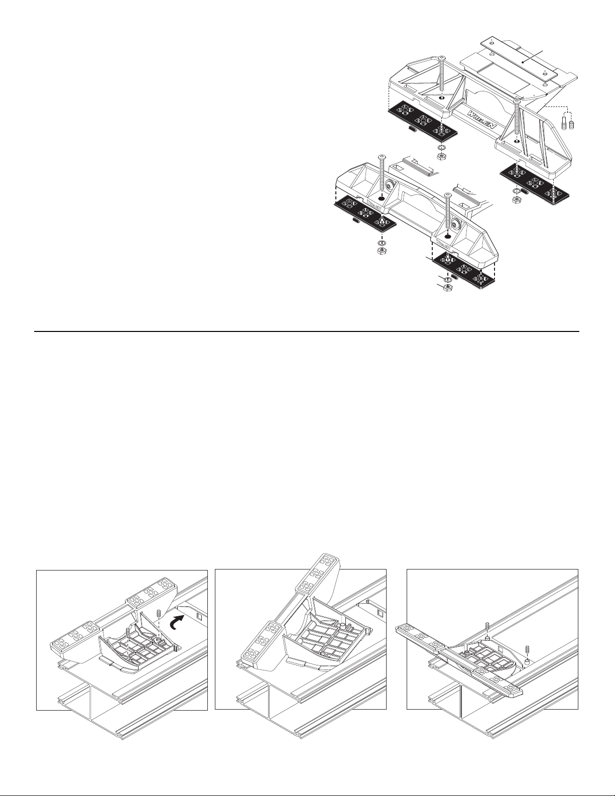
Insert foot into extrusion with locking plate
attached.
Twist mounting foot into
position
ANCHOR
PLATE
Loosely secure foot and locking plate.
Mounting
Pad
Adjustable
Mounting Foot
Washer
Nut
Standard
Mounting Foot
Bolt
Bolt
Locking
Plate
Permanent Mounting:
WARNING: Permanent mounting of this product will require drilling. It is absolutely necessary to
make sure that no other vehicle components could be damaged by this process. Check both sides
of the mounting surface before starting. If damage is likely, select a different mounting location.
1. Locate the mounting foot and locking plate included with your lightbar. If not already present,
install the locking plate onto the mounting foot using the supplied set screws. This plate should be
centered from side to side on the mounting foot.
2. Flip lightbar upside-down to expose bottom of extrusion and place mounting foot onto extrusion.
3. Rotate the mounting foot 90° in a counter-clockwise direction. Make sure that the edges of the foot
swing into position under the extrusion mounting lip.
4. Repeat procedure for remaining foot and return lightbar to its right side-up position.
5. Position the lightbar onto the vehicle roof in the desired mounting location. One often
selected location is directly above the B-pillars. This area is the strongest part of
the roof. Refer to your lightbar manual for your lightbars cable exit location, so that
the lightbar is facing the proper direction.
6. Adjust the two mounting feet outwards as close to the edge of the roof as
possible. Make sure that both mounting feet are in full contact with the roof (See
below). There should be no less than 1/2” clearance between the roof and the
lightbar at their closest point. When the mounting feet are in the proper position, lightly
tighten the allen head set screws.
7. Turn the lightbar upside down and firmly tighten all of the set screws from step 6
(2 or 4 per side).
8. On both the standard foot or the adjustable foot, use the hole in the pad as a guide to drill the two holes
into the mounting foot.
9. Place the lightbar in its final mounting position on the vehicle and mark the mounting hole locations off onto
the mounting surface. Remove lightbar and drill the mounting holes.
10. Place the lightbar back onto the vehicle lined up with the mounting holes and secure the mounting feet to the vehicle using the supplied hardware.
Strap Mounting:
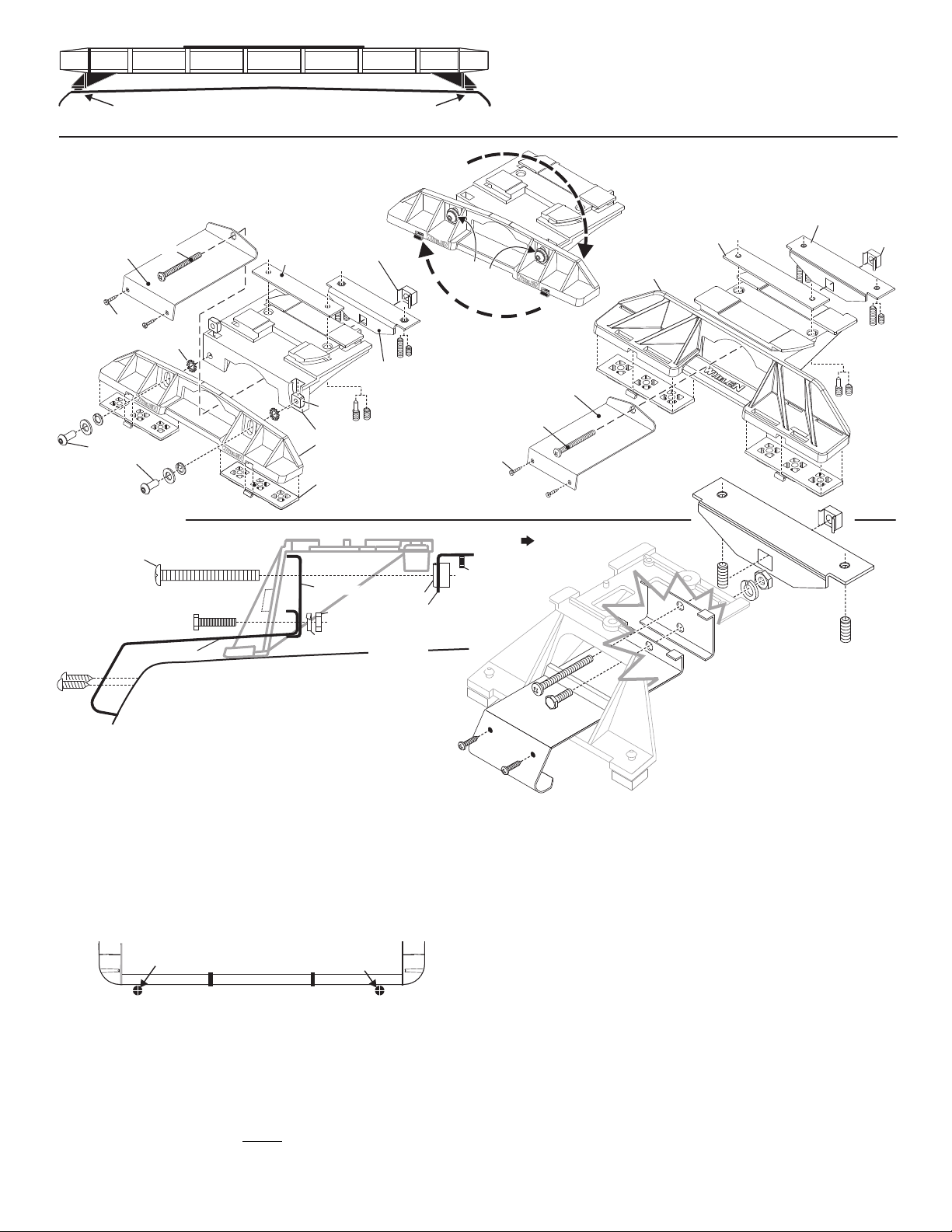
1. Locate the mounting foot, locking plate, anchor plate and tinnerman nut
supplied with the lightbar. If not already present, install the locking plate onto
the mounting foot. Center this plate from side to side on the foot.
2. Flip the lightbar upside-down to expose the bottom of the extrusion. First
slide the anchor plate into the extrusion, then place the mounting foot onto
the extrusion.
3. Rotate the mounting foot counter-clockwise 90°. The edges of the mounting
foot must swing into position under the extrusion mounting lip.
4. Repeat this procedure for the remaining mounting foot and return the
lightbar to its right side-up position.
5. Position the lightbar onto the vehicle roof in the desired mounting location.
One often selected location is directly above the B-pillars. This area is the
strongest part of the roof. Refer to your lightbar manual for cable exit
location, to be sure that the lightbar is facing the proper direction.
6. Adjust the two mounting feet outwards so that they are as close to the edge
of the roof as possible. Both mounting feet must be in full contact with the
roof. Be sure that there is no less than 1/2” clearance between the roof and
the lightbar at their closest point. When both mounting feet are in their
proper position, lightly tighten the allen head set screws.
7. Return the lightbar to an upside down position. Slide each anchor plate
outwards until it is fully engaged with its corresponding mounting foot. With
the mounting foot and anchor plate in their proper positions firmly tighten all
of the set screws (2 or 4 per side). Flip the lightbar right side-up and return it
to its mounting position.
8. Open both drivers side doors. In the area directly below the mounting foot,
carefully pull the drivers side weather-strip away from the vehicle. Remove
enough so that the area where the mounting strap will be secured to the
vehicle is exposed. Repeat for passenger side.
9. Insert the mounting strap through the mounting foot. Be sure that the strap
fits flush against the area where it will be secured onto the vehicle. Insert the
tension bolt through the mounting strap and into the anchor plate and secure
it with the tinnerman nut. Tighten slightly with a long shafted, Phillips
screwdriver. Repeat procedure for passenger side.
10. If your mounting strap has mounting holes in the end, use these holes as a
template to drill holes through the strap and into the vehicle and secure it
with sheet metal screws. Repeat passenger side.
11.Firmly tighten the tension bolts to secure the lightbar to the vehicle.
Page 2
Page 3
Drill cable access hole in appropriate area
REAR OF LIGHTBAR
For cables exiting
the Driver-side
For cables exiting
the Passenger-side
NOTE: Unless otherwise specified, the lightbar mounting feet must be
sitting as close to the edge of the roof as possible, in full contact with
the roof and not be hanging off the edge.
IMPORTANT: For strap mounted bars, be sure you have the right size
lightbar for your vehicle. The bar should be approximately the same
width as the vehicle roof. If too large or small it will not mount properly
to the vehicle and may come loose.
Locking
Plate
Mounting
Foot
Nut
Mounting
Pad
Adjustment
screws
Lock
Washer
Anchor
Plate
Tinnerman
Nut
Tinnerman
Nut
Anchor
Plate
Locking
Plate
Mounting
Strap
Mounting
Screw
Adjustable Mounting Foot / Model MKAJ
Standard Mounting Foot / Model MKEZ
Tighten screws
with torque wrench
set at 35 to 40 in/lbs
Mounting
Strap
Mounting
Screw
Tension
Bolt
Tension
Bolt
Model
MKAJ
Mounting
Foot
5" Mounting Foot
BOLT
METAL SCREW
NOTE: The mounting straps are made to fit the contours of individual
vehicles. The strap shown here is for example only. The strap
for your vehicle may look different.
NOTE:
NOTE:
STRAP
SHEET
METAL
SCREWS
MOUNTING FOOT
TINNERMAN
NUT
FOOT
ANCHOR
PLATE
SET
SCREW
Plate slides into
lightbar extrusion
NUT
SPLIT LOCK
WASHER
EXTENSION
VEHICLE ROOF
1/2" Minimum Clearance at Closest Point
Mounting should be feet as close to edge of roof as possible
On this model you may loosen the screws on the rear of the foot and adjust the
angle of the lightbar. This is used if the angle of the roof is not level with the road.
IMPORTANT: To adjust the leveling screws you must use a torque wrench
set at 35 to 40 ft. lbs
IMPORTANT! The lightbar should be a minimum of 16" from any
radio antennas!
Routing your Lightbar Cable(s)
1. To protect the headliner from damage, allow a 5” to 7” distance between roof
and headliner by lowering the headliner before drilling.
WARNING!There may be a roof support member that spans the distance
between the driver’s and passenger’s side. DO NOT DRILL THROUGH
THIS MEMBER! Adjust the location until the hole can be drilled without
contacting this support member.
2. Using a 1” hole saw, drill the cable access hole. Use a round file to smooth
and de-burr the edges than insert a 1” grommet.
3. Insert cable(s) through cable access hole into the vehicle. Use RTV silicone
to weatherproof access hole after the cable(s) are pulled completely into
vehicle. Route the cable(s) following manufacturers recommendations.
WARNING: Many vehicles are now equipped with side curtain and
B-pillar air bags. Alternate routing may be required.
WARNING! All Customer supplied wires that connect to the positive
terminal of the battery must be sized to supply at least 125% of the
maximum operating current and FUSED
DO NOT USE CIRCUIT BREAKERS WITH THIS PRODUCT!
at the battery to carry that load.
Control Cable:
Refer to the chart on the next page for wire function and fusing. Apply +12 VDC
to a control wire to activate it’s function. Extend the control wires to a customer
supplied switch box and connect following the switch box instructions.
Power Cable:
1. Open the wire shield lid and route the power cable into the wire shield,
towards the firewall. Do not to pinch or crush any wires.
2. Follow the factory wiring harness through the firewall. If you need to drill a
hole in the firewall, be sure there are no components that could be
damaged. After you drill the hole, insert a grommet to protect the cable.
3. Route the cable along the factory wiring harness to the battery.
4. Install a 30 amp fuse block (customer supplied) on the end of the RED wire
in the power cable. Remove the fuse from the fuse block before connecting
any wires to the battery.
5. Connect the fuse block to the POSITIVE (+) terminal on the battery. Leave
no more than two feet of wire between the fuse block and the battery. The
wire between the fuse block and the battery is “unprotected”, do not allow
this wire to touch any other wires.
6. Connect the BLACK wire to the factory chassis ground.
Page 3
Page 4
1. Input Control
2. Async or Sync
3. Warning-TA Pattern
4. Front TA
SW2
SW2
SW1
CONTROL CABLE: Applying +12 VDC to a control wire will activate the function until power is removed.
On:
Off:
2X2X2
All Bar
On:
Off:
Front TA Off
Front TA On
1
ON
Switch On: Switch Off:Single Dual
ON
GREEN
BLUE
BLU/WHT
GRN/WHT
BLU/BLK
GRN/BLK
WHT/BRN
WHT/RED
YELLOW
WHT/BLK
WHITE
WHT/BLU
VIOLET
WHT/ORG
RED
WHT/VIO
WHT/YEL
RED/WHT
RED/BLK
WHT/GRN
Front Corners
Rear Corners
Rear Outboards
Front Outboards
Rear Inboards
Front Inboards
Rear Center
Front Center
Passenger Alley in steady mode
Take-downs in steady mode
Driver Alley in steady mode
Take-downs and Alleys in flash mode
Low Power (See copy)
"A" corner LEDs in cruise mode
California Steady RED w/S/L
Flash Pattern Selection
Left Side TrafficAdvisor™
Only "B" outlets
Both "A" and "B" outlets
Right Side TrafficAdvisor™
(See copy)
1.
2.
3.
4.
5.
6.
7.
8.
9.
10.
11 .
12.
13.
14.
15.
16.
17.
18.
19.
20.
Front Corners / Color 1
Rear Corners /
Rear Corners /
Front Corners /
Rear Directionals /
Front Directionals /
Rear Directionals /
Front Directionals /
Cruise - Aux
Not Used
Front Directionals in steady mode
Color 1
Color 2
Color 2
Color 1
Color 1
Color 2
Color 2
Passenger Alley in steady mode
Take-downs in steady mode
Driver Alley in steady mode
Take-downs & Alleys in flash mode
Low Power (See copy)
California Steady RED w/S/L
Flash Pattern Selection
TrafficAdvisor™
TrafficAdvisor™
(See copy)
Left Side
Right Side
1 AMP
1 AMP
1 AMP
1 AMP
1 AMP
1 AMP
1 AMP
1 AMP
1 AMP
1 AMP
1 AMP
1 AMP
1 AMP
1 AMP
1 AMP
.5 AMP
1 AMP
1 AMP
1 AMP
1 AMP
NOTE: SW1 switches
are factory set and
do not need to be
changed unless you
change lightheads.
On:
Off:
ASYNC
SYNC
On:
Off:
Warning/TA-Off
Warning/TA-On
1
On:
Off:
Single Front Corner
Dual Front Corner
4
On:
Off:
Single Rear Directional
Dual Rear Directional
2
On:
Off:
Single Rear Corner
Dual Rear Corner
3
On:
Off:
Single Front Directional
Dual Front Directional
2X2X2Mode
Wire Function Wire Function Fuse @WIRE
POS
ALL BAR Mode
SW1:
ON: Single Front Corner
OFF: Dual Front Corner
ON: Single Rear Corner
OFF: Dual Rear Corner
ON: Single Front Directional
OFF: Dual Front Directional
ON: Single Rear Directional
OFF: Dual Rear Directional
Switch 1 operation.
Switch 1 operation.
Switch 2 operation.
Switch 2 operation
Switch 3 operation.
Switch 3 operation.
Switch 4 operation.
Switch 4 operation.
There are 2 banks of Dip Switches inside the lightbar.
Controls Single or Dual operation for corners
& directionals. controls function.
SW1
SW2
Dip Switch Settings:
234
SW2:
ON: 2X2X2
OFF: All Bar
ON: Asynchronous
OFF: Synchronous
Switch 1 Enables operation
Switch 1 Enables operation.
Switch 2 Operates in mode
Switch 2 Operates in mode
Switch 3 Normal OperationON:
Switch 3 ActivatesOFF: WARNING/TA
OFF: FRONT TASwitch 4 Activates
ON:
Switch 4 Normal operation.
NOTE: The lightbar is shipped from the factory with all SW2 Dip Switches
in the "ON" position unless ordered differently by the customer.
Operation:
Cruise Lights & AUX (WHITE/ORANGE):
Cruise lights have 3 modes. MODE 1 (Default) - Cruise Lights are activated in Low
Power mode. MODE 2 - Cruise Lights are activated in a Lower power mode. MODE
3 - Off. Activate the WHITE/ORANGE wire and select a mode using Scan-Lock™.
Only the COLOR 1 corner LEDs are on in cruise mode.
Hi/Low Power (VIOLET):
The type of switch used depends on how you wish the Hi/Low feature to function:
Latching Mode: Apply +12 VDC to the VIOLET wire for less than 1 second and the
lightbar is “latched” into low power. Turn the unit off and then back on to restore
normal, high power operation. (momentary switch)
Level Mode: Applying +12 VDC to the VIOLET wire for over 1 second holds the
lightbar in low power mode until voltage is removed. (toggle switch)
Photocell Hi/Low:
Photocell Hi/Low will automatically change to a lower intensity as it gets darker out.
Scan-Lock™ (WHITE/VIOLET):
TO CYCLE FORWARD THROUGH AVAILABLE PATTERNS: Activate ONLY the
control wire of the function you wish to effect, then apply +12 volts to the WHT/VIO
wire for less than 1 second and release. Repeat until the desired pattern is displayed.
TO CHOOSE A PATTERN: Allowing the desired pattern to run for more than 5
seconds will lock it in as the default pattern.
TO RESET TO THE FACTORY DEFAULT PATTERN: Turn off all lightbar functions.
Apply +12 volts to the Scan-lock™ wire and turn the appropriate function back on
and it will now be restored to its factory default pattern.
A momentary switch is preferred. Refer to the chart for available flash patterns.
All Bar activates all lightheads except Alleys and Take-downs, which can be
activated using the control wires. All Bar has 3 settings, each consisting of 12 to 16
flash patterns which run consecutively (See list). The phasing in All Bar will change
depending on how many outlets are activated. With All Bar, you won’t have to set
individual lightheads since the lightheads are activated and programmed in groups.
2 X 2 X 2 In this mode you can program Front or Rear; Corners, Inboards,
Outboards, Centers, Alleys or Traffic Advisor™ separately.
Warni ng/TA In WARNING/TA mode (with color 2 outlets active) the lightbar runs in
TA mode for 4 cycles, warning mode for 2 cycles and then repeats.
Async-Sync: While In 2X2X2 mode, Corners and Directionals can be programmed
to flash randomly (Asynchronous) or alternately (Synchronous) by setting dip switch
SW2-2. Using the Corners as an example, set to Synchronous, they left corner will
alternate with the right corner. In ASynchronous the corners will flash randomly.
California Steady RED: With the RED wire activated, use Scan-lock™ to choose
between the Front Driver Side Outboards, Front Driver Side Inboards, Front Driver
Side Centers, Front Driver/Passenger Outboards, Front Driver/Passenger Inboards
or Front Driver/Passenger Centers. Whichever you select (using Scanlock™) will run
in California Steady RED
ALT = Alternating CHEC = Checkerboard Pattern IN/OUT = Flashes from inside to outside SIM = Simultaneous BOLD TYPE = California Title XIII compliant
All Bar Setting 1
# PATTERN PHASING
1. SignalAlert™ 75 ALT
2. DoubleFlash 120 CHEC
3. SingleFlash 90 IN/OUT
4. SingleFlash 75 SIM
5. SingleFlash 120 ALT
6. TripleFlash™ 90 CHEC
7. SignalAlert™ 120 IN/OUT
8. SingleFlash 75 SIM
9. DoubleFlash 75 ALT
10. SingleFlash 120 CHEC
11. TripleFlash™ 120 IN/OUT
12. SingleFlash 75 SIM
All Bar Setting 2
1. SingleFlash 75 ALT
2. SingleFlash 120 CHEC
3. SingleFlash 90 IN/OUT
4. SingleFlash 75 SIM
5. SingleFlash 120 ALT
6. SingleFlash 90 CHEC
7. SingleFlash 120 IN/OUT
8. SingleFlash 75 SIM
9. SingleFlash 75 ALT
10. SingleFlash 120 CHEC
11. SingleFlash 120 IN/OUT
12. SingleFlash 75 SIM
13. SingleFlash 75 ALT
14. SingleFlash 120 CHEC
15. SingleFlash 120 IN/OUT
16. SingleFlash 75 SIM
All Bar Setting 3
1. SingleFlash 90 ALT
2. SignalAlert™ 90 IN/OUT
3. SingleFlash 120 CHEC
4. SingleFlash 75 SIM
5. DoubleFlash 90 ALT
6. SignalAlert™ 90 IN/OUT
7. SingleFlash 120 CHEC
8. SingleFlash 75 SIM
9. TripleFlash™ 90 ALT
10. SignalAlert™ 90 IN/OUT
11. SignalAlert™ 120 CHEC
12. SingleFlash 75 SIM
2 X 2 X 2
1. SignalAlert™ 75
2. CometFlash® 75
3. DoubleFlash 150
4. DoubleFlash 75
5. SingleFlash 375
6. SingleFlash 150
Page 4
7. SingleFlash 75
8. ActionFlash™ 150
9. ModuFlash™
10. ActionScan™
Other Patterns
Take-downs and Alleys
1. SingleFlash 240 ALT
2. DoubleFlash 120 ALT
3. SingleFlash 240 Sim
4. DoubleFlash 120 Sim
Traffic Advisor Sequence
1. Sequence to Solid
2. Sequence on Sequence off
3One Lamp Triple
4. Two Lamp Triple
Page 5

54
BROWN
42
22
36
44
45
46
39
38
40
A
B
ORANGE
LA
A
B
LTD
DRIVER
47
48
49
50
51
ORG
LED 3
BRN
LED 1
L1
1
13
RED
LED 2
L2
2
L3
L1
1
16
14
L2
2
L3
3
YEL
LED 4
L4
4
456
123
J8
J5
GRN
LED 5
L5
6
5
17
3
L4
L5
FRONT
LED 3
ORG
FRONT
LED 2
RED
FRONT
LED 1
BRN
FRONT
LED 4
YEL
FRONT
LED 5
GRN
L6
BLU
LED 6
6
4
YEL
B
A
L6
RED
B
A
RA
16
PASSENGER
FRONT
LED 6
BLU
52
11
20
10
3
2
37
41
43
14
12
15
13
123 456
J1
23
35
28
29
19
18
24
30
25
34
26
32
31
33
27
53
30
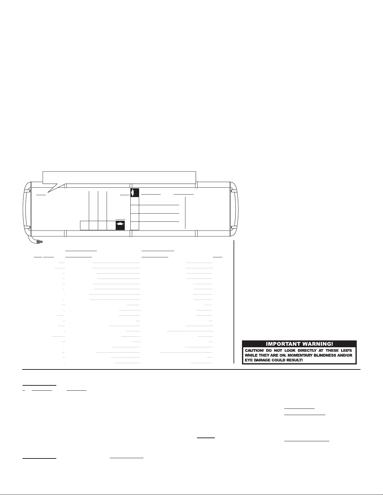
Installing Corner Linear-LED®
Lighthead into extrusion
Insert the tabs on the lighthead housing,
into the channels in the extrusion.
Insert the tabs on the lighthead housing,
into the channels in the extrusion.
Installing Lens and Lighthead
Housing into extrusion
Lens
fits
here
Top and bottom of extrusion
secure to Support Bracket.
SUPPORT
BRACKET
21
98
Accessing the Lightbar
5
4
6
7
RTD
5
1
Mounting Endcap
Endcap
Lens
Screw
REF REF
REF
1
1
111
1
1
1
1
1
1
1
1
1
1
1
1
1
A/R
212
1
A/R
1
2
1
1
2
1
2
1
A/R
1
2
1
111
66
2
2
4
10
1121
6
2
12
1
A/R A/R
A/R10A/R
12
8
1
8
1
A/R
A/R
12
8
1
1
A/RA/R A/R
A/RA/R A/R
8
6
1
2 2
1
6
1
2
4
A/R
A/R
1
1
4
4
A/R
A/R A/R
A/R
4
A/R
A/R
A/R
A/R
A/R
A/R
A/RA/R
A/R
A/R
A/R
A/R
A/R
A/R
A/R
A/R
A/R
A/R
A/R
A/R
A/R
A/R
A/R
A/R
A/RA/R
A/R
A/R
A/R A/R
A/R
A/R
A/R
A/R A/R
A/R
A/R
2
A/R4A/R
2
3
ITEM
PART NUMBER
DESCRIPTION
QTY QTY QTY
11
12
13
14
15
16
17
18
19
20
4
5
6
7
8
9
10
1
21
22
30
31
32
33
34
35
36
37
38
39
23
24
25
26
27
28
29
40
41
49
50
51
52
53
54
42
43
44
45
46
47
48
OVERMOLD ENDCAP CLEAR
02-036E683-30
01-0686402-
11-26B607-044
09-1363542-00
01-026B6938E0
01-026B6938D0
46-0986421-00
07-243170-000
46-0986413-00
01-026B855-30
02-036B855-00
46-0743903-17
01-0686402-
01-026B873-00
10-0522960-00
10-0322935-00
14-104286-16JB
14-104216-06J
38-0142783-00
11-483564-000
46-0786418-00
46-0986417-00
21-7263998-00
14-0023347-00
26-0115663-10
13-104111-063
46-0743196-17
21-11245004-1
01-0686402-
68-1983818-30
68-1963333C03
01-026B8272A0
01-026B8272D0
01-026B8272E0
01-026B8272J0
01-026B8272K0
01-026B8272M0
01-026B693210
01-026B693220
01-026B693230
01-026B693240
01-026B693250
01-026B693810
01-026B693820
01-026B693830
01-026B693850
01-026B693840
01-026B6938J0
11-363312-038
11-26B607-038
11-26B607-049
11-363312-044
11-363312-049
68-1983819-30
68-1963333C08
68-1983567-30
02-0342791-30
LFL Liberty™ 43.13" LC 2010
LFL Liberty™ 54.00" LC 2010
LFL Liberty™ 48.50" LC 2010
LR11 ALLEY LIGHT (WHT)
#10-24 X 1-1/4" TX. PHD. W/SHLDR
HARNESS, INBOARD SINGLE
END SUPPORT BRACKET
CABLE, 17/C 22GA (17')
ASS'Y, ELECTRONIC I/O
HARNESS, TD/WORK LIGHTS
HARNESS, CORNER LED
PLUG, VENT (3/4")
SCREW, 10-24 x 1.25" TX PHD
CABLE CLAMP, 5/8"
#10-24 WIZ NUT
GROMMET, 1.562"
INPUT CABLE, (2C-10GA.) 17'
TOP, EXTRUDED (44.00")
PANEL, FILLER
EXT CORNER 18LED W/R AMP
EXT CORNER 18LED B/W AMP
HARNESS, INBOARD DUAL
SPACER, CORNER
LABEL, MODEL & SERIAL NO.
INSULATOR, FOAM PAD
#10-24 X 3/8 PPH SCREW
LABEL, "FRONT" LTBAR ASS'Y.
HOUSING, LT HEAD (SNAP-IN)
SUB 500 12LED RED/WHT
EXT CORNER 18LED GRN AMP
EXT CORNER 18LED RED AMP
EXT CORNER 18LED B/R AMP
BASE, EXTRUDED (38.61")
TOP, EXTRUDED (38.61")
TOP, EXTRUDED (49.39")
BASE, EXTRUDED (44.00")
BASE, EXTRUDED (49.39")
LENS, 5.687" LG. (CLEAR)
LENS, 8.375" LG. (CLEAR)
ASS'Y., LENS DIVIDER (CLEAR)
LENS, 15.800" LG. (CLEAR)
SUB 500 12LED BLU/WHT
SUB 500 12LED RED/BLU
SUB 500 12LED AMB/RED
SUB 500 12LED AMB/BLU
EXT CORNER 12LED AMB AMP
EXT CORNER 12LED BLU AMP
EXT CORNER 12LED WHT AMP
EXT CORNER 12LED GRN AMP
EXT CORNER 12LED RED AMP
EXT CORNER 18LED AMB AMP
EXT CORNER 18LED BLU AMP
EXT CORNER 18LED WHT AMP
LENS, 5.062" LG. (CLEAR)
LENS, 10.500" LG. (CLEAR)
SUB 500 12LED AMB/AMB
Page 5
 Loading...