

Page 1

®
ENGINEERING COMPANY INC.
51 Winthrop Road
Chester, Connecticut 06412-0684
Liberty™ and Freedom™ LC Lightbars
Installation Guide:
Phone: (860) 526-9504
Fax: (860) 526-4078
Internet: www.whelen.com
Sales e-mail: autosale@whelen.com
Canadian Sales e-mail: canadiansales@whelen.com
Customer Service e-mail: custserv@whelen.com
Safety First
This document provides all the necessary information to allow your Whelen product to be properly and safely installed.
Before beginning the installation and/or operation of your new product, the installation technician and operator must
read this manual completely. Important information is contained herein that could prevent serious injury or damage.
• Proper installation of this product requires the installer to have a good understanding of automotive electronics,
systems and procedures.
• Failure to use specified installation parts and/or hardware will void the product warranty!
• If mounting this product requires drilling holes, the installer MUST be sure that no vehicle components or other
vital parts could be damaged by the drilling process. Check both sides of the mounting surface before drilling
begins. Also de-burr any holes and remove any metal shards or remnants. Install grommets into all wire
passage holes.
• If this manual states that this product may be mounted with suction cups, magnets, tape or Velcro®, clean the
mounting surface with a 50/50 mix of isopropyl alcohol and water and dry thoroughly.
• Do not install this product or route any wires in the deployment area of your air bag. Equipment mounted or
located in the air bag deployment area will damage or reduce the effectiveness of the air bag, or become a
projectile that could cause serious personal injury or death. Refer to your vehicle owner’s manual for the air bag
deployment area. The User/Installer assumes full responsibility to determine proper mounting location, based
on providing ultimate safety to all passengers inside the vehicle.
• For this product to operate at optimum efficiency, a good electrical connection to chassis ground must be
made. The recommended procedure requires the product ground wire to be connected directly to the NEGATIVE
(-) battery post.
• If this product uses a remote device to activate or control this product, make sure that this control is located in
an area that allows both the vehicle and the control to be operated safely in any driving condition.
• Do not attempt to activate or control this device in a hazardous driving situation.
• This product contains either strobe light(s), halogen light(s), high-intensity LEDs or a combination of these
lights. Do not stare directly into these lights. Momentary blindness and/or eye damage could result.
• Use only soap and water to clean the outer lens. Use of other chemicals could result in premature lens cracking
(crazing) and discoloration. Lenses in this condition have significantly reduced effectiveness and should be
replaced immediately. Inspect and operate this product regularly to confirm its proper operation and mounting
condition. Do not use a pressure washer to clean this product.
• It is recommended that these instructions be stored in a safe place and referred to when performing
maintenance and/or reinstallation of this product.
• FAILURE TO FOLLOW THESE SAFETY PRECAUTIONS AND INSTRUCTIONS COULD RESULT IN DAMAGE TO
THE PRODUCT OR VEHICLE AND/OR SERIOUS INJURY TO YOU AND YOUR PASSENGERS!
Automotive: Lightbars
For warranty information regarding this product, visit www.whelen.com/warranty
©2003 Whelen Engineering Company Inc.
Form No.13745U (081010)
Page 1
Page 2

Insert foot into extrusion with locking plate
attached.
Twist mounting foot into
position
ANCHOR
PLATE
Loosely secure foot and locking plate.
IMPORTANT! The lightbar should be a minimum
Mounting
Pad
Adjustable
Mounting
Foot
Washer
Nut
Mounting
Foot
Base
Standard
Mounting
Foot
Mounting
Pad
Washer
Nut
Locking
Plate
Bolt
Bolt
of 16" from any radio antennas!
Permanent Mounting:
1. Locate the mounting foot, anchor plate and locking plate included with your
lightbar. If not already present, install the locking plate onto the mounting
foot. When properly positioned, this plate is centered from side-to-side on
the mounting foot.
2. Flip the lightbar upside-down to expose the bottom of the extrusion and
place the mounting foot onto the extrusion.
3. Rotate the mounting foot 90° counter-clockwise. Make sure that the edges
of the mounting foot swing into position under the extrusion mounting lip.
Install an anchor plate onto the extrusion in the same manner.
4. Repeat this procedure for the remaining mounting foot and anchor plate
and return the lightbar to its right side-up position.
5. Position the lightbar onto the vehicle roof in the desired mounting location.
One often selected location is directly above the B-pillars. This area is the
strongest part of the roof. Refer to your lightbar manual for cable exit
location, to be sure that the lightbar is facing the proper direction.
6. Adjust the two mounting feet outwards so that they are as close to the
edge of the roof as possible. Both mounting feet must be in full contact with
the roof. Be sure that there is no less than 1/2” clearance between roof and
lightbar at their closest point. When the mounting feet are in their proper
position, lightly tighten the locking plate allen head set screws.
7. Return the lightbar to an upside-down position. Slide each anchor plate
outwards until it is fully engaged with its corresponding mounting foot. With
the mounting feet and anchor plates in their proper positions firmly tighten
all of the set screws (2 or 4 per side). Flip the lightbar right side-up and
return it to its mounting position.
8. Open both drivers side doors. In the area directly below the mounting foot,
pull the weather-strip away from the vehicle so the area where the
mounting strap will be secured is exposed. Repeat for the other side.
9. Insert the mounting strap through the mounting foot. Be sure that the strap
fits flush against the area where it will be secured onto the vehicle. Insert
the tension bolt through the mounting strap and anchor plate, into the
tinnerman nut. Tighten slightly with a long-shafted, Phillips screwdriver.
Repeat procedure for passenger side.
10. If your mounting strap has mounting holes in the end of the strap, use
these holes as a template to drill appropriately sized pilot holes through the
strap and into the vehicle. Repeat for passenger side of the vehicle.
11. Firmly tighten the tension bolts to secure the lightbar to the vehicle.
Strap Mounting:
1. Locate the mounting foot, anchor plate and locking plate included with your
lightbar. If not already present, install the locking plate onto the mounting
foot. When properly positioned, this plate is centered from side-to-side on
the mounting foot.
2. Flip the lightbar upside-down to expose the bottom of the extrusion and
place the mounting foot onto the extrusion.
3. Rotate the mounting foot 90° in a counter-clockwise direction. Make sure
that the edges of the mounting foot swing into position under the extrusion
mounting lip. Install an anchor plate onto the extrusion in the same
manner.
4. Repeat this procedure for the remaining mounting foot and anchor plate
and return the lightbar to its right side-up position.
5. Position the lightbar onto the vehicle roof in the desired mounting location.
One often selected location is directly above the B-pillars. This area is the
strongest part of the roof. Refer to your lightbar manual for cable exit
location, to be sure that the lightbar is facing the proper direction.
6. Adjust the two mounting feet outwards so that they are as close to the
edge of the roof as possible. Both mounting feet must be in full contact with
the roof. Be sure that there is no less than 1/2” clearance between roof and
lightbar at their closest point. When the mounting feet are in their proper
position, lightly tighten the locking plate allen head set screws.
7. Return the lightbar to an upside-down position. Slide each anchor plate
outwards until it is fully engaged with its corresponding mounting foot. With
the mounting feet and anchor plates in their proper positions firmly tighten
all of the set screws (2 or 4 per side). Flip the lightbar right side-up and
return it to its mounting position.
8. Open both drivers side doors. In the area directly below the mounting foot,
pull the weather-strip away from the vehicle so the area where the
mounting strap will be secured is exposed. Repeat for the other side.
9. Insert the mounting strap through the mounting foot. Be sure that the strap
fits flush against the area where it will be secured onto the vehicle. Insert
the tension bolt through the mounting strap and anchor plate, into the
tinnerman nut. Tighten slightly with a long-shafted, Phillips screwdriver.
Repeat procedure for passenger side.
10. If your mounting strap has mounting holes in the end of the strap, use
these holes as a template to drill appropriately sized pilot holes through the
strap and into the vehicle. Repeat for passenger side of the vehicle.
11. Firmly tighten the tension bolts to secure lightbar to vehicle.
Page 2
Page 3

NOTE: Unless otherwise specified, the
lightbar mounting feet must be sitting as
close to the edge of the roof as possible.
Mounting feet must also be in full contact
with the roof and not be hanging off
the edge.
IMPORTANT: For strap mounted bars, be sure you have the right
sized lightbar for your vehicle. The lightbar should be about the
same width as the vehicle roof. If the
lightbar is too large or small it will not
mount properly to the vehicle and
may shift or come loose during driving.
1/2" Minimum Clearance at Closest Point
MOUNTING FOOT
TINNERMAN
NUT
FOOT
ANCHOR
PLATE
SET
SCREW
Plate slides into
lightbar extrusion
5" Mounting Foot
NUT
BOLT
SPLIT LOCK
WASHER
METAL SCREW
NOTE: The mounting straps are made to fit the contours of individual
vehicles. The strap
may look different. If your lightbar has a 5"
mounting foot, it will assemble differently than the standard
mounting foot. It also uses an extension to compensate for
the extra height. Follow these illustrations for assembly.
Mounting to the lightbar is the same.
shown here is for example only. The strap
for your vehicle
NOTE:
NOTE:
NOTE:
NOTE:
NOTE:
NOTE:
STRAP
SHEET
METAL
SCREWS
EXTENSION
VEHICLE ROOF
Locking
Plate
Mounting
Foot
Nut
Mounting
Pad
Adjustment
screws
Lock
Washer
Anchor Plate
Tinnerman
Nut
Tinnerman
Nut
Anchor
Plate
Locking
Plate
Mounting Strap
Mounting
Screw
Adjustable Foot
Model MKAJ
Standard Foot
Model MKEZ
Mounting
Strap
Mounting
Screw
Tension
Bolt
Tension
Bolt
Tighten screws
with torque wrench
set at 35 to 40 in/lbs
Model
MKAJ
Mounting
Foot
Allen
screws
Mounting
Foot Base
NOTE: Model MKAJ is an adjustable mounting foot. On this model you
DRILLING THE CABLE ACCESS HOLE
Drill cable access hole in appropriate area
for your lightbar (see note)
FRONT OF LIGHTBAR
For
cables exiting
the Driver-side
of the extrusion
lightbars
with
For
cables exiting
the Passenger-side
of the extrusion
lightbars
with
may loosen the screws on the rear of the foot and adjust the angle of the
lightbar. This feature can be used if the angle of the roof is not level with
the road.
IMPORTANT: To adjust the leveling screws you must use a torque wrench
set at 35 to 40 in./lbs.
Routing your Lightbar Cable(s)
1. To protect the headliner from damage caused by drilling the cable access
hole through the vehicle roof, allow a 5” to 7” distance between roof and
headliner by lowering the headliner before drilling.
WARNING! There may be a roof support member that spans the
distance between the driver’s and passenger’s side. DO NOT DRILL
THROUGH THIS MEMBER! Adjust the location until the hole can be
drilled without contacting this support member.
2. Using a 1” hole saw, drill the cable access hole. Use a round file to smooth
and de-burr the edges than insert a 1” grommet.
3. Insert the cable(s) through the cable access hole into the vehicle. Use
RTV silicone to weatherproof the access hole after the cable(s) are pulled
completely into the vehicle.
4. Route the cable(s) through the vehicle following manufacturers
recommendations.
WARNING: Many vehicles are now equipped with side curtain and Bpillar air bags. Alternate routing may be required.
Page 3
Page 4

Connecting the Cables:
WARNING! All Customer supplied wires that connect to the positive
terminal of the battery must be sized to supply at least 125% of the
maximum operating current and FUSED
load. DO NOT USE CIRCUIT BREAKERS WITH THIS PRODUCT!
at the battery to carry that
Level Mode: Applying +12 VDC voltage to the VIOLET wire for more than 1
second holds the lightbar in low power mode until voltage is removed (a toggle
switch is preferred).
IMPORTANT NOTE: The corner modules in your lightbar do not
switch to low power when this option is applied. They will always
remain in normal high power.
Power Cable:
1. Open the wiring shield lid and route the power cable into the wiring shield
and towards the firewall. Make sure you do not to pinch or crush any
wires when running them through the wire shield.
2. Follow the factory wiring harness through the firewall. It may be
necessary to drill a hole in the firewall. If so, be absolutely sure that there
are no components that could be damaged by drilling. After the hole has
been drilled, insert a grommet to protect the cable.
3. Route the cable along the factory wiring harness to the battery.
4. Install a 30 amp fuse block (customer supplied) on the end of the RED
wire in the power cable. Remove the fuse from the fuse block before
connecting any wires to the battery.
5. Connect the fuse block to the POSITIVE (+) terminal on the battery. There
can not be more than two feet of wire between the fuse block and the
battery. The wire between the fuse block and the battery is “unprotected”,
do not allow this wire to touch any other wires.
6. Connect the BLACK wire to the factory chassis ground.
Cruise Lights & AUX (WHITE/ORANGE):
The WHITE/ORANGE wire operates in one of 3 different modes. Selecting a
mode is controlled with the Scan-Lock™ wire. Using Scan-Lock™ (See ScanLock™), change between the 3 available modes as though you were changing
flash patterns. The three modes are as follows:
MODE 1 (Default) - Cruise Lights in Low Power and the AUX port is activated.
MODE 2 - Cruise Lights in High Power and the AUX port is activated.
MODE 3 - Cruise Lights are not activated and the AUX port is activated.
Hi/Low Power (VIOLET):
The type of switch used is dependant on how the operator wishes the Hi/Low
feature to function:
Latching Mode: By applying +12 VDC voltage to the VIOLET wire for less than
1 second, the lightbar is “latched” into low power operation. The unit must be
turned off and then back on to restore normal, high power operation (a
momentary switch is preferred).
Scan-Lock™ (WHITE/VIOLET):
TO CYCLE FORWARD THROUGH AVAILABLE PATTERNS: Activate ONLY
the control wire of the function you wish to effect and apply +12 volts to the
Scan-Lock™ wire (WHITE/VIOLET) for less than 1 second and release. This
will change the pattern. For example, to change the Front Outboard LED
pattern, apply +12VDC to the GREEN/WHITE wire and then momentarily apply
+12VDC to the WHITE/VIOLET wire. Repeat until the desired pattern is
displayed. Let this pattern run for 5 seconds to configure it as the pattern the
Front Outboard LEDs will display when activated. Important: Only ONE
function may be active while changing patterns. Repeat for next pattern.
TO CHOOSE A PATTERN: Allowing the desired pattern to run for more than 5
seconds makes it the default pattern.
TO RESET TO THE FACTORY DEFAULT PATTERN: Turn o ff all lightbar
functions. Apply +12 volts to the Scan-lock™ wire and turn the appropriate
function back on and it is now restored to its factory default pattern.
Available Flash Patterns:
Front Corner, Rear Corner, Outboard
Inboard and Center
1. SignalAlert™ 75
2. CometFlash® 75
3. DoubleFlash 150
4. DoubleFlash 75
5. SingleFlash 375
6. SingleFlash 150
7. SingleFlash 75
8. ActionFlash™ 150
9. ModuFlash™
10. ActionScan™
Front Outboard, Inboard and Center
1. SignalAlert™ 75
2. CometFlash® 75
3. DoubleFlash 150
4. DoubleFlash 75
5. SingleFlash 375
6. SingleFlash 150
7. SingleFlash 75
8. ActionFlash™ 150
9. ModuFlash™
10. Steady/SF75
11. Steady/Steady
12. ActionScan™
Take-Down / Alley
1. T-D & Alley - SingleFlash 240 ALT
2. T-D & Alley - DoubleFlash 120 ALT
3. T-D only - SingleFlash 240 SIM
4. T-D only - DoubleFlash 120 SIM
Traffic Advisor™ Sequence
1. Seq to Solid
2. Seq On - Seq Off
3. One Lamp Triple
4. Two Lamp Triple
Control Cable: Extend the control cable to your switch panel and make your connections using the information provided. The control cable connects
to your control head or switch box and is fused there. Applying +12VDC to a control wire activates its function. Fuse as noted below.
Wire Color Function Fuse
GREEN . . . . . .Front Corner LEDs . . . . . . 1 AMP
BLUE . . . . . . .Rear Corner LEDs . . . . . . 1 AMP
GRN/WHT . . . .Front Outboard LEDs . . . . 1 AMP
BLU/WHT . . . .Rear Outboard LEDs . . . . 1 AMP
GRN/BLK . . . .Front Inboard LEDs . . . . . 1 AMP
BLU/BLK . . . .Rear Inboard LEDs . . . . . 1 AMP
Special Order Lightbars:
Unicor Lightbar:
Wire Color Function Fuse
GREEN . . . . All Front LEDs . . . . . . . . . . . . 1 AMP
BLUE . . . . . Rear LEDs / RED-BLUE . . . . 1 AMP
VIOLET . . . . Flashing Ctr RED & Alleys . . . 1 AMP
ORANGE . . Take Downs . . . . . . . . . . . . . . 1 AMP
GREY . . . . . Rear AMBER . . . . . . . . . . . . . 1 AMP
YELLOW. . . Passenger Alley . . . . . . . . . . . 1 AMP
WHITE . . . .Driver Alley . . . . . . . . . . . . . . . 1 AMP
WHT/BLK . .Steady Center RED . . . . . . . . 1 AMP
WHT/GRN. . . Right TA . . . . . . . . . . . . . . 1 AMP
WHT/BLU . . . Flashing Alley & T.D.’s . . . 1 AMP
YELLOW . . . Pass.-Side Alley Lights . . . 1 AMP
WHITE . . . . . Driver-Side Alley Lights. . . 1 AMP
WHT/BLK . . . Take-Down Lights . . . . . . . 1 AMP
WHT/ORG . . Cruise Lights & AUX . . . . . 1 AMP
WHT/YEL . . . . . Left TA . . . . . . . . . . . . . 1 AMP
Philadelphia Lightbar:
BLU/BLK . . . End External Pods . . . . . . . 1 AMP
WHT/RED. . . Front External Pods . . . . . . 1 AMP
WHT/BRN . . Rear External Pods . . . . . . . 1 AMP
YELLOW . . . Passenger Alleys . . . . . . . . 1 AMP
WHITE . . . . . Driver Side Alleys . . . . . . . . 1 AMP
GREEN. . . . . Front Corners . . . . . . . . . . . 1 AMP
BLUE . . . . . . Rear Corners . . . . . . . . . . . 1 AMP
GRN/WHT . . Front Outboards . . . . . . . . . 1 AMP
BLU/WHT. . . Rear Outboards . . . . . . . . . 1 AMP
GRN/BLK . . . Front Outboards . . . . . . . . . 1 AMP
WHT/BLU. . . Flashing Alley & TDs. . . . . . 1 AMP
Page 4
WHT/BRN . . . . . Rear Center LEDs . . . 1 AMP
VIOLET . . . . . . .Hi/Low Power . . . . 0.5 AMPS
WHT-VIO . . . . . . Scan-Lock™. . . . . . 0.5 AMPS
WHT/RED. . . . . . Front Center LEDs . . . 1 AMP
NONE . . . . . . . . . RFI shield drain / to ground
Activating WHT/GRN + WHT/YEL = Split TA
WHT/BLK . . TakeDowns. . . . . . . . . . . . . 1 AMP
WHT/ORG . . . . Cruise Lts. & AUX . . . . . . 1 AMP
VIOLET . . . . . . Hi-Low Power . . . . . . . . 0.5 AMP
WHT/VIO . . . . . Scan-Lock™ . . . . . . . . . 0.5 AMP
WHT/GRN . . . . Right TA. . . . . . . . . . . . . . 1 AMP
WHT/YEL. . . . . Left TA . . . . . . . . . . . . . . . 1 AMP
Activating WHT/GRN + WHT/YEL = Split TA
Leader Lightbar:
GREEN . . . . . . Front Corner LEDs. . . . . . 1 AMP
GRN/WHT . . . . Front Outboards. . . . . . . . 1 AMP
GRN/BLK. . . . . Front Inboards . . . . . . . . . 1 AMP
WHT/RED . . . . Front Center LEDs . . . . . . 1 AMP
Page 5

Lighthead mounting holes
snap into the raised bosses
on the lighthead bracket.
Ears on lighthead bracket
slide into channels in
extrusion (base).
Snap lighthead
into bracket.
Endcap & Gasket
500 Series Alley Light
Mounting Lightheads to Extrusion
If lightbar has
no alley light,
use nuts to
hold lens in.
Halogen Lighthead
slides into extrusion here.
BASE
EXTRUSION
LR-11 Take-down and Alley Light
LR-11 Alley Light
Endcap
Lens
Screw
BASE EXTRUSION SIDE VIEW
LIGHTHEAD
Endcap, Gasket , Lenses & Spacers Installation
Gasket & Halogen Alley Light
BARB
BOSS
Halogen Lighthead
snaps into extrusion
Align lighthead
reflector up with 4
bosses in endcap.
Press reflector into
place.
Endcap with integrated gasket
Servicing: Liberty Lightbar
Servicing: Freedom™ Lightbar
Halogen Alley Light
Remove the screws (A) that hold the endcap on and pull the endcap and gasket (C) off.4 (B) Slide lenses
(D) out of the lightbar, to gain access to the extrusion. When reinstalling the lenses and spacers, install the
cord seal (NFPA / See below). When reinstalling the endcap, place the endcap gasket into it's position on
the endcap and line up all the tabs and holes. Spacers (not shown) mount the same as lenses.
D
D
C
Insert cord seal into track in lens
A
B
Seal Cord Installation / NFPA Only:
Cut the seal cord approx. 1-1/2" longer than the extrusion on each side.
Rub silicone over the cord seal leaving 3 to 4 inches on one end dry.
Begining with 1 corner lens, start the lens into the bottom
lens track. Place the cord seal onto the groove in the
top of the lens eav 1 to 2 inches
Hold onto the left end of the seal hanging
out and slide the corner lens into
position.
1 2 3 -
4 -
3 3 -
4 4 -
. L e free.
Inspect seal cord for any areas that have wrinkled.
Especially in the areas around the dividers.
Push the lenses together tight and trim excess seal
cord at each end.
6 -
7 -
6 -
7 -
From the opposite end of the
lightbar, pull the seal
cord tight and install
the remaining lenses
and divider.
5 -
5 5 5 5 -
NOTE: Lens dividers must
be installed as each lens is
put into position
Installing Corner Linear-LED®
Insert the tabs on the lighthead housing, into the channels in the extrusion.
Installing Lens and Lighthead
Lens
fits
here
Extrusion secures to Support Bracket.
SUPPORT
BRACKET
BASE EXTRUSION
SUPPORT
BRACKET
SECURE TO
EXTRUSION
TO SECURE
BRACKET
EXTRUSION
LR11 TAKEDOWN
LR11
ALLEY
LIGHT
BASE
EXTRUSION
LR-11 Take-down
A
D
J
U
S
T
A
N
G
L
E
Secure lighthead
bracket to extrusion
Snap lighthead
bracket into TD
bracket
Slide into
tracks in
extrusion
Page 5
Page 6
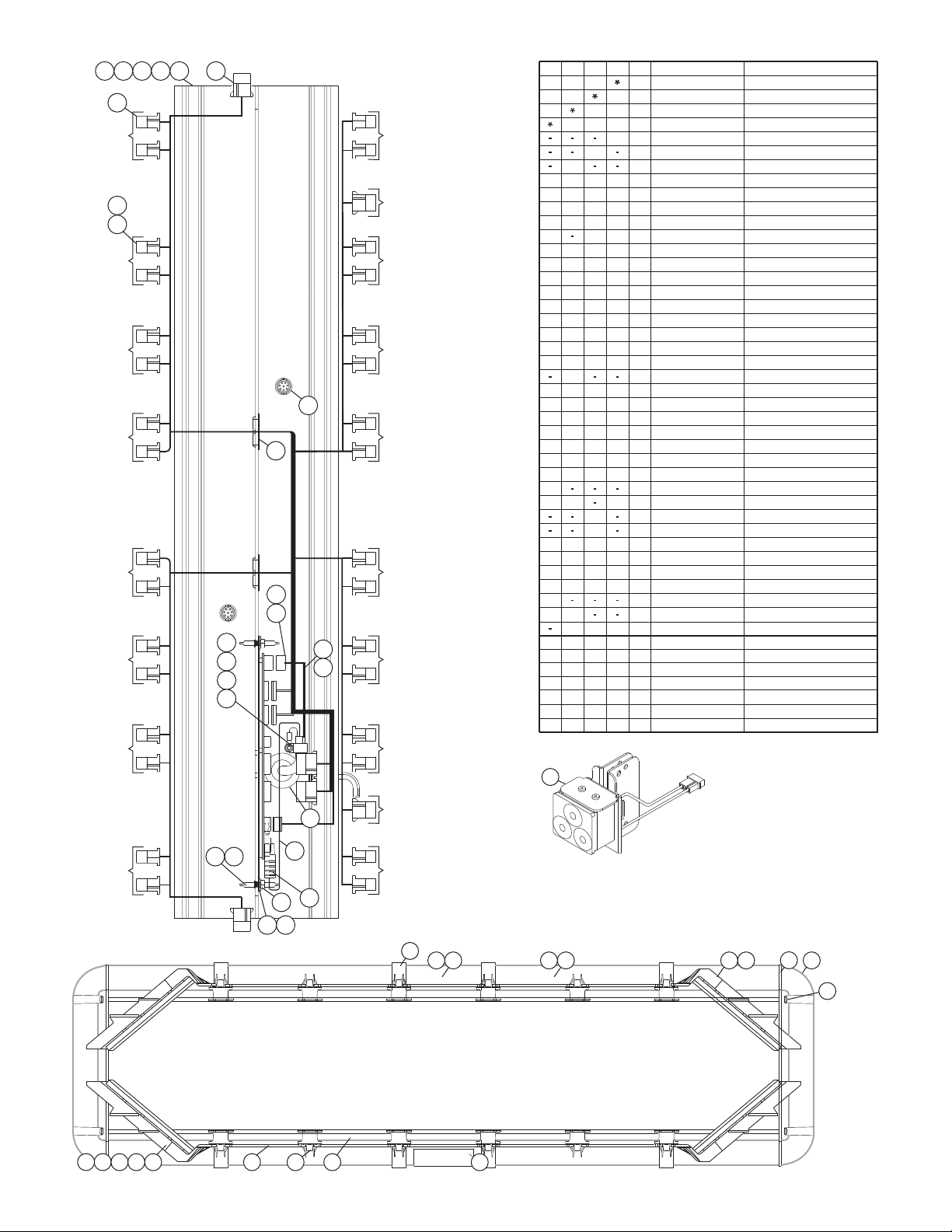
BROWN
REAR LED 1
BROWN
FRONT LED 1
BROWN
WHT/BRN
GRAY
ORANGE
WHT/ORG
GREEN
FRONT LED 5
YELLOW
FRONT LED 4
ORANGE
FRONT LED 3
RED
FRONT LED 2
REAR OF LIGHTBAR
BLUE
REAR LED 6
GREEN
REAR LED 5
YELLOW
REAR LED 4
ORANGE
REAR LED 3
RED
REAR LED 2
DRIVER'S
SIDE
PASSENGER
SIDE
YELLOW
WHT/YEL
WHITE /
BLACK
WHT
RED
WHT/RED
YELLOW
46
123
24
38
37
9
21
22
5
29
7
14
27
10
6
36
18
17
16
204
BLUE
FRONT LED 6
FRONT
11
35
34
31
32
3940
3930
45 3344
42
25
43
41
26
47
13
19
15
23
12
LR11 ALLEY
28
ITEM
PART NUMBER
DESCRIPTION
QTY QTY QTY QTY
1 1
1
1
2
2
1
212
1
212
1
1
2
3
2
4
2
1
1
5
6
7
1 14111
2
1
8188
2
1
1
11
8
11
2
1
9
10
1 12
4
2
1
1
111
1
242
4
1
11617
2
4
18
20
#10-24 x 1-1/4" TX. PHD. SCREW W/SHLDR
NUT, 1/4-20 ELASTIC STOP (316 SS)
BASE EXTRUSION (45.75")
BASE EXTRUSION (51.125")
BASE EXTRUSION (56.50")
MTG. STUD
BUSHING, 1-5/8"
CABLE, 2/C 10GA 17'
CABLE, 17/C 22GA 17'
HARNESS, 6 LIGHT
GROMMET, 1.562"
NUT, #10-24 WHIZ
CABLE CLAMP, 5/8"
PROTECTIVE COVER
HOUSING, 3 POS SOCKET
ASSEMBLY, I/O BOARD LC
A/RA/R A/R A/R
271111
1
6
12
18
11
2
8
2
2
8
12
101816
1 24
22
6
22
21
23
14
12
25
26
A/R
4
4
2
A/R1A/R
1
4 4
30
A/R
11
28
29
44
31
32
33
2
1
2
1
2
2
1
2
2
1
1
141
2
2
2
1
35
34
36
1
38
37
39
4
44
40
1111
HARNESS, ALLEY LIGHT
SINGLE LR11 ALLEY FREEDOM
HOUSING, 16 POS SCKT. CMNL
VENT, 3/4"
6 LIGHT HARNESS 60"
LENS, 5.00" CLEAR
LENS DIVIDER ASS'Y. (CLEAR)
LABEL, MODEL & SERIAL NO.
#10-24 x 1 PPHMS
FILLER PANEL, "400" SERIES
MOUNTING BRACKET
BRACKET, SPACER
LENS, 6.562" CLEAR
LENS, 9.25" CLEAR
CORNER REFLECTOR LED BLUE
CORNER REFLECTOR LED RED
HARNESS, 4 LIGHT 72"
LENS, 15.75" CLEAR
LENS, 10.375" CLEAR
BASE EXTRUSION (40.375")
HOUSING, 2 POLE
GASKET, ENDCAP
ENDCAP, CLEAR
LABEL, "FRONT"
Freedom™ Ext LC R/R/B/B 44"
Freedom™ Ext LC R/R/B/B 50"
Freedom™ Ext LC R/R/B/B 55"
Freedom™ Ext LC R/R/B/B 60"
42
45
46
47
11-363141-000
46-0742883-17
46-0742957-17
21-242401-000
22-0542701-00
11-363143-000
11-363142-000
26-0115663-10
13-104111-063
14-104286-16JB
21-11245004-1
46-0763941-00
01-0269881-00
39-0403023-04
22-0416982-00
13-130111-072
46-0763967-00
07-242815-000
14-104216-160
07-263103-000
09-1363158-00
10-0523067-02
02-0341448-30
46-0784223-00
21-7263998-00
68-1984104-30
68-1983817-30
68-1983816-30
01-026C368-30
39-0416323-04
68-1183369-30
38-0283381-00
39-0017188-08
11-363390-000
68-1183491C02
46-0763942-00
68-1984105-30
01-026B805550
01-026B805220
10-0322935-00
01-0684466-
01-0684466-
01-0684466-
01-0684466-
CORNER REFLECTOR LED AMBER
41
01-026B805110
CORNER REFLECTOR LED GREEN
44
01-026B805440
CORNER REFLECTOR LED WHITE
43
01-026B805330
A/RA/R A/R A/R
A/RA/R A/R A/R
A/RA/R A/R A/R
A/RA/R A/R A/R
A/RA/R A/R A/R
Page 6
Page 7

I.O. CARD ASSEMBLY
("LC" SERIES)
TD
ALLEY AUX
REAR FRONT
3 POS. CONN.
P1P2P3-
WHT-YEL
WHT-GRN
N/C
Cable EXIT
16 POS. CONN.
VIO
GRN-BLK
GRN-WHT
BLU-BLK
WHT-BLU
WHT-ORG
WHT-VIO
WHT-RED
P1P2P3P4P5P6P7P8-
P9- GRN
P10P11P12P13P14P15P16-
WHT-BRN
BLU-WHT
YEL
BLU
WHT
SHIELD
WHT-BLK
INPUT
CABLE
DETAIL
12
1
2
3
30
6
10
75
73
32
58 59
60 61
57
62
16
17
39
51
55.125
3726
43
11
38
FRONT
35
60.500
FRONT
26
37
38
34
43
42
49.750
FRONT
34
43
26
37
36
11
38
11
FRONT
44.375
34
42
26
37
38
33
48
BLU / REAR LED 6 GRN / REAR LED 5 YEL / REAR LED 4 ORG / REAR LED 3
YEL
WHT
40
BRN
ORG
YEL
RED
292929292929
40
29
18
4
29
29
29 29
5
8 9
44
45 46
RED
48
BRN
ORG
RT
YEL
49
RED / REAR LED 2 BRN / REAR LED 1
YEL / FRONT LED 4
ORG / FRONT LED 3 RED / FRONT LED 2 BRN / FRONT LED 3
56
BLU / FRONT LED 6 GRN / FRONT LED 5
GRY
WHT/
BLK
29
2
3
ITEM
PART NUMBER
DESCRIPTION
QTY QTY QTY QTY
11
12
14
4
5
6
7
8
9
10
1
01-0684194-03
01-026B807-20
01-026B807-50
26-0115663-10
13-104111-063
14-104286-16JB
21-11245004-1
46-0742883-17
46-0742957-17
21-242401-000
22-0542701-00
11-363143-000
11-363142-000
11-363141-000
01-0684194-18
01-0684194-13
01-0684194-08
2222
1
1
2
4
1
1
212
4
111
4
1
2
1
4
1
1111
2
1
8
1
88
212
1
11
8
2
1
1
Freedom™ Gen 3 LC R/R/B/B 44"
Freedom™ Gen 3 LC R/R/B/B 60"
Freedom™ Gen 3 LC R/R/B/B 55"
Freedom™ Gen 3 LC R/R/B/B 50"
#10-24 x 1-1/4" TX. PHD. SCREW-SHLDR
CORNER REFLECT. LED RED
CABLE, 17/C 22GA 17'
CABLE, 2/C 10GA 17'
BUSHING, 1-5/8"
MTG. STUD
BASE EXTRUSION (56.50")
BASE EXTRUSION (51.125")
BASE EXTRUSION (45.75")
CORNER REFLECT. LED BLU
CABLE CLAMP, 5/8"
NUT, #10-24 WHIZ
GROMMET, 1.562"
NUT, 1/4-20 ELASTIC STOP (316 SS)
16
17
18
26
27
28
29
30
31
20
21
22
23
24
25
32
33
34
35
01-0269881-00
39-0403023-04
22-0416982-00
13-130111-072
1
1
2
4
111
1
242
4
1
1
2
4
ASSEMBLY, I/O BOARD LC
HOUSING, 3 POS SOCKET
PROTECTIVE COVER
01-0286361244
01-0286361211
01-0286361233
01-0286361255
68-1983816-30
68-1983817-30
68-1984104-30
02-0341448-30
10-0523067-02
01-0286361222
20-0042765-00
14-104216-160
02-0363189-00
09-1363158-00
07-263103-000
1111
A/R
6
A/R
A/R
A/R
A/R
A/R A/R
A/R
A/R
A/R
A/R
A/R
A/R
A/R8A/R
8
A/R
A/R
A/R
A/R
A/R
6
4
12
A/R
18
11
12
101816
A/R
4
2
A/R
4
11
14
12
A/R
4
4
4
4 4
LINEAR LED 400 GRN GEN III AMP
LENS, 5.00" CLEAR
LENS DIVIDER ASS'Y. (CLR)
LABEL, MODEL & SERIAL NO.
LINEAR LED 400 AMB GEN III AMP
LINEAR LED 400 WHT GEN III AMP
LINEAR LED 400 RED GEN III AMP
LINEAR LED 400 BLU GEN III AMP
SPACER, CORNER STROBE
#10-24 x 1 PPHMS
REFLECTOR 400 HALOGEN
FILLER PANEL, "400" SERIES
MTG BRACKET
LENS, 6.562" CLEAR
LENS, 9.25" CLEAR
36
07-242815-0004BRACKET, SPACER
37
38-0283381-00
222 2
GASKET, ENDCAP
41
42
43
38
39
40
48
49
50
51
59
60
61
62
63
64
65
66
52
53
54
55
56
57
58
A/RA/RA/RA/R
A/R
A/RA/R
A/R A/R
A/R A/R
A/R
A/RA/RA/R A/R
A/R
A/R
A/R
A/R
A/R
A/R
A/R
A/R
A/R
A/R
A/R
A/RA/R
A/R
A/R
A/R
A/R
A/R
A/R
A/R
A/R
A/R
A/R
A/R
A/R
A/R
A/R
A/R
A/R
A/R
A/R
A/R
A/R
A/RA/R
A/R
A/R
A/R A/R
A/R
A/R
A/R
A/R A/R
A/R
A/R
A/R
A/R
A/R
A/R
A/R
A/R
A/R
A/RA/R
A/R
A/R A/R
A/R
A/R A/R
TIR3 LED STDY BLU VERT AMP
02-036B4942B2
TIR3 LED STDY AMB VERTAMP
SUB ASSY, MR11/TIR3 ALLEY
02-036B4942A2
02-0364229-00
SUB ASY, DUAL LR11 ALLEY 100lm
SUB ASY, DUAL LR11 TD 100lm
LED 400 SPLIT 3/3 GEN III AMB/NONE/AMP
LED 400 SPLIT 6/3 GEN III RED/AMB/AMP
LED 400 SPLIT 6/3 GEN III BLU/AMB/AMP
LED 400 SPLIT 3/3 GEN III AMB/RED/AMP
LED 400 SPLIT 3/3 GEN III AMB/BLU/AMP
LED 400 SPLIT 6/6 GEN III AMB/RED/AMP
LED 400 SPLIT 6/6 GEN III AMB/WHT/AMP
LED 400 SPLIT 6/6 GEN III AMB/BLU/AMP
LED 400 SPLIT 6/6 GEN III AMB/NONE/AMP
TIR3 LED STDY WHT VERT AMP
TIR3 LED STDY RED VERT AMP
01-028636125A
6 LIGHT HARNESS 60"
HARNESS "Y"
01-0286361212
01-0286361210
46-0784223-00
02-036B4942C2
02-036B4942R2
46-0722108-00
01-02863612A0
01-028636122A
01-02863612AR
01-02863612AB
01-0286361215
01-0286361213
SUB ASY, DUAL LR11 ALLEY
SUB ASSY, DUAL LR11 TD
01-026B047-31
01-026B047-30
01-026A936-01
01-026A936-00
46-0743719-00
46-0763967-01
46-0741346-17
46-0743106-00
21-7263998-00
39-0416323-04
46-0763967-00
46-0763941-00
46-0763942-00
68-1984105-30
68-1183491C02
11-363390-000
39-0017188-08
68-1183369-30
1
2212
1
2
1
1
44
1
1
4
1
2
4
1
A/RA/RA/R A/R
A/R
2
1
A/R
A/R
A/R A/R
A/R
1
A/R
2
1
A/R
2
A/R
A/R
1
A/R
2
A/R
A/R
A/R
A/R
A/R
A/R
A/R
A/R
A/R
A/R
A/R
A/R
HARNESS, 4 LIGHT 72"
LENS, 15.75" CLEAR
LENS, 10.375" CLEAR
BASE EXTRUSION (40.375")
HOUSING, 2 POLE
ENDCAP, CLEAR
HARNESS, "Y" LR11
HARNESS, TAKE DOWN
HOUSING, 12 POS CMNL
CABLE, 9/C 17'
HARNESS, TA
VENT, 3/4"
HOUS., 16 POS SCKT CMNL
HARNESS, ALLEY LIGHT
HARNESS, 6 LIGHT
39-0412014-14
71
72
73
74
75
76
67
68
69
70
Rear of Lightbar
69-72 64-68
21-25
11
14
74
76
28
63
20
7 54
41
Page 7
Page 8

DRIVER
PASSNGR
81 83
31
62
42
38
41
33
61
35
40
59
58
36
FRONT OF LIGHTBARFRONT OF LIGHTBAR
BRN
ORG
BROWN
LED 1
RED
LED 2
ORANGE
LED 3
FRONT LED 1
BROWN
FRONT LED 2
RED
FRONT LED 3
ORANGE
YELLOW
LED 4
GREEN
LED 5
BLUE
LED 6
FRONT LED 4
YELLOW
FRONT LED 5
GREEN
FRONT LED 6
BLUE
YEL
21
ENDCAP
LED
BRN
ORANGE
15
YEL
RED
FRONT
I.O. CARD ASSEMBLY
("LC" SERIES)
REAR
IAL
ITD
57
67
5614
18
37
84
23702471257226736674687869
79
20
43
67
43
17
FRONT OF 54" LIGHTBARFRONT OF 54" LIGHTBAR
RA
LTD
YEL
RED
RTD
Endcap Detail with Alley
22
39
28
37
22
27
74
66
20
23-26
68-73
64 65
48-55
LA
76
60
77
85
30
142
5
663
RED
WIRE
9
ITEM
DESCRIPTION
QTY QTY QTY
Liberty™ Gen 3 LC R/R/B/B 48"
Liberty™ Gen 3 LC B/B/B/B 43"
Liberty™ Gen 3 LC R/R/B/B 54"
PART NUMBER
LENS, ENDCAP (CLEAR) W/SEAL
#6 X 5/8" PPH PLASTI-LOC SS
EXTRUSION, TOP 44"
INSULATOR, FOAM PAD
ASS'Y., LENS DIVIDER (CLEAR)
GASKET, ENDCAP
#10-24 X 1-1/4" TX. PHD. W/SHOULDER
LENS, 500 SERIES, OPTIC (CLEAR)
SUB-ASS'Y, 500 LED, BLUE W/2POS
SUB-ASS'Y., 500 LED, AMBER, W/2POS.
SUB-ASS'Y., 500 HALOGEN W/3POS.
HOUSING, LIGHTHEAD (SNAP-IN)
HARNESS, INBOARD L.E.D. (LIBERTY)
EXTRUSION, BASE 44" W/HOLES
PLUG, VENT (3/4")
CABLE CLAMP, 5/8"
#10-24 WIZ NUT
INPUT CABLE ASS'Y., (2C-10GA.) 17'
GROMMET, 1.562"
LABEL, MODEL & SERIAL NO.
SUB-ASS'Y., 500 LED, CLEAR, W/2POS.
LENS, 15.800" LG. (CLEAR)
1
BRACKET, SPACER CORNER
LENS, 5.687" LG. (CLEAR)
PANEL, FILLER (500 SERIES)
#10-24 X 3/8 PPH SCREW
LABEL, "FRONT" LIGHTBAR ASS'Y.
1
HARNESS, CORNER L.E.D. (LIBERTY)
HARNESS, TAKE DOWN (LIBERTY)
HARNESS, ALLEY LIGHTS (LIBERTY)
LENS, 8.375" LG. (CLEAR)
SUB-ASS'Y., 500 LED, RED, W/2POS.
ASS'Y., I.O. CARD "LC"
CORNER 12 LED RED (LIBERTY)
SPACER, CORNER RETENTION
EXTRUSION, BASE 38.61" W/HOLES
EXTRUSION, BASE 49.39" W/HOLES
EXTRUSION, TOP 38.61"
EXTRUSION, TOP 49.39"
44
11
11
11
11
11
22
1
11
A/RA/R
A/RA/R
A/RA/R
12 12
11
A/R A/R
A/R
A/RA/R
A/R
A/R
A/R
A/R
A/R
12 12
A/R A/R
44
88
A/R A/R
66
11
1
A/R A/R
11
A/R A/R
1
1
22
22
11
4
44
4
4
LENS, 5.062" LG. (CLEAR)
LENS, 10.500" LG. (CLEAR)
CABLE, 17/C 22GA (17')
11
SUB-ASS'Y., 500 LED, GREEN, W/2POS.
A/RA/R
CORNER 12 LED BLUE (LIBERTY)
A/R A/R
SUB ASSY, LR11 T-D SINGL. FULL LBRTY
HARNESS, "Y"
A/RA/R A/R
A/R A/R
SUB-ASS'Y., 500 4 LED, AMB, W/2POS.
A/R A/R
SUB-ASS'Y., 500 4 LED, WHITE, W/2POS.
A/RA/R
A/R A/R
SUB-ASS'Y., 500 4 LED, GREEN, W/2POS.
SUB-ASS'Y., 500 4 LED, RED, W/2POS.
A/R A/R
SUB-ASS'Y., 500 AMBER-RED W/2POS.
A/R A/R
SUB-ASS'Y., 500 AMBER-BLUE W/2POS.
A/RA/R
A/R A/R
SUB ASSY, LR11 TD HALF LIBERTY
A/R A/R
SUB ASSY, LR11 T-D DUAL FULL LIBERTY
A/R A/R
SUB-ASS'Y., 500 RED-BLUE W/2POS.
A/R A/R
A/R A/R
SUB-ASS'Y., 500 AMB-AMB W/2POS.
A/R
A/R
A/R
A/R
SUB-ASS'Y, TIR LED TD, N/OPTIC
SUB-ASS'Y., 500 LED ALLEY LIGHT
SUB-ASS'Y, 500 4 LED, BLUE W/2POS.
SUB ASSY, LR11 ALLEY LT WHITE 20 DEG
A/R A/R
SUB-ASS'Y, TIR LED TAKEDOWN, OPTIC
TY-WRAP, 6" BLACK
A/RA/R
A/R A/R
LENS, 500 SERIES, NON OPTIC (CLEAR)
SUB ASSY, END SUPPORT BRACKET
22
A/R A/R
A/R A/R
A/R A/R
SUB ASSY, 500 6/6 BLU/RED INTRLVD
SUB ASSY, 500 6/6 AMB/RED INTRLVD
SUB ASSY, 500 6/6 AMB/BLU INTRLVD
1
1
4
1
1
1
1
1
2
1
A/R
A/R
A/R
10
A/R
A/R
A/R
A/R
A/R
10
A/R
4
8
A/R
8
1
A/R
1
A/R
1
1
4
1
4
4
2
1
A/R
A/R
A/R
A/R
A/R
A/R
A/R
A/R
A/R
A/R
A/R
A/R
A/R
A/R
A/R
A/R
A/R
A/R
A/R
2
A/R
A/R
A/R
222
40
39
37
36
35
33
32
31
30
29
28
27
26
25
24
23
22
21
20
18
17
16
15
14
12
9
6
5
4
2
1
41
42
43
44
49
51
38
56
57
59
58
60
62
61
63
66
67
68
69
70
71
72
73
74
75
76
77
78
79
81
80
82
83
84
85
86
87
88
89
01-0684191-13
01-0684191-09
01-0684191-16
68-1183566-3S
15-065410-100
11-26B607-044
38-0142783-00
02-0342791-30
38-0283572-00
14-104286-16JB
68-1963237-30
01-026B827650
01-026B827620
01-026B827610
02-0383577-03
11-483564-000
46-0963330-00
11-363312-044
21-7263998-00
39-0017188-08
14-0023347-00
26-0115663-10
13-104111-063
46-0742957-17
21-11245004-1
10-0522960-00
01-026B827630
68-1983567-30
07-243170-000
68-1983819-30
09-1363542-00
14-104216-06J
10-0322935-00
46-0743151-00
46-0783576-04
46-0783576-03
68-1963333C08
01-0269879-00
01-026B625220
01-026B625250
20-0042765-00
11-363312-038
11-363312-049
11-26B607-038
11-26B607-049
68-1983818-30
68-1963333C03
46-0744336-17
01-026B827640
01-026A749-05
46-0722108-00
01-026B827410
01-026B827420
01-026B827430
01-026B827440
01-026B827450
01-026B8276K0
01-026B8276M0
01-026A748-02
01-026A749-06
01-026B8276J0
01-026B8276A0
01-026A493-00
01-0264868-00
01-026B855-30
01-026A493-01
26-0215001-06
68-3963228-30
02-036B855-00
01-026B8272J0
01-026B8271K0
01-026B8271M0
02-036E683-30
SUB ASSY, OVERMOLD ENDCAP CLEAR
SCREW, 10-24 x 1.25" TX PHD.
HOUSING, 2 POLE
77
85
89
Page 8
Page 9

13
PASSENGER'S
SIDE
DRIVER'S SIDE
FRONT
LED 6 / BLU
14
RED
LED 2
BROWN
LED 1
18
16
ORANGE
LED 3
YELLOW
LED 4
GREEN
LED 5
17
FRONT
LED 3 / ORG
FRONT
LED 2 / RED
24
LTD
FRONT
LED 1 / BRN
20
52
8
19
FRONT
LED 4 / YEL
55
7
FRONT
LED 5 / GRN
BLUE
LED 6
RTD
10
2
40
39
38
41
42
5
6
4
LED TAKEDOWN
WORK LIGHT
60
LR11
TAKEDOWN
LIGHT
68
500 SERIES FILLER
21
15
1
67
332
48 49
50
34 3
27
33
12
31
25
47
29
30
Front of 54" Lightbar
72
71
70
73
74
RA
RED
YELLOW
LA
ORANGE
BROWN
11
56 57 582459
69
54
FRONT OF 54" LIGHTBAR
61
62
63
64
65
66
44
43
45
35
46
ITEM
PART NUMBER
DESCRIPTION
QTY QTY QTY QTY
Liberty Lightbar™ 60" LC01-0684458-
Liberty Lightbar™ 54" LC01-0684458-
Liberty Lightbar™ 48" LC01-0684458-
Liberty Lightbar™ 43" LC01-0684458-
2
1
A/R
16
16
PLUG, VENT (3/4")
21-7263998-00
SPACER, CORNER
PANEL, FILLER (500 SERIES)
HARNESS, CORNER LED
HARNESS, TAKE DOWN/WORK LIGHTS
HOUSING, LIGHTHEAD (SNAP-IN)
07-243170-000
46-0743151-00
46-0783576-04
11-483564-000
09-1363542-00
1
4
8
8
2
1
1
4
1
#10-24 X 1-1/4" TX. PHD. W/SHOULDER
LABEL, "FRONT" LIGHTBAR ASS'Y.
#10-24 X 3/8 PPH SCREW
ASS'Y, I/O CARD "LC"
LENS, 15.800" LG. (CLEAR)
ASS'Y., LENS DIVIDER (CLEAR)
INSULATOR, FOAM PAD
SUB ASSY, OVERMOLD ENDCAP CLEAR
38-0142783-00
14-104216-06J
14-104286-16JB
02-0342791-30
10-0322935-00
01-0269879-00
68-1983567-30
02-036E683-30
LABEL, MODEL & SERIAL NO.
10-0522960-00
HARNESS, INBOARD LED
46-0963330-00
2
A/R
A/R
A/R
A/R
A/R
01-026B693250
01-026B693230
01-026B693220
01-026B693210
01-026B693240
EXTENDED, CORNER 12 L.E.D. GREEN
EXTENDED, CORNER 12 L.E.D. AMBER
EXTENDED, CORNER 12 L.E.D. BLUE
EXTENDED, CORNER 12 L.E.D. WHITE
EXTENDED, CORNER 12 L.E.D. RED
TOP, EXTRUDED (54.78")
BASE, EXTRUDED (54.78")
11-26B607-054
11-363312-054
1
1
2
68-1963333C08
68-1983818-30
LENS, 5.062" LG (CLEAR)
LENS, 8.375" LG. (CLEAR)
LENS, 5.687" LG. (CLEAR)
68-1983819-30
4
2
1
A/R
4
12
2
1
12
4
8
A/R
A/R
A/R
A/R
4
6
1
2
1
1
4
A/R
22
11
A/R
44
A/R
10
12
22
11
10
12
44
88
A/R
A/R
A/R
A/R
86
11
22
11
2
11
4
A/R A/R
A/R
A/R
A/R
A/R
BASE, EXTRUDED (49.39")
1
BASE, EXTRUDED (44.00")
1
-
BASE, EXTRUDED (38.61")
---
1
TOP, EXTRUDED (49.39")
TOP, EXTRUDED (44.00")
TOP, EXTRUDED (38.61")
-
11-363312-049
11-363312-044
11-363312-038
1
1
1
11-26B607-038
11-26B607-044
11-26B607-049
HOUSING, 2 POLE
39-0017188-08
1111
A/R A/R A/R A/R
46-0783576-03
HARNESS, ALLEY LIGHT
CABLE, 17/C 22GA (17')
46-0744336-17
1111
SUB-ASS'Y, ADJ. LR-11 ALLEY LIGHT
01-026B855-30
A/RA/RA/RA/R
46-0743719-00
HARNESS, "Y"
A/RA/R A/R
SUB-ASS'Y, ADJ. LR-11 ALLEY LT AMBER
01-026B855-10
A/R
A/RA/R A/R
SUB-ASS'Y, ADJ. LR-11 ALLEY LT BLUE
01-026B855-20
A/R
A/RA/R A/R
SUB-ASS'Y, ADJ. LR-11 ALLEY LT RED
01-026B855-50
A/R
A/RA/R A/R
SUB-ASS'Y, TIR TAKE-DOWN NON OPTIC
02-036A493-00
A/R
A/RA/R
SUB-ASS'Y, 500 LIN6 AMBER
A/RA/R
01-026B827610
A/RA/R
SUB-ASS'Y, 500 LIN6 BLUE
A/RA/R
01-026B827620
A/RA/R
SUB-ASS'Y, 500 LIN6 WHITE
A/RA/R
01-026B827630
A/RA/R
SUB-ASS'Y, 500 LIN6 RED
A/RA/R
01-026B827650
A/RA/R
SUB-ASS'Y, 500 LIN6 RED/BLU
A/RA/R
01-026B8276J0
A/RA/R
SUB-ASS'Y, LR-11 TAKEDOWN LT HALF
A/RA/R
01-026A748-02
A/R A/R A/R A/R
A/R
A/R
A/R
A/R
SUB-ASS'Y, LR11 TAKEDOWN FULL DUAL
A/R
A/R
A/R
A/R
01-026A749-06
01-026A749-05
SUB-ASS'Y, LR11 TAKEDOWN FULL SINGLE
2
02-036B855-00
222
SUB ASSY, END SUPPORT BRACKET
A/R
A/R
A/R
A/R
A/R
A/R
A/R
A/R
A/R
A/R
EXTENDED, CORNER 18 L.E.D. WHITE
EXTENDED, CORNER 18 L.E.D. AMBER
EXTENDED, CORNER 18 L.E.D. GREEN
A/R
01-026B693830
A/R
01-026B693810
01-026B693820
A/R
A/RA/R
A/R
01-026B693840
01-026B693850
A/R
A/RA/R
A/R
13
11
10
12
14
15
17
19
20
24
21
25
27
35
29
30
31
32
33
34
39
38
40
42
41
44
43
45
46
47
48
49
50
53
54
55
56
57
58
59
60
61
62
63
64
65
66
68
67
69
72
70
71
73
74
EXTENDED, CORNER 18 L.E.D. BLUE
EXTENDED, CORNER 18 L.E.D. RED
1
4
1
1
1
1
11 11
1 1
111
1
2
132
1
1
5
4
111
6
INPUT CABLE, (2C-10GA.) 17'
GROMMET, 1.562"
#10-24 WIZ NUT
CABLE CLAMP, 5/8"
SCREW, 10-24 x 1.25" TX PHD
21-11245004-1
46-0742957-17
13-104111-063
26-0115663-10
14-0023347-00
LENS, 10.500 LG (CLEAR)
68-1963333C03
Page 9
 Loading...