

Page 1

®
ENGINEERING COMPANY INC.
Route 145, Winthrop Road,
Chester, Connecticut 06412
MPC02 Multi-Purpose Controller
Operating Guide:
Phone: (860) 526-9504
Fax: (860) 525-4078
Internet: www.whelen.com
Sales e-mail: [email protected]
Canadian Sales e-mail: [email protected]
Customer Service e-mail: [email protected]
Safety First
This document provides all the necessary information to allow your Whelen product to be properly and safely installed.
Before beginning the installation and/or operation of your new product, the installation technician and operator must
read this manual completely. Important information is contained herein that could prevent serious injury or damage.
• Proper installation of this product requires the installer to have a good understanding of automotive electronics,
systems and procedures.
• If mounting this product requires drilling holes, the installer MUST be sure that no vehicle components or other
vital parts could be damaged by the drilling process. Check both sides of the mounting surface before drilling
begins. Also de-burr any holes and remove any metal shards or remnants. Install grommets into all wire
passage holes.
• If this manual states that this product may be mounted with suction cups, magnets, tape or Velcro™, clean the
mounting surface with a 50/50 mix of isopropyl alcohol and water and dry thoroughly.
• Do not install this product or route any wires in the deployment area of your air bag. Equipment mounted or
located in the air bag deployment area will damage or reduce the effectiveness of the air bag, or become a
projectile that could cause serious personal injury or death. Refer to your vehicle owners manual for the air bag
deployment area. The User/Installer assumes full responsibility to determine proper mounting location, based
on providing ultimate safety to all passengers inside the vehicle.
• For this product to operate at optimum efficiency, a good electrical connection to chassis ground must be
made. The recommended procedure requires the product ground wire to be connected directly to the NEGATIVE
(-) battery post.
• If this product uses a remote device to activate or control this product, make sure that this device is located in
an area that allows both the vehicle and the device to be operated safely in any driving condition.
• Do not attempt to activate or control this device in a hazardous driving situation.
• If this product contains strobe light(s), halogen light(s) or high-intensity LEDs, do not stare directly into these
lights. Momentary blindness and/or eye damage could result.
• Use only soap and water to clean the outer lens. Use of other chemicals could result in premature lens cracking
(crazing) and discoloration. Lenses in this condition have significantly reduced effectiveness and should be
replaced immediately. Inspect and operate this product regularly to confirm its proper operation and mounting
condition. Do not use a pressure washer to clean this product.
• It is recommended that these instructions be stored in a safe place and referred to when performing
maintenance and/or reinstallation of this product.
• FAILURE TO FOLLOW THESE SAFETY PRECAUTIONS AND INSTRUCTIONS COULD RESULT IN DAMAGE TO
THE PRODUCT OR VEHICLE AND/OR SERIOUS INJURY TO YOU AND YOUR PASSENGERS!
Automotive: Serial Communication
For warranty information regarding this product, visit www.whelen.com/warranty
©2000 Whelen Engineering Company Inc.
Form No.13550B (072607)
Page 1
Page 2

IMPORTANT!!!
Be sure to not only read this entire manual but also SAVE this and all Serial Communication manuals. They
contain important data that may need to be referenced in the future. Consider storing these manuals in a 3-ring binder
for easy referencing.
The MPC02, although technologically advanced, is simple to install. An aftermarket center console is recommended
for the mounting location of the MPC02.This not only allows the driver to reach the MPC02 easily, but also keeps the
MPC02 safely out of the path of the vehicle’s SRS air-bag. Follow the console manufacturer’s instructions for mounting
information. The following steps will guide you through the installation process. This manual is written with the
assumption that the MPC02 Multi-Purpose Controller and BLDISTI Power Distribution Center have already been
installed and wired in your vehicle.
Label Window
Slide Switch
TRAFFIC ADVISOR
ON
TRAFFIC
ADVISOR
LOW
POWER
Traffic Advisor
Pattern Simulator
POWER
Power Switch
Traffic Advisor
Button
Section 1: The MPC02 Controls
Label Window -
The label window displays the names of the configurations for a specific switch or button
(called controls). There are 9 label windows, one for each of the 9 controls. The label
TRAFFIC ADVISOR
windows are backlighted and are illuminated when the dashboard lights are turned on (via
the vehicle’s dashlight dimmer switch).
R
Low Power
Button
LOW
POWER
Diagnostic
Indicator
Push-Button
Switch
Low Power
Indicator
TRAFFIC ADVISOR
Slide Switch -
The first 3 of the 9 controls are selected with the Slide Switch. The slide switch has 4
positions:
Position #0 (farthest to the left) - This is an OFF position. When the slide switch is in this
position, none of the programmed functions of the remaining 3 positions are active.
Position #1 (one detent to the right of the OFF position) - When the slide switch is in
this position, the programmed function for this position is active. To de-activate position #1
functions, move the slide switch all the way to the left (Position #0).
Position #2 (two detents to the right of the OFF position) - When the slide switch is in
this position, the programmed function for this position is active. To de-activate position #2
functions, move the slide switch all the way to the left (Position #0).
Position #3 (three detents to the right of the OFF position) - When the slide switch is in
this position, the programmed function for this position is active. To de-activate position #3
functions, move the slide switch all the way to the left (Position #0).
Page 2
Page 3
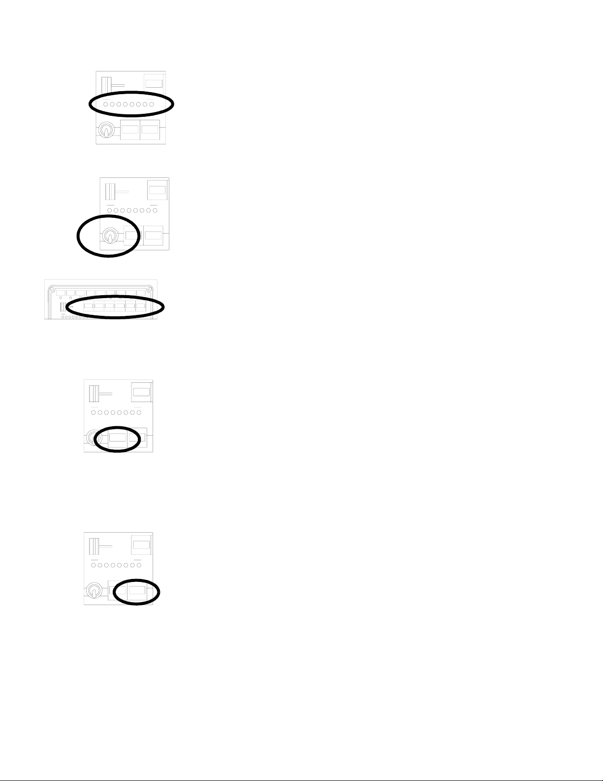
Traffic Advisor Pattern Simulator-
TRAFFICADVISOR
ON
POWER
ON
POWER
TRAFFIC ADVISOR
TRAFFIC
ADVISOR
TRAFFIC ADVISOR
TRAFFIC
ADVISOR
LOW
LOW
POWER
If the vehicle is equipped with a Whelen Traffic Advisor, the Traffic Advisor pattern simulator
displays the currently selected Traffic Advisor flash sequence (e.g.: If the Traffic Advisor is
a flash-to-left pattern, the pattern simulator will sequentially flash from right to left).
Power Switch -
This switch has 2 positions: Down (MPC02 Off) and Up (MPC02 On). When this switch is in
the Off position, the entire network is inoperative and none of the installed serial
LOW
POWER
communication components will function. When the switch is in the ‘On’ position, all of the
components are functional and may be activated at the operator’s discretion.
Push-button Switches -
The push-button switches activate specific, pre-programmed functions of the serial
communications network. These 6 buttons are referred to as controls 4 (furthest button to
the left) through 9 (furthest button to the right). Refer to the Slide Switch section for
information on the first 3 controls. If you are not sure exactly how each control is
configured, the configuration report, included with the MPC02, details the customized
functions for each control.
Traffic Advisor Control
ON
POWER
ON
POWER
TRAFFIC ADVISOR
TRAFFIC
ADVISOR
TRAFFIC ADVISOR
TRAFFIC
ADVISOR
LOW
POWER
LOW
POWER
This button is designated to control Traffic Advisor functions, if the vehicle is equipped with
a Traffic Advisor. There are 4 patterns that are pre-programmed by the factory. Although
specific patterns can be configured at the customer’s request, the basic, non-custom
patterns are described here for example purposes:
Press Control 8 Sequence to Left
Press Control 8 a second time Sequence to Right
Press Control 8 a third time Split Pattern
Press Control 8 a fourth time Flashing Pattern
To terminate Traffic Advisor operation, press and hold the Traffic Advisor button.
Low Power Activation Control
Pressing this button once, initiates low-intensity light operation. When the low-power mode
has been activated, the diagnostic indicator on the MPC02 lights up to inform the operator
that the low-power operation mode is active. Pressing Low Power a second time, returns
the system to normal, full power operation. It is also the Si-Test™ initiation button. Refer to
the Si-Test™ section for information on this feature.
Si-Test™ -
When Si-Test™ is activated, the MPC02 polls each installed serial communication
component and confirms it’s operating status. To initiate a Si-Test™, press and hold Lo
Power for at least 5 seconds. As each component is tested, it’s diagnostic indicator will turn
on if there is no problem detected, or flash if a failure has been detected. If enabled by the
factory or a factory authorized representative, a series of 3, separate alarm tones will be
heard from the MPC02 whenever a failure has been detected.
Page 3
Page 4
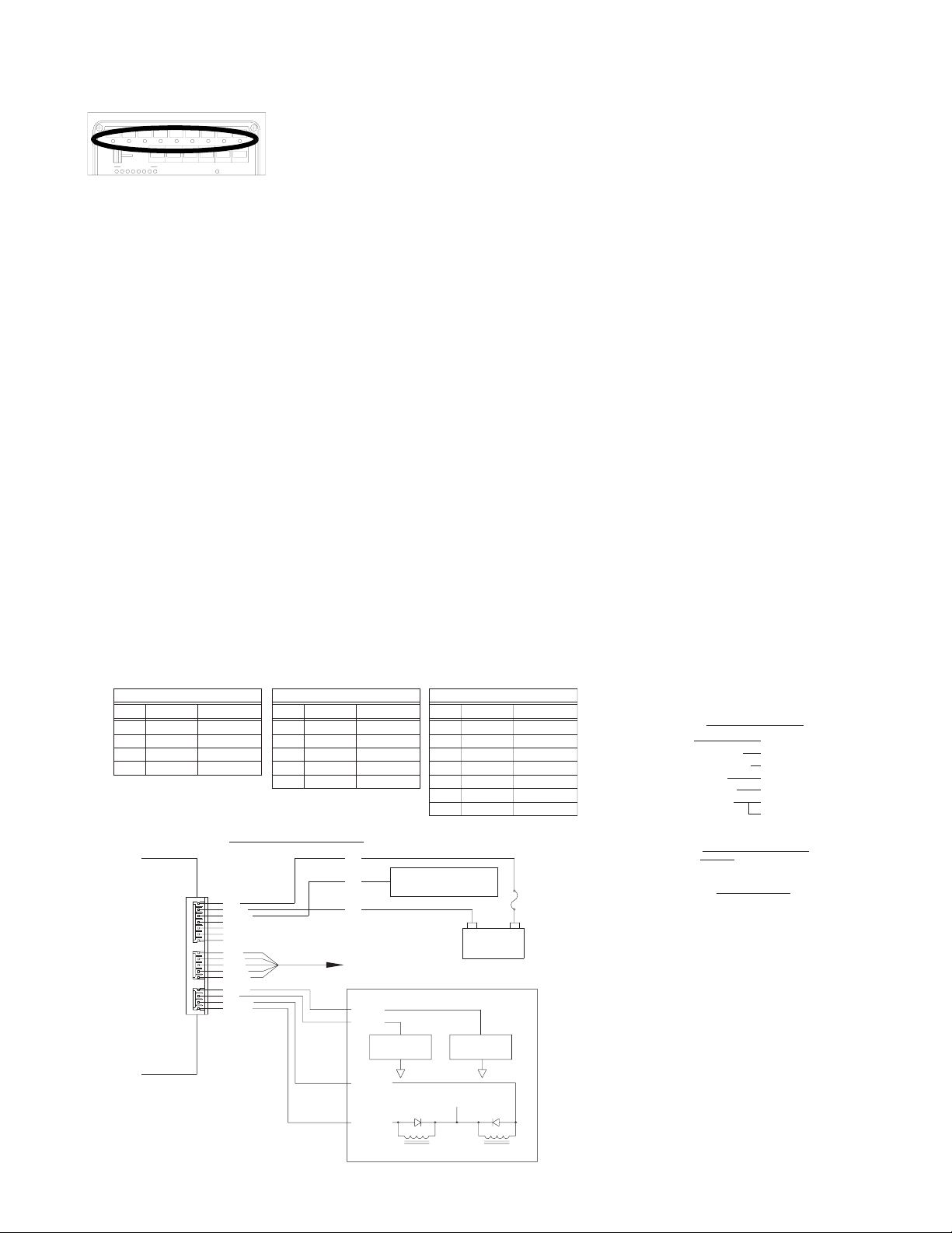
Diagnostic Indicator -
TRAFFICADVISOR
LOW
Window, there is a diagnostic indicator that is programmed to monitor the operation of that
window’s control. When a diagnostic indicator lamp is on, all of the programmed functions
for that control are functioning properly. If a diagnostic indicator is flashing, one or more of
the components being monitored are not functioning. If enabled by the factory or a factory
authorized representative, a series of 3, separate alarm tones will be heard from the
MPC02 whenever a failure has been detected.
Section 2: Additional Features
The MPC02 has been designed to incorporate auxiliary input and output features into the
serial communications network. Essentially, this enables the MPC02 to not only control
non-network components, but to allow non-network components to activate specific
network functions.
Auxiliary Input-
The MPC02 may be connected to 2, non-network components. This allows auxiliary
switches, such as the vehicle’s neutral safety switch, a K-9 thermostat or a burglar alarm, to
activate a pre-programmed, network component. For example: When the interior
temperature of the vehicle has exceeded the K-9 thermostat’s pre-set level, the MPC02 will
automatically activate a specific, K-9 alarm that will alert the operator to the situation. Refer
to the diagram below for wiring details.
Auxiliary Output-
There are 9 diagnostic indicators; one for each of the 9 controls. Below each Label
PIN #
1
2
3
4
POWER
COMM
CTRL
MPC02
J6-AUX. INPUT
COLOR
BROWN
RED
ORANGE
YELLOW
1
J8
1
J7
1
AUX
J6
The MPC02 may be connected to 2, non-network components. This allows the MPC02 to
control auxiliary relays, such as a gunlock. For example: Pushing control button 5 releases
the vehicle’s gunlock. Refer to the diagram below for wiring details.
J7-COMMUNICATION INPUT
FUNCTION
AUX IN 1
AUX IN 2
AUX OUT 1
AUX OUT 2
PIN #
1
2
3
4
5 DRAIN SHIELD
WIRING DIAGRAM
RED
BLACK
YELLOW
BLUE
GREY
WHITE
BLACK
SHIELD
BROWN
RED
ORANGE
YELLOW
CABLE
COLOR
BLUE
WHITE
BLACK
FUNCTION
+RS485
-RS485GREY
NOT USED
NOT USED
#22
#22
#22
To a +12VDC source that is
activated with the vehicle’s
ignition switch
TO
B*LINK NETWORK
AUXIN 1
AUXIN 2
THERMOSTAT
AUXOUT 1
AUXOUT 2
J8- POWER INPUT
PIN #
1
2
3
4
5
6
7
SENSOR
+12VDC
COLOR
RED
BLACK
BACK LIGHTYELLOW
N/C N/C
N/C N/C
N/C N/C
N/C N/C
-
+
12 VDC
BATTERY
OPTIONAL
ALARM
FUNCTION
+V IN
GROUND
5 AMP FUSE
(CUSTOMER SUPPLIED)
SPECIFICATIONS
VIN
I IN (STANDBY)
I IN (BACKLIGHT)
I IN (HORN)
V (HORNRING)
I (HORNRING)
13.2VDC 20%
< 10mA
< 100mA
5 AMPS (MAX)
V IN OR GROUND
10mA (MIN)
5 AMPS (MAX)
COMMUNICATIONS
RS485
9600 BPS
AUX. INPUT
AUX IN 1 (ENABLE)-<1VDC
AUX IN 2 (ENABLE)-<1VDC
AUX OUT 1 (ACTIVE) - < 1 VDC
AUX OUT 2 (ACTIVE) - < 1 VDC
RELAY RELAY
Page 4
 Loading...