

Page 1

®
ENGINEERING COMPANY INC.
51 Winthrop Road
Chester, Connecticut 06412-0684
Phone: (860) 526-9504
Installation Guide:
Mirror-Beam™
2007 Chevy Tahoe
Fax: (860) 526-4078
Internet: www.whelen.com
Sales e-mail: autosale@whelen.com
Canadian Sales e-mail: autocan@whelen.com
Customer Service e-mail: custserv@whelen.com
Safety First
This document provides all the necessary information to allow your Whelen product to be properly and safely installed.
Before beginning the installation and/or operation of your new product, the installation technician and operator must
read this manual completely. Important information is contained herein that could prevent serious injury or damage.
• Proper installation of this product requires the installer to have a good understanding of automotive electronics,
systems and procedures.
• If mounting this product requires drilling holes, the installer MUST be sure that no vehicle components or other
vital parts could be damaged by the drilling process. Check both sides of the mounting surface before drilling
begins. Also de-burr any holes and remove any metal shards or remnants. Install grommets into all wire
passage holes.
• If this manual states that this product may be mounted with suction cups, magnets, tape or Velcro®, clean the
mounting surface with a 50/50 mix of isopropyl alcohol and water and dry thoroughly.
• Do not install this product or route any wires in the deployment area of your air bag. Equipment mounted or
located in the air bag deployment area will damage or reduce the effectiveness of the air bag, or become a
projectile that could cause serious personal injury or death. Refer to your vehicle owner’s manual for the air bag
deployment area. The User/Installer assumes full responsibility to determine proper mounting location, based
on providing ultimate safety to all passengers inside the vehicle.
• For this product to operate at optimum efficiency, a good electrical connection to chassis ground must be
made. The recommended procedure requires the product ground wire to be connected directly to the NEGATIVE
(-) battery post.
• If this product uses a remote device to activate or control this product, make sure that this control is located in
an area that allows both the vehicle and the control to be operated safely in any driving condition.
• Do not attempt to activate or control this device in a hazardous driving situation.
• This product contains either strobe light(s), halogen light(s), high-intensity LEDs or a combination of these
lights. Do not stare directly into these lights. Momentary blindness and/or eye damage could result.
• Use only soap and water to clean the outer lens. Use of other chemicals could result in premature lens cracking
(crazing) and discoloration. Lenses in this condition have significantly reduced effectiveness and should be
replaced immediately. Inspect and operate this product regularly to confirm its proper operation and mounting
condition. Do not use a pressure washer to clean this product.
• It is recommended that these instructions be stored in a safe place and referred to when performing
maintenance and/or reinstallation of this product.
• FAILURE TO FOLLOW THESE SAFETY PRECAUTIONS AND INSTRUCTIONS COULD RESULT IN DAMAGE TO
THE PRODUCT OR VEHICLE AND/OR SERIOUS INJURY TO YOU AND YOUR PASSENGERS!
Automotive: Lightheads
For warranty information regarding this product, visit www.whelen.com/warranty
©2007 Whelen Engineering Company Inc.
Form No. 14097B (050610)
Page 1
Page 2
10mm bolt
under
cover
Remove speaker after
removing
door panel
Remove cover,
remove
two
10mm
bolts
Remove
mirror
inner
cover
Window
lock
Set
screw
behind
cap
Wire
Harness
Boot
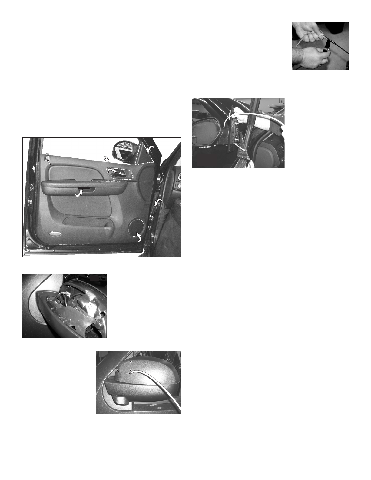
To Remove the Side Mirror Assembly:
1. Remove the cover from behind the door pull and remove the two
10mm bolts underneath (Fig. 1).
2. Locate the small cover behind the door opener, pull it off and remove
the 10mm bolt underneath.
3. There are 16 snap-in fasteners located around the door panel.
Carefully pry the door panel loose but do not remove the panel yet.
4. Behind the door opener assembly remove the two 7mm bolts.
5. Unplug the 3 connectors behind the door pull. IMPORTANT: Be sure
to remember where the connectors plug in for reassembly.
6. Remove the door lock button and pull the door panel off then unplug
the wire harness that goes to the mirror.
7. Remove the triangular cover covering the inside of the mirror base.
Remove the three bolts underneath the cover that hold the mirror
assembly on then remove the mirror assembly from the vehicle.
Window lock
Window lock
Set screw
Set screw
behind cap
behind cap
Remove cover,
Remove cover,
remove two
remove two
10mm bolts
10mm bolts
Two 7mm bolts
behind opener
and door panel
10mm bolt
10mm bolt
under cover
under cover
DOOR PULL
Remove speaker after
Remove speaker after
removing door panel
removing door panel
DOOR OPENER
Remove
Remove
mirror
mirror
inner
inner
cover
cover
Wire
Wire
Harness
Harness
Boot
Boot
Fig. 1
Preparing Mirror Assembly:
Fig. 2
Preparing Wire Harness:
Because the harness cable
must be routed through a
specific, narrow and twisting
path within the mirror
assembly, it may be necessary
to temporarily extend the
length of the harness.
1. Locate the ty-wrap
2. Locate the end of the harness cable that has SOCKET-type terminals
(included) and cut the
fastener-end off.
installed on the free wires. Cut off the non-insulated wire (not used in
this application).
1. Remove the cover from the
front of the mirror assembly
(Fig. 2). (The cover snaps
off. Be careful not to brake
the snaps.)
2. Measure as shown (Fig. 3)
and mark off this location
onto the mirror assembly
cover, than drill the wire
hole through the cover
using a 3/8” drill.
Fig. 3
2¼"
2¼"
3¼"3¼"
3. Strongly secure the ty-wrap to the
harness cable with electrical or similar
Fig. 4
tape. It is important to have a sufficient
length of the ty-wrap secured to the
harness (2” minimum) (Fig. 4).
Routing Harness Cable:
1. Insert the end of the ty-wrap into the
mirror assembly via the same pathway
as the mirror power cable. Push the ty-wrap through this opening
until the end of the ty-wrap sticks out of the mirror base. Pull the tywrap until slack in the harness is gone (Fig. 5).
2. Pull the wire through
the housing and out
the wire exit hole.
There should not be
more than 4 - 5” of
harness sticking out of
the mirror assembly.
3. Insert the end of the
harness into the 3/8”
hole you drilled in the
Fig. 5
mirror assembly cover
and snap the cover
back onto the mirror assembly.
4. Remove the ty-wrap from the harness and insert the wire terminals
into their 2 - 3 position connectors (see wiring diagrams).
Affixing Mirror-Beam™ Housing to Mirror Assembly:
Note:The following procedure requires that the mirror assembly be
no colder than 60°F (18°C).
1. Remount the mirror assembly onto the mounting bracket using the
original hardware. Make sure that neither of the harness cables are
crimped or pinched. Tighten the bolts firmly.
2. Thoroughly clean the plastic mirror assembly and the inside surface
of the Mirror-Beam housing using a 50/50 mixture of isopropyl (not
rubbing) alcohol and water. Dry completely.
3. Locate the three, 6” strips of double-sided adhesive tape (included)
and position one 6” strip on the top and one on the bottom of the
mirror assembly. When properly positioned, the tape will be centered
between the inboard and outboard ends of the mirror assembly and
the leading edge of the tape will be set back approximately 1/4” from
the rear (mirror side) edge of the assembly. After the tape is
positioned, it is important to apply pressure to the protective backing
so that the tape adheres to the surface.
4. Cut the remaining 6” length of tape in half. Using the procedure
outlined in the previous step, adhere one 3” length of tape to the
outboard end of the mirror assembly and the remaining 3” length to
the curved “neck” of the mirror assembly.
5. Fold the protective backing strips on the top, bottom and outboard
tape strips so that 1/2” to 3/4” of backing is extended over the rear
edge of the plastic mirror assembly. Trim and remove the exposed
tape. Remove the protective backing from the tape strip on the “neck”
of the mirror.
6. Mount the Mirror-Beam housing onto the mirror assembly as shown.
The housing must fully engage the mirror assembly.
Press the housing firmly onto the exposed tape on the “neck” of the
mirror.
7. The remaining protective backing strips must now be removed. The
housing must not be in contact with the backing strips. Starting with
the outboard strip, and using a small, flat blade screwdriver gently
pry the housing about 1/4” away from the mirror assembly. Carefully
pull the protective strip “tab” created in step 6, and gently remove it
completely from the tape strip. Do not allow the strip to tear while
being removed.
Page 2
Page 3

8. Repeat for the tape strips on the top and bottom of the assembly.
9. Apply pressure to the Mirror-Beam™ assembly at the tape locations.
Maintain pressure for a minimum of 20 minutes to allow the tape to
properly setup. This can be accomplished by wrapping the MirrorBeam/mirror assembly tightly with adhesive tape.
WARNING! The tape adhesive used in this procedure is fully bonded
after 72 hours @ 70°F (21°C). During this period, do not
expose the Mirror-Beam to any unnecessary force, such
as the high-pressure water from a car wash.
WARNING! The outer surfaces of this product may be cleaned with
mild soap and water. Use of any other chemicals may
void product warranty. Do not use a pressure washer.
10. Locate the factory-drilled hole in the Mirror-Beam housing. Using a
.125” drill bit and the Mirror-Beam™ housing as a template, drill a
hole into the mirror housing. Locate the #8 x 1/2” sheet metal screw
(included) and secure the Mirror-Beam housing to the mirror housing.
Re-assembling the Mirror-Beam™ Assembly:
1. Re-connect the mirror assembly to it’s main power harness. Route
the Mirror-Beam™ harness through the door, along the same path as
the vehicle’s main power harness and connect to power (see wiring
diagrams). Remove the door speaker for easy access.
2. Cut the non-insulated wire off the harness. After the connections are
complete, confirm proper operation.
3. Using the original hardware, remount the mirror onto the vehicle.
WARNING! All customer supplied wires that connect to the
positive terminal of the battery must be sized to
supply at least 125% of the maximum operating
current and FUSED
at the battery to carry that load.
DO NOT USE CIRCUIT BREAKERS WITH THIS
PRODUCT!
IMPORTANT! It is the responsibility of the installation technician to
make sure that the installation and operation of this
product will not interfere with or compromise the
operation or efficiency of any vehicle equipment!
IMPORTANT! Before returning the vehicle to active service, visually
confirm the proper operation of this product, as well
as all vehicle components/equipment.
WARNING! The strobe light power supply is a high voltage device.
Do not remove strobe tubes or dismantle strobe light
head assemblies in the system while it is in operation.
Wait 10 minutes after turning off power before starting
work or any trouble shooting.
IMPORTANT WARNING!
CAUTION! DO NOT LOOK DIRECTLY AT THESE LEDS WHILE THEY ARE ON.
MOMENTARY BLINDNESS AND/OR EYE DAMAGE COULD RESULT!
Items 8 thru 12 (LED FLASHER)
WHITE-VIOLET
This wire will be
the color of the LED
BLACK
Scan-Lock™
3A Fuse
Items 3 thru 7 (STROBE)
RED
BLACK
WHITE
+12 VDC
GROUND
ANODE
CATHODE
TRIGGER
Items 22 thru 29 (LINEAR-LED)
WHITE-VIOLET
GREY
This wire will be
the color of the LED
BLACK
30
31
21
89
10
11 1 2
15
5
3
4
7
6
2
20
1
25
25
222324
28
29
26
27
24
OPERATION: Depending on which lighthead is installed in your
Mirror-Beam, you may be able to change flash patterns or
synchronize lightheads to flash simultaneously or alternately.
This manual gives you basic wiring and installation.
For information on the operation of your Mirror-Beam refer to
the lighthead manual included.
3A Fuse
14
Scan-Lock™
SYNC
+12VDC
GROUND
16
13
QTY QTY QTY
21212
A/R
A/R
A/R
A/R
A/R
111
111
1
1
11
2
11
111
PART NUMBER:
01-068360 8A__
01-068360 9A__
NOTE: If your Mirror-Beam™ housing does not have a metal insert where the
lighthead mounts to the housing, ITEMs 20 and 21 secure the lighthead.
A/R
A/R
A/R
A/R
A/R
A/R
A/R
A/R
ITEM
PART NUMBER
01-068360_A_L
01-068360_A_P
01-068360_A_S
14-104216-120
1
11-763226-000
2
1
01-0683565-A0
3
01-0683565-B0
4
5
01-0683565-C0
6
01-0683565-G0
01-0683565-R0
7
02-0383558513
8
A/R
02-0383558523
9
A/R
10
A/R
02-03835585C3
02-0383558543
A/R
11
02-0383558553
A/R
12
10-0320776-00
13
1
14
10-0522839-**
15-08121B-082
15
1
1
3
16
17
18
19
1
20
2
2
21
22
23
24
25
26
27
28
29
30
1
31
66-0416642-00
46-0742172-15
01-0415532-00
26-0315001-14
15-081416-100
21-12080905-1
01-066C289110
01-066C289120
01-066C289130
01-066C289140
01-066C289150
01-066C290-D0
01-066C290-E0
01-066C290-J0
11-484750-R01
11-484750-L01
Driver side
Passenger side
LIGHTHEAD
COLOR
MODEL
33
22
2
OR
MIRROR BEAM / LED - '07 TAHOE
MIRROR BEAM / PASSIVE LINEAR - '07 TAHOE
MIRROR BEAM / STROBE - '07 TAHOE
SCREW, #10-24 X 3/4" PPHMS
FLANGE, BLACK
ASSY, LINEAR STROBE - AMBER/AMP
ASSY, LINEAR STROBE - BLUE/AMP
ASSY, LINEAR STROBE - CLEAR/AMP
ASSY, LINEAR STROBE - GREEN/AMP
ASSY, LINEAR STROBE - RED/AMP
ASSY, LED FLASHER - AMBER/CLEAR 3 POS
ASSY, LED FLASHER - BLUE/CLEAR 3 POS
ASSY, LED FLASHER - WHITE/CLEAR 3 POS
ASSY, LED FLASHER - GREEN/CLEAR 3 POS
ASSY, LED FLASHER - RED/CLEAR 3 POS
LABEL, MADE IN USA FLAG
LABEL, P/N MIRROR BEAM (PASSENGER)
SCREW, #8 X 1/2" PPHSMS TYPE A SS BLACK
TAPE, MOUNTING
CABLE ASSEMBLY, 3/C
KIT, CABLE INSTALLATION 3/C
TY-WRAP, 14 1/2" BLACK / not shown
SCREW, 8 X 5/8 PPHSMS SS
SCREW GROMMET, #8
ASSY, LINEAR LED - AMBER/CLEAR/AMP
ASSY, LINEAR LED - BLUE/CLEAR/AMP
ASSY, LINEAR LED - WHITE/CLEAR/AMP
ASSY, LINEAR LED - GREEN/CLEAR/AMP
ASSY, LINEAR LED - RED/CLEAR/AMP
ASSY, LINEAR LED - RED-WHT/CLEAR/AMP
ASSY, LINEAR LED - BLU-WHT/CLEAR/AMP
ASSY, LINEAR LED - RED-BLU/CLEAR/AMP
HOUSING, PASS. SIDE - '07 TAHOE
HOUSING, DRIVER SIDE - '07 TAHOE
MODEL
COLOR
TAHOEA=
A=
AMBER-AMBER
B=
BLUE-BLUE
C=
CLEAR-WHITE
G=
GREEN-GREEN
R=
RED-RED
1=
AMBER-CLEAR
DESCRIPTION
BLUE-CLEAR
2=
GREEN-CLEAR
4=
RED-CLEAR
5=
RED/WHT-CLEAR
D=
BLU/WHT-CLEAR
E=
RED/BLU - CLEAR
J=
LIGHTHEAD
S=
L=
P=
If your has a metal insert, ITEM 1 secures the lighthead.Mirror-Beam™
STROBE
LED (5mm)
LINEAR LED
Page 3
 Loading...