

Page 1

®
ENGINEERING COMPANY INC.
51 Winthrop Road
Chester, Connecticut 06412-0684
Phone: (860) 526-9504
Fax: (860) 526-4078
Internet: www.whelen.com
Sales e-mail: autosale@whelen.com
Canadian Sales e-mail: canadiansales@whelen.com
Customer Service e-mail: custserv@whelen.com
Installation Guide:
Mirror-Beam™ ION™ Series™ and
ION™ V-Series™
Super-LED® Lighthead
2011 Dodge Charger
Whelen’s emergency vehicle warning devices must be properly mounted and wired in order to be effective and safe. Read and follow all of Whelen’s
written instructions when installing or using this device. Emergency vehicles are often operated under high speed stressful conditions which must be
accounted for when installing all emergency warning devices. Controls should be placed within convenient reach of the operator so that he can operate
the system without taking his eyes off the roadway. Emergency warning devices can require high electrical voltages and/or currents. Properly protect and
use caution around live electrical connections.Grounding or shorting of electrical connections can cause high current arcing, which can cause personal
injury and/or vehicle damage, including fire. Many electronic devices used in emergency vehicles can create or be affected by electromagnetic
interference. Therefore, after installation of any electronic device it is necessary to test all electronic equipment simultaneously to insure that they operate
free of interference from other components within the vehicle. Never power emergency warning equipment from the same circuit or share the same
grounding circuit with radio communication equipment. All devices should be mounted in accordance with the manufacturer’s instructions and securely
fastened to vehicle elements of sufficient strength to withstand the forces applied to the device. Driver and/or passenger air bags (SRS) will affect the way
equipment should be mounted. This device should be mounted by permanent installation and within the zones specified by the vehicle manufacturer, if
any. Any device mounted in the deployment area of an air bag will damage or reduce the effectiveness of the air bag and may damage or dislodge the
device. Installer must be sure that this device, its mounting hardware and electrical supply wiring does not interfere with the air bag or the SRS wiring or
sensors. Mounting the unit inside the vehicle by a method other than permanent installation is not recommended as unit may become dislodged during
swerving; sudden braking or collision. Failure to follow instructions can result in personal injury. Whelen assumes no liability for any loss resulting from the
use of this warning device. PROPER INSTALLATION COMBINED WITH OPERATOR TRAINING IN THE PROPER USE OF EMERGENCY WARNING
DEVICES IS ESSENTIAL TO INSURE THE SAFETY OF EMERGENCY PERSONNEL AND THE PUBLIC.
Warnings to Users
Warnings to Installers
Whelen’s emergency vehicle warning devices are intended to alert other operators and pedestrians to the presence and operation of emergency vehicles
and personnel. However, the use of this or any other Whelen emergency warning device does not guarantee that you will have the right-of-way or that
other drivers and pedestrians will properly heed an emergency warning signal. Never assume you have the right-of-way. It is your responsibility to proceed
safely before entering an intersection, driving against traffic, responding at a high rate of speed, or walking on or around traffic lanes. Emergency vehicle
warning devices should be tested on a daily basis to ensure that they operate properly. When in actual use, the operator must ensure that both visual and
audible warnings are not blocked by vehicle components (i.e.: open trunks or compartment doors), people, vehicles, or other obstructions. It is the user’s
responsibility to understand and obey all laws regarding emergency warning devices. The user should be familiar with all applicable laws and regulations
prior to the use of any emergency vehicle warning device. Whelen’s audible warning devices are designed to project sound in a forward direction away
from the vehicle occupants. However, because sustained periodic exposure to loud sounds can cause hearing loss, all audible warning devices should be
installed and operated in accordance with the standards established by the National Fire Protection Association.
Safety First
This document provides all the necessary information to allow your Whelen product to be properly and safely installed. Before beginning the installation
and/or operation of your new product, the installation technician and operator must read this manual completely. Important information is contained herein
that could prevent serious injury or damage.
• Proper installation of this product requires the installer to have a good understanding of automotive electronics, systems and procedures.
• Whelen Engineering recommends the use of waterproof butt splices and/or connectors if that connector could be exposed to moisture.
• Failure to use specified installation parts and/or hardware will void the product warranty.
• If mounting this product requires drilling holes, the installer MUST be sure that no vehicle components or other vital parts could be damaged
by the drilling process. Check both sides of the mounting surface before drilling begins. Also de-burr the holes and remove any metal shards
or remnants. Install grommets into all wire passage holes.
• If this manual states that this product may be mounted with suction cups, magnets, tape or Velcro®, clean the mounting surface with a 50/50
mix of isopropyl alcohol and water and dry thoroughly.
• Do not install this product or route any wires in the deployment area of your air bag. Equipment mounted or located in the air bag deployment
area will damage or reduce the effectiveness of the air bag, or become a projectile that could cause serious personal injury or death. Refer to
your vehicle owner’s manual for the air bag deployment area. The User/Installer assumes full responsibility to determine proper mounting
location, based on providing ultimate safety to all passengers inside the vehicle.
• For this product to operate at optimum efficiency, a good electrical connection to chassis ground must be made. The recommended
procedure requires the product ground wire to be connected directly to the NEGATIVE (-) battery post (this does not include products that use
cigar power cords).
• If this product uses a remote device for activation or control, make sure that this device is located in an area that allows both the vehicle and
the device to be operated safely in any driving condition.
• Do not attempt to activate or control this device in a hazardous driving situation.
• This product contains either strobe light(s), halogen light(s), high-intensity LEDs or a combination of these lights. Do not stare directly into
these lights. Momentary blindness and/or eye damage could result.
• Use only soap and water to clean the outer lens. Use of other chemicals could result in premature lens cracking (crazing) and discoloration.
Lenses in this condition have significantly reduced effectiveness and should be replaced immediately. Inspect and operate this product
regularly to confirm its proper operation and mounting condition. Do not use a pressure washer to clean this product.
• It is recommended that these instructions be stored in a safe place and referred to when performing maintenance and/or reinstallation of this
product.
• FAILURE TO FOLLOW THESE SAFETY PRECAUTIONS AND INSTRUCTIONS COULD RESULT IN DAMAGE TO THE PRODUCT OR VEHICLE
Automotive: Lightheads
AND/OR SERIOUS INJURY TO YOU AND YOUR PASSENGERS!
©2011 Whelen Engineering Company Inc.
Form No.14509B (112613)
For warranty information regarding this product, visit www.whelen.com/warranty
Page 1
Page 2
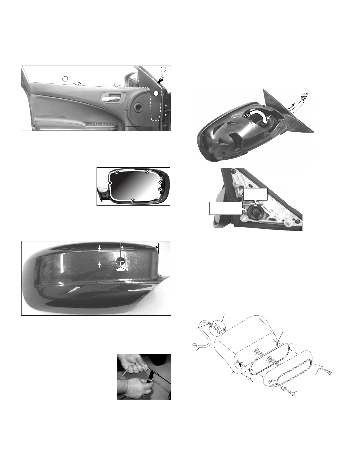
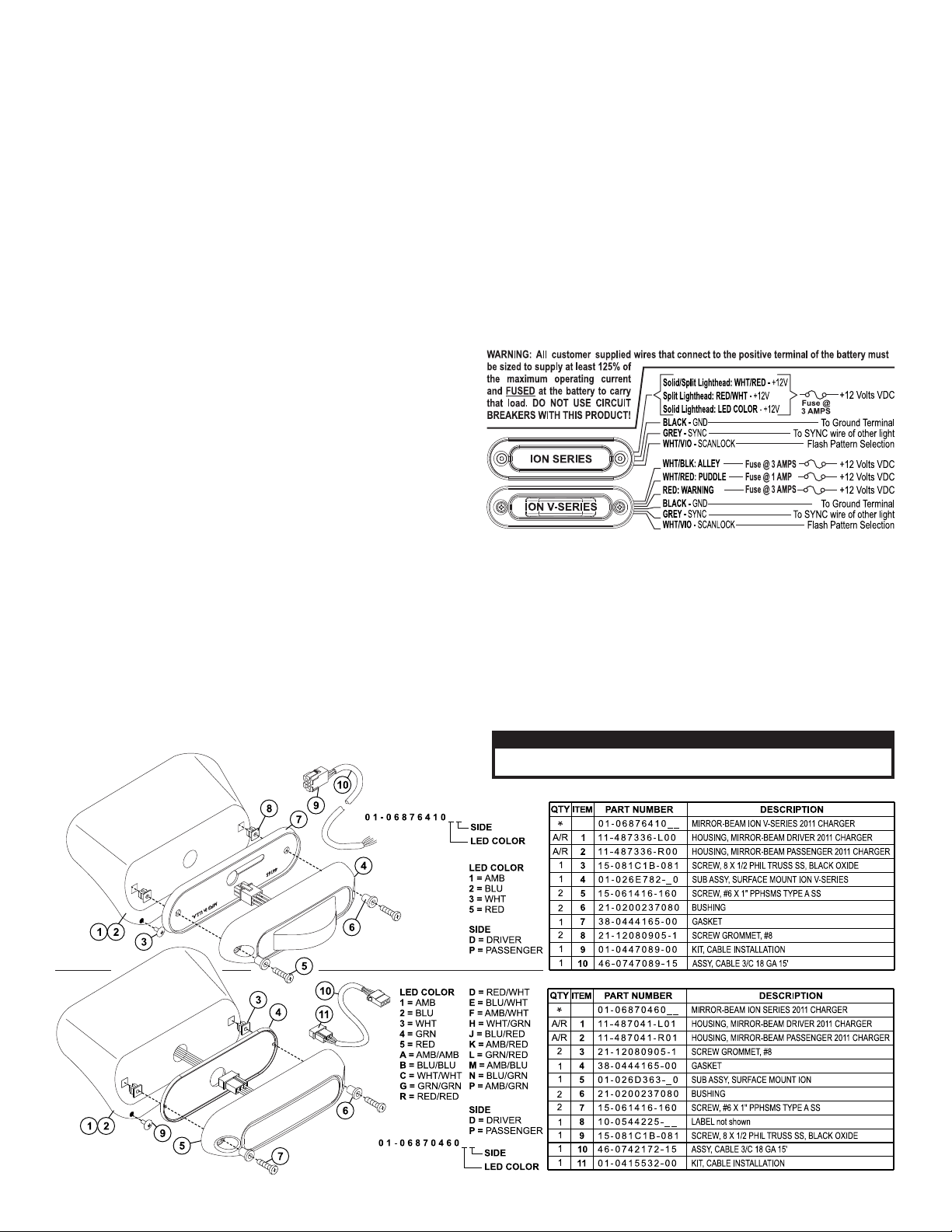
Fig. 5
ION™
LIGHTHEAD
#6 X 1 PPHSMS
#8 X 1/2"
PHILLIPS
TRUSS
SCREW
#8 SCREW
GROMMET
GASKET
BUSHING
Exits mirror
assembly
base
Mirror-Beam™
HOUSING
Position connectors between Mirror-Beam™ housing and mirror housing
Exits front
of mirror
assembly
3.4" HOLE
5/8"
FROM
SEAM
FROM
EDGE
Fig. 2
2-5/8"
APPROXIMATE LOCATION
OF SNAPS
Fig. 4
Bottom of base (Facing road)
Insert
harness
here
Insert
harness
here
Insert
harness
here
Cut section
of grommet
out here
Pull grommet
out to feed the
harness through
Harness
exits here
To Remove the Side Mirror Assembly:
Remove clips from behind door panel
Pull
panel
out
Access
mirror
base
A
B
C
Fig.1
1. Remove the two clips (Fig. 1) from behind the top of the door panel,
which hold the door panel on (A). Carefully pull the door panel out,
just enough so that the panel covering the mirror base can be pulled
away to access the mirror base (B). The panel covering the mirror
base snaps in.
2. Carefully pull the panel covering mirror base away and remove the
three nuts holding the mirror assembly on, unplug the wiring and
remove the mirror assembly from the vehicle.
Preparing Mirror Assembly:
1. Remove the cover from the
front of the mirror assembly.
The cover snaps off. Be
careful not to brake the snaps.
The safest method of
removing the cover is to
carefully insert a small
screwdriver around the edge
of the mirror and disengage the snaps (See above).
2. Measuring from the seam across the top and the inner edge of the
mirror assembly cover, mark off the wire hole location (Fig. 2). Drill
the wire hole through the cover using a 3/4” drill.
Routing Harness Cable:
First, carefully pull the grommet that holds the mirror power cable,
out of the base so that you will be able to feed the Mirror-Beam™
cable through the wire hole. The power cable wires are attached to
the grommet so be careful not to pull the wires out of their
connection to the mirror.
1. Insert the ty-wrap into the front of the mirror assembly via the same
pathway as the mirror power cable. Push the ty-wrap through this
opening until the end of the ty-wrap comes out of the mirror base.
Pull the ty-wrap until slack in the harness is gone (Fig. 4).
Preparing the Wire Harness:
Because the harness cable must be routed through a specific,
narrow and twisting path within the mirror assembly, it may be
necessary to temporarily extend the length of the harness.
1. Locate the ty-wrap (included) and cut
the fastener-end off.
2. Locate the end of the harness cable
that has PIN-type terminals installed on
the free wires. Cut off the non-insulated
wire (not used in this application).
3. Strongly secure the ty-wrap to the
harness cable with electrical or similar
tape. It is important to have a sufficient
length of the ty-wrap secured to the harness (2” minimum) (Fig. 3).
2. Pull the harness through the mirror assembly and out the wire exit
hole in the base. There should not be more than 4 - 5” of harness
protruding from the front of the mirror assembly.
3. Snap the grommet with the mirror power cable back into its hole. You
will have to cut out a small amount of the outside of the grommet to
accommodate the Mirror-Beam™ cable (Fig. 4). Apply a small
amount of RTV sealant around the cable where you cut the grommet.
4. Insert the end of the harness into the 3/4” hole you drilled in the
mirror assembly cover and snap the cover back onto the mirror
assembly.
Fig. 3
5. Remove the ty-wrap from the harness. Install the socket connector
(supplied) onto the end of the cable coming out of the front of the
mirror assembly (Fig. 5). (see wiring diagram).
Page 2
Page 3
Affixing Mirror-Beam™ Housing to Mirror Assembly:
CAUTION! DO NOT LOOK DIRECTLY AT THESE LED’S WHILE THEY ARE ON.
MOMENTARY BLINDNESS AND/OR EYE DAMAGE COULD RESULT!
IMPORTANT WARNING!
1. Reconnect the mirror power cable and remount the mirror assembly
onto the vehicle using the original hardware. Route the MirrorBeam™ harness through the door, along the same path as the
vehicle’s main power harness. Make sure that neither of the harness
cables are crimped or pinched. Tighten the nuts firmly and reattach
the door panel and the panel covering the mirror assembly base.
2. Mount the lighthead to the Mirror-Beam™ housing and plug the
lighthead into the cable. Tuck this connection between the MirrorBeam™ housing and the mirror assembly (Fig. 5).
3. NOTE: The following procedure requires that the mirror
assembly be no colder than 60°F (18°C). Thoroughly clean the
plastic mirror assembly and the inside surface of the Mirror-Beam™
housing using a 50/50 mixture of isopropyl (not rubbing) alcohol and
water. Dry completely.
4. Locate the three, 6” strips of double-sided adhesive tape (included)
and position one 6” strip on the top and one on the bottom of the
mirror assembly. When properly positioned, the tape will be centered
between the inboard and outboard ends of the mirror assembly and
the leading edge of the tape will be set back approximately 1/4” from
the rear (mirror side) edge of the assembly. After the tape is
positioned, it is important to apply pressure to the protective backing
so that the tape adheres to the surface.
5. Cut the remaining 6” length of tape in half. Using the procedure
outlined in the previous step, adhere one 3” length of tape to the
outboard end of the mirror assembly and the remaining 3” length to
the curved “neck” of the mirror assembly.
6. Fold the protective backing strips on the top, bottom and outboard
tape strips so that 1/2” to 3/4” of backing is extended over the rear
edge of the mirror assembly. Trim and remove the exposed tape.
Remove protective backing from tape strip on “neck” of mirror.
7. Mount the Mirror-Beam™ housing onto the mirror assembly. The
housing must fully engage the mirror assembly. Press the
housing firmly onto the exposed tape on the “neck” of the mirror.
8. Remove the remaining protective backing strips. The housing must
not be in contact with the backing strips. Starting with the outboard
strip, using a small, flat blade screwdriver gently pry the housing
about 1/4” away from the mirror assembly. Carefully pull the
protective strip “tab” created in step 6, and remove it completely from
the tape strip. Do not allow the strip to tear while being removed.
Repeat for the tape strips on the top and bottom of the assembly.
9. Apply pressure to the Mirror-Beam™ housing at the tape locations.
Maintain pressure for a minimum of 20 minutes to allow the tape to
properly setup. This can be accomplished by wrapping the MirrorBeam™/mirror assembly tightly with adhesive tape.
WARNING: The tape adhesive used in this procedure is fully bonded
after 72 hours @ 70°F (21°C). During this period, do not expose the
Mirror-Beam™ to any unnecessary force, such as the high-pressure
water from a car wash.
WARNING: The outer surfaces of this product may be cleaned with
mild soap and water. Use of any other chemicals may void product
warranty. Do not use a pressure washer.
10. Using the factory-drilled hole in the Mirror-Beam™ housing as a
guide, drill a hole into the mirror housing (1/8” drill bit). Secure the
Mirror-Beam™ housing to the mirror housing with the supplied
#8 X 1/2” black phillips truss screw.
Connecting the Mirror-Beam™ to Power:
1. Re-connect the mirror assembly to it’s main power harness. Route
the Mirror-Beam™ harness through the door, along the same path as
the vehicle’s main power harness and connect to power.
2. Cut the non-insulated wire off the harness. After the connections are
complete, confirm proper operation.
IMPORTANT: It is the responsibility of the installation technician to
make sure that the installation and operation of this product will not
interfere with or compromise the operation or efficiency of any
vehicle equipment! Before returning the vehicle to active service,
visually confirm the proper operation of this product, as well as all
vehicle components/equipment.
Page 3
 Loading...