

Page 1

®
ENGINEERING COMPANY INC.
51 Winthrop Road
Chester, Connecticut 06412-0684
Phone: (860) 526-9504
Mirror-Beam™ Model MBCV98
1998 Ford Crown Victoria
Installation Guide:
Fax: (860) 526-4078
Internet: www.whelen.com
Sales e-mail: autosale@whelen.com
Canadian Sales e-mail: canadiansales@whelen.com
Customer Service e-mail: custserv@whelen.com
Safety First
This document provides all the necessary information to allow your Whelen product to be properly and safely installed.
Before beginning the installation and/or operation of your new product, the installation technician and operator must
read this manual completely. Important information is contained herein that could prevent serious injury or damage.
• Proper installation of this product requires the installer to have a good understanding of automotive electronics,
systems and procedures.
• If mounting this product requires drilling holes, the installer MUST be sure that no vehicle components or other
vital parts could be damaged by the drilling process. Check both sides of the mounting surface before drilling
begins. Also de-burr any holes and remove any metal shards or remnants. Install grommets into all wire
passage holes.
• If this manual states that this product may be mounted with suction cups, magnets, tape or Velcro™, clean the
mounting surface with a 50/50 mix of isopropyl alcohol and water and dry thoroughly.
• Do not install this product or route any wires in the deployment area of your air bag. Equipment mounted or
located in the air bag deployment area will damage or reduce the effectiveness of the air bag, or become a
projectile that could cause serious personal injury or death. Refer to your vehicle owners manual for the air bag
deployment area. The User/Installer assumes full responsibility to determine proper mounting location, based
on providing ultimate safety to all passengers inside the vehicle.
• For this product to operate at optimum efficiency, a good electrical connection to chassis ground must be
made. The recommended procedure requires the product ground wire to be connected directly to the NEGATIVE
(-) battery post.
• If this product uses a remote device to activate or control this product, make sure that this control is located in
an area that allows both the vehicle and the control to be operated safely in any driving condition.
• Do not attempt to activate or control this device in a hazardous driving situation.
• This product contains either strobe light(s), halogen light(s), high-intensity LEDs or a combination of these
lights. Do not stare directly into these lights. Momentary blindness and/or eye damage could result.
• Use only soap and water to clean the outer lens. Use of other chemicals could result in premature lens cracking
(crazing) and discoloration. Lenses in this condition have significantly reduced effectiveness and should be
replaced immediately. Inspect and operate this product regularly to confirm its proper operation and mounting
condition. Do not use a pressure washer to clean this product.
• It is recommended that these instructions be stored in a safe place and referred to when performing
maintenance and/or reinstallation of this product.
• FAILURE TO FOLLOW THESE SAFETY PRECAUTIONS AND INSTRUCTIONS COULD RESULT IN DAMAGE TO
THE PRODUCT OR VEHICLE AND/OR SERIOUS INJURY TO YOU AND YOUR PASSENGERS!
Automotive: Lightheads
For warranty information regarding this product, visit www.whelen.com/warranty
©1998 Whelen Engineering Company Inc.
Form No.13301H (092210)
Page 1
Page 2
To Remove the Side Mirror Assembly:
1. Remove the driver side door panel from the vehicle.
2. Remove the three hex nuts that secure the mirror assembly to the vehicle. Unplug the mirror assembly harness cable from the door’s power
harness and carefully remove the mirror assembly from the vehicle.
The glamour cap will now be removed from the mirror assembly.
Fig. 1
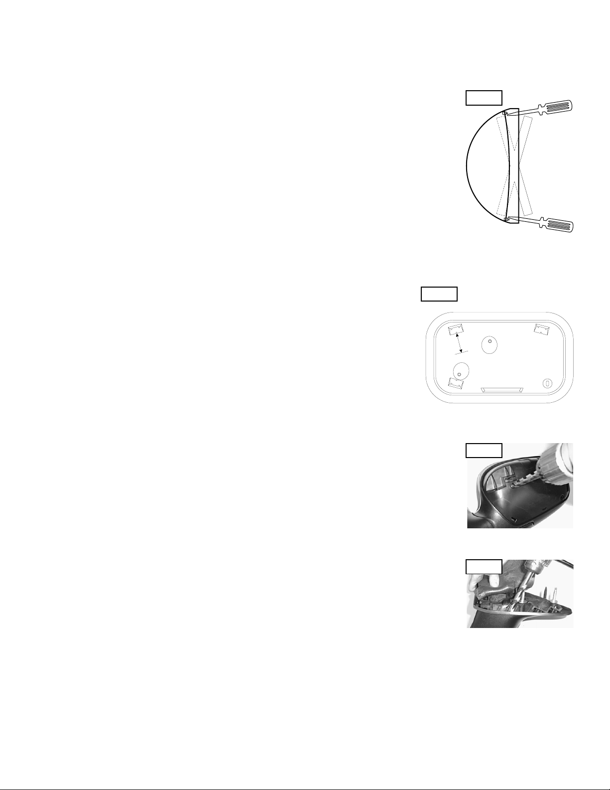
To Remove the Glamour Cap from the Mirror Assembly:
1. To remove the glamour cap from the mirror assembly, the glamour caps three retaining tabs must be carefully
lifted off the rear housing retaining pins. This is accomplished with a small flatblade screwdriver or other
suitable device.
2. To gain access to the glamour caps upper retaining tabs, the mirror must be gently positioned so that it’s lower
edge is pressed inwards as far as it will travel. This will allow the two, upper retaining tabs to be accessed with
Side View
the screwdriver.
3. Position the screwdriver blade under either of the upper retaining tabs and pry tab upwards and off its retaining
pin. Repeat for remaining upper retaining tab.
4. To gain access to the glamour cap’s lower retaining tab, the mirror must be gently positioned so that it’s upper
edge is pressed inwards as far as it will travel. This will allow the lower retaining tab to be accessed with the
screwdriver.
5. Position the screwdriver blade over the retaining tab and pry tab downwards and off its retaining pin. With all three retaining tabs free, pull
glamour cap and its guide pin away from the mirror assembly.
The mirror assembly will now be prepared for the new strobe harness cable.
To Prepare the Mirror Assembly:
1. With the glamour cover removed, look at the rear of the mirror assembly. Locate the upper
retaining tab slot indicated. Draw a perpendicular line that extends 1 inch from the middle of the
Fig. 2
(Rear view with Glamour Cap removed)
Left (Driver) Side Mirror
bottom of the slot.
2. At the end of this perpendicular line, carefully drill a 1” hole into the mirror assembly.
1“ Inch
3. Now fold the lower section of the triangular foam mounting gasket so that access to the lower
section of the mirror assembly’s mounting surface is gained.
4. Locate the area along the bottom of the mirror assembly’s mounting surface where the mirror
harness has been routed from inside the assembly. The adjacent passage (closer to the rear of the
assembly) will also be drilled using a 3/8” drill bit. As shown in Fig. 4, make sure that as the hole is
drilled, the bit stays parallel with walls of the passage.
NOTE: The location of these holes are critical. Be sure that the indicated distances are measured accurately. Failure to do so could result
in damage to the mirror’s motor and/or wiring components.
To Prepare the Strobe Harness:
NOTE: Because the strobe harness must be routed through a specific, narrow and twisting path within the
mirror assembly, it is necessary to temporarily extend the length of the harness with a make-shift “snake”.
1. Locate the tie-wrap included with your Mirror-Beam™ and cut the fastener-end off.
2. Locate the end of the strobe harness that has SOCKET-type terminals installed on the free wires. If present, cut
off the non-insulated wire (it is not used in this application).
3. Strongly secure the tie-wrap to the strobe harness with electrical or similar tape. It is important to have a
sufficient length of the tie-wrap secured to the harness jacket (at least 2”).
The strobe harness will now be routed through the mirror assembly.
Fig. 3
Routing the Strobe Harness:
1. Insert the end of the tie-wrap through the 3/8” hole drilled in step 4 of the “To prepare the mirror assembly...”
section.
2. Feed the tie-wrap through the mirror assembly until the tie-wrap can be pulled through the 1” hole drilled in step
2 of the “To prepare the mirror assembly...” section. There should not be more than 4 or 5 inches of harness
sticking out of the hole. If the length is different from this, adjust harness length accordingly.
The tie-wrap is now removed from the harness and the wire terminals inserted into their 3 position connector
(supplied) as follows (For detailed information, refer to the instruction tag attached to the harness):
Position 1 = Red Position 2 = Black Position 3 = White (Clear)
Fig. 4
Page 2
Page 3

Affixing the Mirror-Beam™ Housing to the Mirror Assembly:
NOTE: The following procedure requires that the mirror assembly be no colder than 60°F (18°C).
1. Thoroughly clean the plastic mirror assembly and the inside surface of the housing using a 50/50 mixture of
isopropyl (not rubbing) alcohol and water. Dry completely.
2. Locate the 6” strips of double-sided adhesive tape included with your MirrorBeam.
3. Position one 6” strip on top of the mirror assembly. When properly positioned, the tape will be centered
between the inboard and outboard ends of the mirror assembly and the leading edge of the tape will be set
back approximately 1/4” from the rear (mirror side) edge of the assembly. After the tape is positioned, it is
important to press firmly on the protective backing so that the tape adheres to the surface.
Mold
Seam
Tape
Location
4. Cut the remaining 6” length of tape in half. A 3” length must be adhered in a specific location. On the bottom
of the mirror assembly, locate the mold seam. Position the tape in the location 1/4” back away from this
seam.
Mirror
5. Fold the protective backing strips on the top and bottom tape strips so that 1/2” to 3/4” of backing is
extended over the edge of the mirror assembly (or the mold seam, in the case of the bottom tape). Trim and remove the exposed tape.
6. Place the mirror assembly mirror-side down on the workbench. Mount the MirrorBeam housing onto the mirror assembly. The housing must fully
engage the mirror assembly!
7. The protective backing strips must now be removed. To accomplish this, the housing must not be in contact with the backing strips. Using a small, flat
blade screwdriver (or similar tool) gently pry the housing about 1/4” away from the mirror assembly. Carefully pull the protective strip “tab” created in
step 5, and gently remove it completely from the tape strip. Do not allow the MirrorBeam housing to shift while removing the backings. Also, do not
allow the strip to tear while being removed.Repeat process for the remaining tape strip.
8. Apply pressure to the MirrorBeam assembly at the tape locations. Maintain pressure for a minimum of 20 minutes to allow the tape to properly setup.
This can be accomplished by wrapping the MirrorBeam/mirror assembly tightly with adhesive tape. (See important adhesion information below.)
9. Using a 1/8” drill bit and the MirrorBeam housing as a template, drill a hole into the mirror
housing. Locate the #8 x 1/2” sheet metal screw (included) and secure the MirrorBeam
housing to the mirror housing.
Re-assembling the Mirror-Beam™ Assembly:
1. Re-connect the mirror assembly to it’s main power harness. Route the MirrorBeam harness
through the door, along the same path as the vehicle’s main power harness and finally to the
strobe power supply mounted in the vehicle.
2. Cut the non-insulated wire off the strobe harness. Insert the PIN-type terminals into the
provided connector as detailed in the “Routing the strobe harness...” section of this manual.
Insert plug into power supply and confirm proper strobe operation.
3. Using the original hardware, remount the mirror onto the vehicle.
IMPORTANT! The tape adhesive used in this procedure is fully bonded after 72 hours @ 70°F
3M #4396
6" Tape
(21°C). During this period, do not expose the Mirror-Beam™ to any un-necessary force, such
as the high-pressure water from a car wash.
NOTE: The outer surfaces of this product may be cleaned with mild soap and water. Use of any other chemicals may void product warranty.
Do not use a pressure washer.
15’ Strobe
Cable
98
76543
QTY QTY
1
1
1
1
10
1
1
16
13
2
11
11a
14
1
22
22
22
2
2
1
1
1
1
1
1
11
NOTE: If your housing contains pressed-in metal threaded inserts, use item to secure
the lighthead. If it does not, use items and to secure the lighthead.
ITEM
01-06836090_ S_
01-06836080_ S_
15-08121B-082
1
11-763226-000
2
68-3963228-50
3
68-3963228-40
4
5
68-3963228-30
6
68-3963228-20
68-3963228-10
7
11-484229-L00
8
9
11-484229-R00
10
21-12080905-1
15-08141A-080
11
15-08141A-080
11a
12
66-0416642-00
46-0742172-15
13
01-0415532-00
14
26-0315001-14
15
02-0363292-00
16
PART NUMBER
DESCRIPTION
MIRROR BEAM / PASSENGER SIDE / STROBE - CROWN VICTORIA
MIRROR BEAM / DRIVER SIDE / STROBE - CROWN VICTORIA
SCREW, #8 X 1/2" PPHSMS SS BLACK ZINC OXIDE
BLACK FLANGE
LENS / REPLACEMENT / NON-OPTIC / RED
LENS / REPLACEMENT / NON-OPTIC / GREEN
LENS / REPLACEMENT / NON-OPTIC / CLEAR
LENS / REPLACEMENT / NON-OPTIC / BLUE
LENS / REPLACEMENT / NON-OPTIC / AMBER
HOUSING DRIVER SIDE - CROWN VICTORIA/
HOUSING PASSENGER SIDE CROWN VICTORIA//
#8 SCREW GROMMET
SCREW / #8 X 5/8" P.P.H.S.M.S.-S.S.
SCREW / 10-24 X3/4"P.P.H.M.S.
MOUNTING TAPE (NOT SHOWN)
3/C CABLE ASSEMBLY
CABLE INSTALLATION KIT
14 1/2" BLACK TY-WRAP (NOT SHOWN)
LINEAR STROBE REFLECTOR ASSEMBLY
11a
10 11
Page 3
 Loading...