

Page 1

®
ENGINEERING COMPANY INC.
51 Winthrop Road
Chester, Connecticut 06412-0684
M4 LED Motorcycle Power Box
Installation Guide:
Phone: (860) 526-9504
Fax: (860) 526-4078
Internet: www.whelen.com
Sales e-mail: autosale@whelen.com
Canadian Sales e-mail: canadiansales@whelen.com
Customer Service e-mail: custserv@whelen.com
Safety First
This document provides all the necessary information to allow your Whelen product to be properly and safely installed.
Before beginning the installation and/or operation of your new product, the installation technician and operator must
read this manual completely. Important information is contained herein that could prevent serious injury or damage.
• Proper installation of this product requires the installer to have a good understanding of automotive electronics,
systems and procedures.
• If mounting this product requires drilling holes, the installer MUST be sure that no vehicle components or other
vital parts could be damaged by the drilling process. Check both sides of the mounting surface before drilling
begins. Also de-burr the holes and remove any metal shards or remnants. Install grommets into all wire passage
holes.
• If this manual states that this product may be mounted with suction cups, magnets, tape or Velcro®, clean the
mounting surface with a 50/50 mix of isopropyl alcohol and water and dry thoroughly.
• Do not install this product or route any wires in the deployment area of your air bag. Equipment mounted or
located in the air bag deployment area will damage or reduce the effectiveness of the air bag, or become a
projectile that could cause serious personal injury or death. Refer to your vehicle owner’s manual for the air bag
deployment area. The User/Installer assumes full responsibility to determine proper mounting location, based on
providing ultimate safety to all passengers inside the vehicle.
• For this product to operate at optimum efficiency, a good electrical connection to chassis ground must be made.
The recommended procedure requires the product ground wire to be connected directly to the NEGATIVE (-)
battery post.
• If this product uses a remote device to activate or control this product, make sure that this control is located in an
area that allows both the vehicle and the control to be operated safely in any driving condition.
• Do not attempt to activate or control this device in a hazardous driving situation.
• If this product contains strobe light(s), halogen light(s) or high-intensity LEDs, do not stare directly into these
lights at a close distance. Momentary blindness and/or eye damage could result.
• If this product contains strobe light(s), halogen light(s) or high-intensity LEDs, use only soap and water to clean
the lamp lens. Use of other chemicals could result in premature lens cracking (crazing) and discoloration. Lenses
in this condition have significantly reduced effectiveness and should be replaced immediately. Inspect and
operate this product regularly to confirm its proper operation and mounting condition. Do not use a pressure
washer to clean this product.
• It is recommended that these instructions be stored in a safe place and referred to when performing maintenance
and/or reinstallation of this product.
• FAILURE TO FOLLOW THESE SAFETY PRECAUTIONS AND INSTRUCTIONS COULD RESULT IN DAMAGE TO
THE PRODUCT OR VEHICLE AND/OR SERIOUS INJURY TO YOU AND YOUR PASSENGERS!
Automotive: Miscellaneous
For warranty information regarding this product, visit www.whelen.com/warranty
©2010 Whelen Engineering Company Inc.
Form No.14429 (101410)
Page 1
Page 2
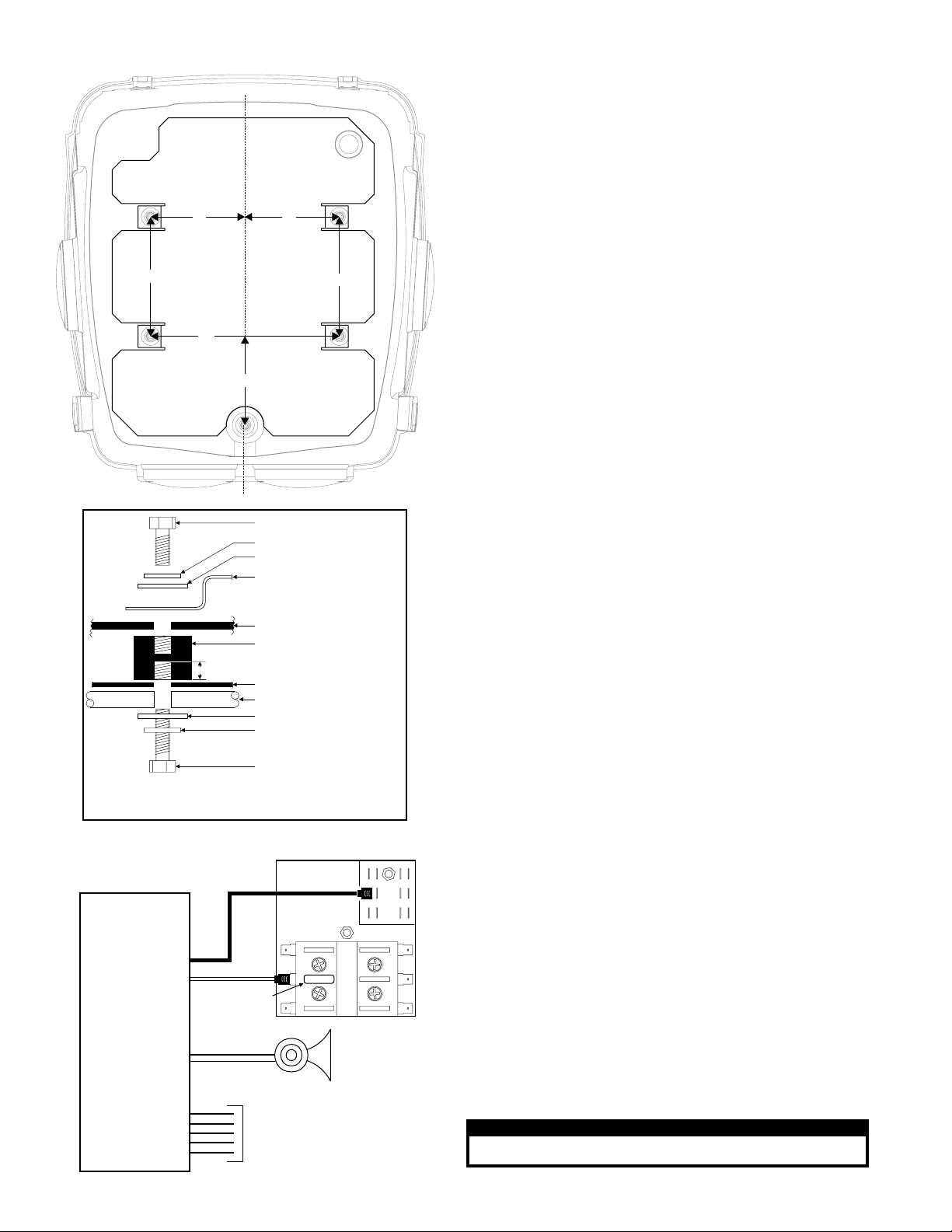
Mounting Hole Locations
C
L
6.37”
10”
4.75”
1/4-20 x 3/4” Hex Head Bolt
Internal Tooth Lockwasher
Flat Washer
Internal Mounting Plate
Mounting:
This box requires a mounting plate secured to the motorcycle’s luggage rack. If the bike is not
equipped with a mounting plate, one must be fabricated prior to installation of this box. Five
mounting holes (.281” dia.) are required to mount this box.
If the motorcycle is already equipped with a mounting plate, it may be necessary to drill the 5
mounting holes required for this installation.
Use the diagram shown to determine the precise location of these holes.
1. Position the box onto the mounting plate. Align the 5 vibration dampeners with the 5
5”5”
6.37”
mounting holes in the mounting plate.
2. Using the illustrations shown, secure the box to the mounting plate using the provided
hardware.
NOTE: Your luggage rack may already have the correct mounting holes drilled. Check
the measurements below and if these holes already exist at the proper distance,
remove any existing mounting hardware from the holes and secure the box with the
supplied mounting hardware.
3. Place the box into its mounting position on the deck and secure it with the
supplied mounting hardware as shown in the diagram.
Wiring:
Diagrams for optional equipment are shown below and on the following page. Refer to the
diagram(s) on the following page for general motorcycle box wiring information.
WARNING: All customer supplied wires that connect to the positive terminal of the
battery must be sized to supply at least 125% of the maximum operating current and be
FUSED at the battery to carry the load. DO NOT USE CIRCUIT BREAKERS WITH THIS
PRODUCT!
Operation:
Flash Pattern Selection: Lights must be switched on to use Scan-Lock™
TO CYCLE THROUGH ALL PATTERNS: Apply +12 volts to the WHT/VIO wire for less than 1
second and release to cycle forward. Apply +12 volts to the WHT/VIO wire for over 1 second
and release to cycle backward.
TO SET A PATTERN AS DEFAULT: When the desired pattern is displayed, allow it to run for
more than 5 seconds. The lighthead will now display this pattern when active.
Power Box (bottom)
Vibration Dampener
Note: Maximum bolt depth!
0.375”
Do not thread this bolt more than 0.375” into the vibration dampener!
*
Different hardware may be needed to ensure both proper mounting
and compliance with this requirement.
Siren Amplifier / Optional
Siren Amplifier
(optional)
Mounting Plate
Luggage Rack Tubing
Flat Washer
Internal Tooth Lockwasher
1/4-20 x 1 ½” Hex Head Bolt*
Fuse Block
FUSE
Fuse per
amplifier
manual
Siren
Speaker
To Customer Supplied Switches
(refer to the manual included
with your particular siren
amplifier for wiring information
and fusing)
TO RESET TO THE FACTORY DEFAULT PATTERN: Turn off power, apply +12 volts to the
WHT/VIO wire, then turn power on.
Note: If the installer wishes to connect the pattern selection wire (WHT/VIO) to a switch,
a momentary switch (normally open) is recommended.
Outlet Activation:
Apply +12VDC to a control wire(s) to activate the outlet. The outlet(s) remain active until
voltage is removed. Note: This flasher uses low current switching (100mA per control wire)
Low Power Operation:
Apply +12VDC to the VIO wire for Low Power Operation. Low Power Operation will remain in
effect until voltage is removed from the VIO wire. An SP/ST switch is recommended.
Flash Pattern Phase Modes:
The flasher used in this application has 3 different phase modes. Each pattern is available in
each mode. Each mode effects the relationship between each outlet: Phase 1 - 1, 3, 5 & 7
alternate with 2, 4, 6 & 8 Phase 2 - 1, 2, 3 & 4 alternate with 5, 6, 7 & 8 Phase 3 - All flash
simultaneously
Available Flash Patterns:
1. SignalAlert™ (Phase 1)
2. SignalAlert™ (Phase 2)
3. Signal Alert™ (Phase 3)
4. CometFlash® (Phase 1)
5. CometFlash® (Phase 2)
6. CometFlash® (Phase 3)
7. SingleFlash 75 (Phase 1)
8. SingleFlash 75 (Phase 2)
9. SingleFlash 75 (Phase 3)
10. SingleFlash 150 (Phase 1)
11. SingleFlash 150 (Phase 2)
12. SingleFlash 150 (Phase 3)
13. SingleFlash 375 (Phase 1)
14. SingleFlash 375 (Phase 2)
15. SingleFlash 375 (Phase 3)
16. DoubleFlash 75 (Phase 1)
17. DoubleFlash 75 (Phase 2)
18. DoubleFlash 75 (Phase 3)
19. ModuFlash™ (Phase 1)
20. ModuFlash™ (Phase 2)
21. ModuFlash™ (Phase 3)
22. ActionFlash™ (Phase 1)
23. ActionFlash™ (Phase 2)
24. ActionFlash™ (Phase 3)
25. ActionScan™ (Phase 1)
26. ActionScan™ (Phase 2)
27. ActionScan™ (Phase 3)
28. Invalid Pattern For This Application.
Do Not Use.
IMPORTANT WARNING!
CAUTION! DO NOT LOOK DIRECTLY AT THESE LED’S WHILE THEY ARE ON.
MOMENTARY BLINDNESS AND/OR EYE DAMAGE COULD RESULT!
Page 2
Page 3

POWER CONNECTOR
BUTT
SPLICE
40 AMP
Optional (See "Charger System" Above)
FUSE BLOCK NOTE:
Max. current draw per
circuit = 15A
BTT / GND / WHT
3 - GRN
2 - BLK
1 - RED
P5
(Fuse circuit @ 125%
of max. current draw)
12V BATTERY
Wiring Diagram
6 Light / M4 Split-LED
CHARGER
INLET
15A/120
VAC
3 - YEL
2 - BLK
1 - ORG
FUSE
P7
RED
+12VDC
12V BATTERY
Customer Supplied
BRAKE/TAIL/TURN
HARNESS
WHT / GROUND
YEL / LEFT TURN
GRN / RIGHT TURN
RED / BRAKE
BRN /TAIL
BLACK GND
Apply +12VDC to a control wire
to activate the outlet. The outlet
remains active until voltage is removed.
Note: This flasher uses low current
switching (100mA per control wire)
FLASHER CONTROL
WIRES
WHT/VIO / SCANLOCK
VIO / LOW POWER
BRN / OUTLETS 1 & 2
RED / OUTLETS 3 & 4
ORG / OUTLETS5&6
YEL / OUTLETS 7 & 8
10 AMP
POS NEG
3 - RED
2 - BLK
1 - GRN
P4
BLK
RED
21
FUSE BLOCK
3 AMP FUSE
Optional Equipment:
Charger System:
POWER
CONNECTOR
POWER
CONNECTOR
BLACK GROUND
RED
+ 12 VOLTS DC
POWER CONNECTOR
BLACK GROUND
+ 12 VOLTS DC
RED
Fuse Block
10 AMP
P1
3-VIO
1-GRY
2 - BLK
P2
BUTT SPLICE
FUSE BLOCK
40 AMP FUSE
WIRE COVER
CHARGER
12V BATTERY
Customer Supplied
12V BATTERY
Optional
Optional
1 - BRN
2 - BLK
3 - BLU
P3
Flasher Control Connector
(Rear View)
3
12
5
6
4
4
3 - ORG
2 - BLK
1 - YEL
13
Output
P6
Indicators
1
3
4
2
1
2
FLASHER
6
8
6
5
7
1 - WHT/VIO /
2 - VIO /
Low Power
3 - BRN /
Outlets 1&2
4 - RED /
Outlets 3&4
5 - ORG /
Outlets 5&6
6-YEL/
Outlets 7&8
Lighthead Connector
(Rear View)
5
7
6
8
16
15
11121314
1 - BLU
9 - GRN
2-GRY
10 - VIO
3 - BLK
11 - BLK
4 - BLK
12 - N/C
5 - N/C
13 - BLK
6 - BLK
14- BLK
7 - BRN
15 - RED
8 - ORG
16 - YEL
Power Connector
(Rear View)
1
2
1
- +12VDC (RED)
Fuse @ 10 Amp
-
2
- Ground (BLK)
- ™
Scan Lock
1
234
9
10
Wiring Diagram
6 Light / M4 LED
NOT USED
BRN
P1
BLK
P2
GRY
BLK
YEL
P9
BLK
ORG
P8
BLK
P4
BLK
P6
GRN
Lighthead Connector
(Rear View)
5
7
6
8
16
15
1 - BLU
2-GRY
BLK
P7
RED
3 - BLK
4 - BLK
5 - BLK
6 - BLK
7 - BRN
8 - ORG
234
10
11121314
9 - GRN
10-VIO
11 - BLK
12 - BLK
13 - BLK
14- BLK
15 - RED
16 - YEL
1
9
CUSTOMER
SUPPLIED
FUSE BLOCK
3 AMP FUSE
CHARGER
CHARGER INLET
15A/120 VAC
Page 3
BLK
P3
VIO
BLK
P5
BLU
 Loading...