

Page 1

®
ENGINEERING COMPANY INC.
51 Winthrop Road
Chester, Connecticut 06412-0684
Installation Guide:
LFL Liberty Mini Edge
Phone: (860) 526-9504
Fax: (860) 526-4078
Internet: www.whelen.com
Sales e-mail: autosale@whelen.com
Canadian Sales e-mail: autocan@whelen.com
Customer Service e-mail: custserv@whelen.com
Safety First
This document provides all the necessary information to allow your Whelen product to be properly and safely installed.
Before beginning the installation and/or operation of your new product, the installation technician and operator must
read this manual completely. Important information is contained herein that could prevent serious injury or damage.
• Proper installation of this product requires the installer to have a good understanding of automotive electronics,
systems and procedures.
• If mounting this product requires drilling holes, the installer MUST be sure that no vehicle components or other
vital parts could be damaged by the drilling process. Check both sides of the mounting surface before drilling
begins. Also de-burr any holes and remove any metal shards or remnants. Install grommets into all wire
passage holes.
®
• If this manual states that this product may be mounted with suction cups, magnets, tape or Velcro®, clean the
mounting surface with a 50/50 mix of isopropyl alcohol and water and dry thoroughly.
• Do not install this product or route any wires in the deployment area of your air bag. Equipment mounted or
located in the air bag deployment area will damage or reduce the effectiveness of the air bag, or become a
projectile that could cause serious personal injury or death. Refer to your vehicle owner’s manual for the air bag
deployment area. The User/Installer assumes full responsibility to determine proper mounting location, based
on providing ultimate safety to all passengers inside the vehicle.
• For this product to operate at optimum efficiency, a good electrical connection to chassis ground must be
made. The recommended procedure requires the product ground wire to be connected directly to the NEGATIVE
(-) battery post.
• If this product uses a remote device to activate or control this product, make sure that this control is located in
an area that allows both the vehicle and the control to be operated safely in any driving condition.
• Do not attempt to activate or control this device in a hazardous driving situation.
• This product contains either strobe light(s), halogen light(s), high-intensity LEDs or a combination of these
lights. Do not stare directly into these lights. Momentary blindness and/or eye damage could result.
• Use only soap and water to clean the outer lens. Use of other chemicals could result in premature lens cracking
(crazing) and discoloration. Lenses in this condition have significantly reduced effectiveness and should be
replaced immediately. Inspect and operate this product regularly to confirm its proper operation and mounting
condition. Do not use a pressure washer to clean this product.
• It is recommended that these instructions be stored in a safe place and referred to when performing
maintenance and/or reinstallation of this product.
• FAILURE TO FOLLOW THESE SAFETY PRECAUTIONS AND INSTRUCTIONS COULD RESULT IN DAMAGE TO
THE PRODUCT OR VEHICLE AND/OR SERIOUS INJURY TO YOU AND YOUR PASSENGERS!
Automotive: Lightbars
For warranty information regarding this product, visit www.whelen.com/warranty
©2003 Whelen Engineering Company Inc.
Form No.13764J (091510)
Page 1
Page 2
IMPORTANT! The lightbar should be a minimum
of 16" from any radio antennas!
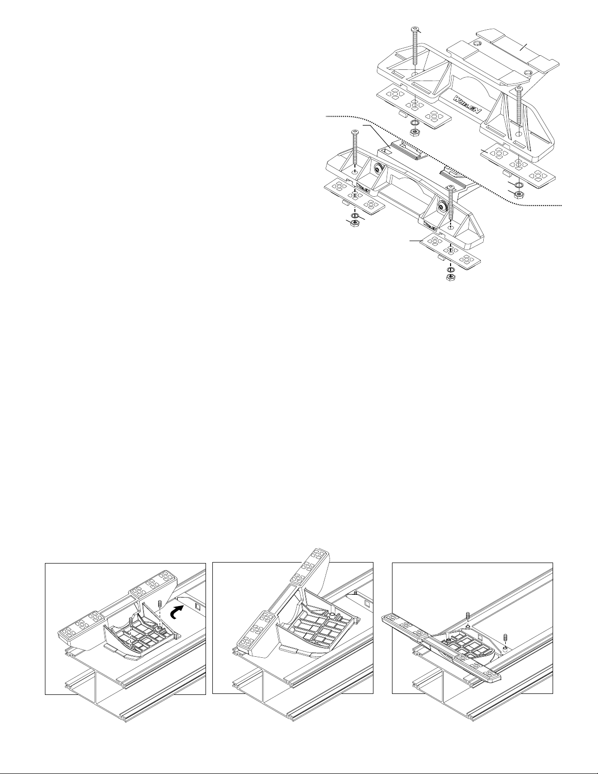
Permanent Mounting:
1. Locate the mounting foot and plate included with your lightbar. If not already
present, install the mounting plate onto the foot. When properly positioned, this
plate is centered from side-to-side on the mounting foot.
2. Flip the lightbar upside-down to expose the bottom of the extrusion and place
the mounting foot onto the extrusion.
3. Rotate the mounting foot 90° in a counter-clockwise direction. Make sure that
the edges of the mounting foot swing into position under the extrusion
mounting lip.
4. Repeat this procedure for the remaining mounting foot and return the lightbar
to its right side-up position.
5. Position the lightbar onto the vehicle roof in the desired mounting location. One
often selected location is directly above the B-pillars. This area is the strongest
part of the roof. Refer to your lightbar manual for cable exit location, to be sure
that the lightbar is facing the proper direction.
6. Adjust the two mounting feet outwards so that they are as close to the edge of
the roof as possible. Make sure that both mounting feet are in full contact with
the roof. Be sure that there is no less than 1/2” clearance between the roof and
the lightbar at the closest point. With the mounting feet in their proper position,
lightly tighten the foot allen head set screws.
7. Turn the lightbar upside-down and firmly tighten all of the set screws from step
6 (2 or 4 per side).
8. Note that on the adjustable foot, use the hole in the pad as a guide to drill the
two holes into the mounting foot at the locations shown.
9. Place the lightbar in its final mounting position on the vehicle, mark the
mounting hole locations off onto the mounting surface, remove the lightbar and
drill the mounting holes.
Standard
Mounting
BoltBolt
Mounting
Plate
Foot
Mounting
Plate
Nut
10. Place the lightbar back onto the vehicle lined up with the mounting holes and
secure the mounting feet to the vehicle using the supplied hardware.
Washer
Mounting
Pad
Mounting
Pad
Washer
Nut
Adjustable
Mounting
Foot
Strap Mounting:
1. Locate the mounting foot, mounting plate and tinnerman plate included with
your lightbar. If not already present, install the mounting plate onto the
mounting foot. When properly positioned, this plate is centered from side-toside on the mounting foot.
2. Flip the lightbar upside-down to expose the bottom of the extrusion and place
the mounting foot onto the extrusion.
3. Rotate the mounting foot 90° in a counter-clockwise direction. Make sure that
the edges of the mounting foot swing into position under the extrusion
mounting lip. Install a tinnerman plate onto the extrusion in the same manner.
4. Repeat this procedure for the remaining mounting foot and tinnerman plate and
return the lightbar to its right side-up position.
5. Position the lightbar onto the vehicle roof in the desired mounting location. One
often selected location is directly above the B-pillars. This area is the strongest
part of the roof. Refer to your lightbar manual for cable exit location, to be sure
that the lightbar is facing the proper direction.
6. Adjust the two mounting feet outwards so that they are as close to the edge of
the roof as possible. Both mounting feet must be in full contact with the roof. Be
sure that there is no less than 1/2” clearance between the roof and the lightbar
at their closest point. With the mounting feet in their proper position, lightly
tighten the foots allen head set screws.
7. Return the lightbar to an upside-down position. Slide each tinnerman plate
outwards until it is fully engaged with its corresponding mounting foot. With the
Insert foot into extrusion with locking plate
attached.
Twist mounting foot into
position
mounting feet and tinnerman plates in their proper positions firmly tighten all of
the set screws (2 or 4 per side). Flip the lightbar right side-up and return it to its
mounting position.
8. Open both drivers side doors. In the area directly below the mounting foot,
carefully pull the drivers side weatherstrip away from the vehicle. Remove
enough so that the area where the mounting strap will be secured to the
vehicle is exposed. Repeat procedure for passenger side.
9. Insert the mounting strap through the mounting foot. Be sure that the strap fits
flush against the area where it will be secured onto the vehicle. Insert the
tension bolt through the mounting strap and into the tinnerman nut on the
tinnerman plate. Tighten slightly with a long shafted, Phillips screwdriver.
Repeat procedure for passenger side.
10. If your mounting strap has mounting holes in the end of the strap, use these
holes as a template to drill appropriately sized pilot holes through the strap and
into the vehicle. Repeat for passenger side of the vehicle.
11. Firmly tighten the tension bolts to secure the lightbar to the vehicle.
NOTE: Model MKAJ is an adjustable mounting foot. You may loosen the
screws on the rear of the foot and adjust the angle of the lightbar. This feature
can be used if the angle of the roof is not level with the road.
IMPORTANT: To adjust the leveling screws you must use a torque wrench set
at 35 to 40 in./lbs.
Loosely secure foot and locking plate.
ANCHOR
PLATE
Page 2
Page 3

Standard Mounting Foot / Model MKEZ
Adjustable Mounting Foot / Model MKAJ
Tension
Bolt
Mounting
Screw
Mounting
Pad
Mounting
5" Mounting Foot
METAL SCREW
SHEET
METAL
SCREWS
NOTE: The mounting straps are made to fit the contours of individual
vehicles. The strap
NOTE:
for your vehicle
NOTE:
Foot
BOLT
STRAP
Mounting
Strap
Tinnerman
Plate
Mounting
Plate
shown here is for example only. The strap
may look different.
Tighten screws
with torque
set at 35 to 40 in/lbs
MOUNTING FOOT
EXTENSION
NUT
SPLIT LOCK
WASHER
wrench
TINNERMAN
NUT
FOOT
ANCHOR
PLATE
VEHICLE ROOF
Mounting
Screw
Adjustment
Plate slides into
lightbar extrusion
SET
SCREW
Tension
screws
Bolt
Lock
Washer
Mounting
Strap
Locking
Plate
Tinnerman
Plate
Nut
Mounting
Foot
Mounting
Pad
CAUTION: Permanent mounting will require drilling. The installer must be sure that no
vehicle components or other vital parts will be damaged. Be aware of the location of
any front, side or upper air bags.
CAUTION: There may be a roof support member that spans the distance between the
driver’s and passenger ’s side. Do not drill through this member. Adjust the location of
the cable access hole until the hole can be drilled without contacting this support
member.
with
DRILLING THE CABLE ACCESS HOLE
FRONT OF LIGHTBAR
For
lightbars
cables exiting
the Driver-side
of the extrusion
For
lightbars
cables exiting
with
the Passenger-side
of the extrusion
IMPORTANT! It is the responsibility of the installation technician to make sure that the
installation and operation of this product will not interfere with or compromise the
operation or efficiency of any vehicle equipment!
Drill cable access hole in appropriate area
for your lightbar (see note)
CAUTION: Using a magnetic mounted light on the outside of a vehicle, while in motion,
is not recommended and is at the sole risk of the user.
Installation:
1. To protect the headliner from damage caused by
1/2" Minimum Clearance at Closest Point
NOTE: Unless otherwise specified, the lightbar mounting feet must be sitting as close to the
edge of the roof as possible. Mounting feet must also be in full contact with the roof and not
be hanging off the edge.
the vehicle. Use RTV silicone to weatherproof the access hole after the cable(s) are pulled into the vehicle.
4. When routing the cable(s), be sure to use a path that avoids any vehicle components or other vital parts that may be damaged. Also be careful not to interfere with any
vehicle air bags (front, side, etc.). Route the cable(s) towards your switch panel and refer to the instructions included with the switch panel for wiring information.
Page 3
drilling the cable access hole through the vehicle roof,
allow a 5” to 7” distance between roof and headliner
by lowering the headliner before drilling.
2. Using a 1” hole saw, drill the cable access hole. Use a
round file to smooth and de-burr the edges and insert
a 1” grommet (user supplied).
3. Insert the cable(s) through the cable access hole into
Page 4

Replace
fuse
here
Wiring:
The cigarette plug model plugs it into your cigarette lighter and requires no further
wiring.
If you have a lightbar that has an 11-conductor cable, refer to the chart below for
important wiring information.
NOTE: For internal fuse replacement see information on next page.
WARNING! All customer supplied wires that connect to the positive terminal of
the battery must be sized to supply at least 125% of the maximum operating
current and FUSED
BREAKERS WITH THIS PRODUCT!
at the battery to carry that load. DO NOT USE CIRCUIT
WIRE COLOR (VOLTAGE) FUNCTION FUSE @
RED (+12VDC) . . . . . . . . . . .LED Flasher (+) Positive . . 5 Amps
BLK / YEL (+12VDC) . . . . . .Scan-Lock™. . . . . . . . . . . . . 1 Amp
GRY (+12VDC) . . . . . . . . . . .Front Corner LEDs . . . . . . . . 1 Amp
WHT (+12VDC) . . . . . . . . . . .Halogen 1 . . . . . . . . . . . . . . 5 Amps
WHT/BLK (+12VDC) . . . . . .Inboard LEDs . . . . . . . . . . . 5 Amps
YEL (+12VDC) . . . . . . . . . . .Halogen 2 . . . . . . . . . . . . . . 5 Amps
WHT / BLU (+12VDC) . . . . .Rear Corner LEDs . . . . . . . . 1 Amp
BLK / WHT (-) . . . . . . . . . . . .Halogen 1 & 2 Ground . . . . . . . N/A
WHT / VIO (+12VDC) . . . . . .Endcap LEDs . . . . . . . . . . . . 1 Amp
VIO (+12VDC). . . . . . . . . . . .Low Power . . . . . . . . . . . . . . 1 Amp
BLK (-) . . . . . . . . . . . . . . . . .LED Flasher (-) Negative . . . . . N/A
Hi/Low Control:
Option 1: Latching Mode: By applying +voltage to the VIOLET wire for less than 1
sec., the power supply is “latched” into Low power operation. The unit must be turned
off and then back on to restore normal, Hi power operation. A momentary switch is
best for this method.
Option 2: Level Mode: Applying +voltage to the VIOLET wire for more than 1 sec.
holds the power supply in Low power mode until that voltage is removed. A toggle
switch is best for this method.
Scan-Lock™:
To cycle forward through all patterns: Apply power to the control wire of the
function you want to change, then apply power to the BLK/YEL (Scan-Lock™) wire
for less than 1 second and release. This will change the pattern. Repeat for next
pattern.
To choose a pattern: While cycling through the patterns, when you find the pattern
you want let it run for more than 5 seconds and it will lock in and become the default
pattern.
To reset to the factory default pattern: Turn off power. While applying power to the
Scan-Lock™ wire, turn power on to the light(s) you want to reset.
Scan-Lock can be connected to a customer supplied SPST switch.
Corners / Cross Corners / Alternating
NOTE: The available flash patterns are
shown here. This will show how FRONT
LEDs (optional) and CORNER LEDs
react to Alternating and Cross flash patterns.
Available Flash Patterns:
1A
SignalAlert™
B
1
SignalAlert™
C
1
SignalAlert™
2A
CometFlash
B
2
CometFlash
C
2
CometFlash
3A
DoubleFlash
B
3
DoubleFlash
C
3
DoubleFlash
4A
SingleFlash
B
4
SingleFlash
C
4
SingleFlash
6
SteadyFlash
7
Steady
3 cycles of 1A & 3 cycles of 1B
®
®
®
3 cycles of 1A & 3 cycles of 1B
3 cycles of 1A & 3 cycles of 1B
3 cycles of 1A & 3 cycles of 1B
Alternating
Cross
Alternating
Cross
Alternating
Cross
Alternating
Cross
1 & 2 Steady 3 & 4
SingleFlash (SIM.)
1, 2, 3 & 4 Steady
Wiring Diagram
CORNER LED #3
GREEN
WHT/ORG
500 LED #1
BLUE
WHT/BRN
WHITE
BLACK
500 HALO. #1
BLUE
WHT/BRN
CORNER LED #1
AB
500 HALOGEN #2
Replace
Replace
fuse here
fuse here
YELLOW
BLACK
Front of Lightbar (4 Light Shown)
500 HALO. #1
WHITE
BLACK
10
FUSE
10AMP
Installing Lens and Lighthead
Housing into extrusion
500 LED #3
GREEN
WHT/ORG
444645
GREEN
WHT/RED
500 LED #2
Lens
fits
here
47
CORNER LED #2
GREEN
WHT/RED
BLUE
WHT/YLW
CORNER LED #4
48
500 LED #4
BLUE
WHT/YEL
YELLOW
BLACK
500 HALOGEN #2
Top and bottom of extrusion
secure to Support Bracket.
SUPPORT
BRACKET
Servicin our Li htbargy g
Use the illustrations shown if you
need to gain access to the lightbar
to service or replace parts.
With
Alley
Light
#6x5/8"PPH
PLAST-LOC
Without
Alley
Light
#6-32 x 5/8"
PPHMS
Installing Corner Linear-LED®
Lighthead into extrusion
#6-32 ELASTIC
STOP NUT
Installing a lighthead
into its housing
Insert the tabs on the lighthead housing,
into the channels in the extrusion.
Page 4
Insert the tabs on the lighthead housing,
into the channels in the extrusion.
Page 5

QTY QTYQTY QTY
11
141
4
4
4
4
A/R
A/R
A/R
A/R
A/R
A/R
A/R A/R A/R A/R
4
A/R
11
1
1
1
1
1
1
1
1
1
1
2
2
111
2211
2
2
2
A/R
A/R2A/R
A/R
A/R A/R
A/R
A/R
A/R
A/R
A/R
A/R
1
121
4
4
212
22
4
4
4
4
4
4
2
2
242
A/R
A/R
A/R
ITEM
PART NUMBER
01-0684207-( )
01-0684207-( )
01-0684207-( )
01-0684207-( )
1
11-363336-017
2
08-0640834-01
3
65-0010192-00
4
14-130216-100
5
66-0715403-00
6
46-0742901-00
7
21-11245004-1
1
8
14-104216-080
1
9
13-104111-063
1
10
26-0115037-07
12
11-443158-000
13
02-0169672-00 FLASHER, LIGHTBAR LED
14
11-483564-000
15
02-0383577-03
16
01-026B625210
17
01-026B625220
18
01-026B625230
19
01-026B625240
20
01-026B625250
11-26B607-017
21
15-065419-080
2
22
23
68-1983818-30
24
02-0342791-30
25
4
68-1983819-30
26
38-0283572-00
PERM MT (Liberty™) 4 LED LIGHTHEADS
MAG MT ( ) 4 LED LIGHTHEADSLiberty™
PERM MT ( ) 8 LED LIGHTHEADSLiberty™
MAG MT ( ) 8 LED LIGHTHEADSLiberty™
BASE EXTRUSION
MOUNTING PAD
MAGNET X-80
1/4-20 x 5/8" PPHMS
THREADLOCKER, LOCTITE 242
INPUT CABLE ASS'Y. (11C COMPOSITE)
GROMMET, 1.562"
SCREW, 10-24 x 1/2" PPHMS
#10-24 WHIZ NUT
CABLE CLAMP, 7/16"
HOUSING, LED FLASHER
HOUSING, LIGHTHEAD (SNAP-IN)
SUB-ASS'Y., 500 HALOGEN W/3 POS.
ASS'Y-CORNER LINEAR (12) LED -AMBER
ASS'Y-CORNER LINEAR (12) -BLUELED
ASS'Y-CORNER LINEAR (12) -WHITELED
ASS'Y-CORNER LINEAR (12) -GREENLED
ASS'Y-CORNER LINEAR (12) -REDLED
TOP EXTRUSION
SCREW, 6 X 1/2 PPH PLASTI-
LENS, 5-1/16" (CLEAR)
ASS'Y., LENS DIVIDER
LENS, 5-11/16" (CLEAR)
GASKET, ENDCAP
DESCRIPTION
QTY QTYQTY QTY
2
2
2
A/R
A/R
A/R2A/R
A/R
A/R
A/R A/R
4
4
212
1
11
1
1
8
8
8
1
1
1
4
4
4
1
1
1
1
44
44
2
2
2
1
2
1
1
1
2
2
1
A/R1A/R
A/R
A/R
A/R
A/R
A/RA/R
A/R
A/R
A/R
A/R
A/R
A/R
A/R
A/R
A/R
A/R
A/R
A/R
A/R
A/R
A/R
A/R
2
2
2
4
4
4
ITEM
28
29
30
31
32
33
34
35
8
36
1
37
4
38
1
39
1
40
22
41
2
42
2
43
1
44
1
45
46
47
48
49
50
51
52
53
54
55
2
56
4
PART NUMBER
68-1963237-30
15-065410-100
14-062216-100
13-062120-052
26-0115037-04
02-0240837-01
10-0220700-02
14-104286-16J
39-0416323-04
20-0042765-00
10-0522960-00
01-0483969007
13-062111-053
14-062116-120
09-1363542-00
20-0608089304
46-0784200-02
46-0784200-03
46-0784200-00
46-0784200-01
46-0763985-01
01-026B827650
01-026B827640
01-026B827630
01-026A068220
01-026B827610
10-0323206-00
02-036B855-00
14-104216-06J
LENS, 500 SERIES OPTIC (CLEAR)
DESCRIPTION
#6 x 5/8" PPH PLAST-LOC
#6-32 x 5/8" PPHMS
#6-32 ELASTIC STOP NUT
CABLE CLAMP, 1/4"
INPUT CABLE ASS'Y. CIGAR PLUGwith
LABEL, CAUTION-MAGNET MTG.
#10-24 x 1-1/4" TX. PHD. SHOULDERwith
16 POS SOCKET
SPACER, CORNER RETENTION
LABEL, MODEL & SERIAL NO.
MOUNTING KIT 7S
NUT / 6-32 X 5/16 WHIZ LOCK
SCREW / 6-32 X 3/4 PFMS
FILLER PANEL / 500 SERIES
SPACER / 3/16 LG X 1/4 OD X .166 ID
HARNESS / 4 LED POWER/CONTROL / 11C
HARNESS / 4 LED POWER/CONTROL / CIG
HARNESS / 8 LED POWER/CONTROL / 11C
HARNESS / 8 LED POWER/CONTROL / CIG
HARNESS / 4 LED / 30"
LINEAR 500 LED RED
LINEAR 500 LED GREEN
LINEAR 500 LED WHITE
LINEAR 500 LED BLUE
LINEAR 500 LED AMBER
LABEL, NASCAR BAR LOGO CLEAR
SUB ASSY, END SUPPORT BRACKET
SCREW, 10-24 X 3/8 PPH TRILOBULAR
12
35 26 25
43
31
13
40
41
12
10
21
16
18
17
19
24
REAR OF LIGHTBAR
23
14
20
8-LT
VERSION
ONLY
37
12
36
1
15
49 50 51
2
52 53
3
36
4
22
POS. 16-BLK
Smooth
POS. 1-BLK
6
Grooved
55
56
33
Page 5
 Loading...