

Page 1

®
ENGINEERING COMPANY INC.
51 Winthrop Road
Chester, Connecticut 06412-0684
Phone: (860) 526-9504
Fax: (860) 526-4078
Internet: www.whelen.com
Sales e-mail: autosale@whelen.com
Canadian Sales e-mail: canadiansales@whelen.com
Customer Service e-mail: custserv@whelen.com
Installation Guide:
L22 LED Beacon (Encapsulated)
Models L22H*** and L22L***
Whelen’s emergency vehicle warning devices must be properly mounted and wired in order to be effective and safe. Read and follow all of Whelen’s
written instructions when installing or using this device. Emergency vehicles are often operated under high speed stressful conditions which must be
accounted for when installing all emergency warning devices. Controls should be placed within convenient reach of the operator so that he can operate
the system without taking his eyes off the roadway. Emergency warning devices can require high electrical voltages and/or currents. Properly protect and
use caution around live electrical connections.Grounding or shorting of electrical connections can cause high current arcing, which can cause personal
injury and/or vehicle damage, including fire. Many electronic devices used in emergency vehicles can create or be affected by electromagnetic
interference. Therefore, after installation of any electronic device it is necessary to test all electronic equipment simultaneously to insure that they operate
free of interference from other components within the vehicle. Never power emergency warning equipment from the same circuit or share the same
grounding circuit with radio communication equipment. All devices should be mounted in accordance with the manufacturer’s instructions and securely
fastened to vehicle elements of sufficient strength to withstand the forces applied to the device. Driver and/or passenger air bags (SRS) will affect the way
equipment should be mounted. This device should be mounted by permanent installation and within the zones specified by the vehicle manufacturer, if
any. Any device mounted in the deployment area of an air bag will damage or reduce the effectiveness of the air bag and may damage or dislodge the
device. Installer must be sure that this device, its mounting hardware and electrical supply wiring does not interfere with the air bag or the SRS wiring or
sensors. Mounting the unit inside the vehicle by a method other than permanent installation is not recommended as unit may become dislodged during
swerving; sudden braking or collision. Failure to follow instructions can result in personal injury. Whelen assumes no liability for any loss resulting from the
use of this warning device. PROPER INSTALLATION COMBINED WITH OPERATOR TRAINING IN THE PROPER USE OF EMERGENCY WARNING
DEVICES IS ESSENTIAL TO INSURE THE SAFETY OF EMERGENCY PERSONNEL AND THE PUBLIC.
Warnings to Users
Warnings to Installers
Whelen’s emergency vehicle warning devices are intended to alert other operators and pedestrians to the presence and operation of emergency vehicles
and personnel. However, the use of this or any other Whelen emergency warning device does not guarantee that you will have the right-of-way or that
other drivers and pedestrians will properly heed an emergency warning signal. Never assume you have the right-of-way. It is your responsibility to proceed
safely before entering an intersection, driving against traffic, responding at a high rate of speed, or walking on or around traffic lanes. Emergency vehicle
warning devices should be tested on a daily basis to ensure that they operate properly. When in actual use, the operator must ensure that both visual and
audible warnings are not blocked by vehicle components (i.e.: open trunks or compartment doors), people, vehicles, or other obstructions. It is the user’s
responsibility to understand and obey all laws regarding emergency warning devices. The user should be familiar with all applicable laws and regulations
prior to the use of any emergency vehicle warning device. Whelen’s audible warning devices are designed to project sound in a forward direction away
from the vehicle occupants. However, because sustained periodic exposure to loud sounds can cause hearing loss, all audible warning devices should be
installed and operated in accordance with the standards established by the National Fire Protection Association.
Safety First
This document provides all the necessary information to allow your Whelen product to be properly and safely installed. Before beginning the installation
and/or operation of your new product, the installation technician and operator must read this manual completely. Important information is contained herein
that could prevent serious injury or damage.
• Proper installation of this product requires the installer to have a good understanding of automotive electronics, systems and procedures.
• Whelen Engineering requires the use of waterproof butt splices and/or connectors if that connector could be exposed to moisture.
• Failure to use specified installation parts and/or hardware will void the product warranty.
• If mounting this product requires drilling holes, the installer MUST be sure that no vehicle components or other vital parts could be damaged
by the drilling process. Check both sides of the mounting surface before drilling begins. Also de-burr the holes and remove any metal shards
or remnants. Install grommets into all wire passage holes.
• If this manual states that this product may be mounted with suction cups, magnets, tape or Velcro®, clean the mounting surface with a 50/50
mix of isopropyl alcohol and water and dry thoroughly.
• Do not install this product or route any wires in the deployment area of your air bag. Equipment mounted or located in the air bag deployment
area will damage or reduce the effectiveness of the air bag, or become a projectile that could cause serious personal injury or death. Refer to
your vehicle owner’s manual for the air bag deployment area. The User/Installer assumes full responsibility to determine proper mounting
location, based on providing ultimate safety to all passengers inside the vehicle.
• For this product to operate at optimum efficiency, a good electrical connection to chassis ground must be made. The recommended
procedure requires the product ground wire to be connected directly to the NEGATIVE (-) battery post (this does not include products that use
cigar power cords).
• If this product uses a remote device for activation or control, make sure that this device is located in an area that allows both the vehicle and
the device to be operated safely in any driving condition.
• Do not attempt to activate or control this device in a hazardous driving situation.
• This product contains either strobe light(s), halogen light(s), high-intensity LEDs or a combination of these lights. Do not stare directly into
these lights. Momentary blindness and/or eye damage could result.
• Use only soap and water to clean the outer lens. Use of other chemicals could result in premature lens cracking (crazing) and discoloration.
Lenses in this condition have significantly reduced effectiveness and should be replaced immediately. Inspect and operate this product
regularly to confirm its proper operation and mounting condition. Do not use a pressure washer to clean this product.
• It is recommended that these instructions be stored in a safe place and referred to when performing maintenance and/or reinstallation of this
product.
• FAILURE TO FOLLOW THESE SAFETY PRECAUTIONS AND INSTRUCTIONS COULD RESULT IN DAMAGE TO THE PRODUCT OR VEHICLE
Automotive: Beacons
AND/OR SERIOUS INJURY TO YOU AND YOUR PASSENGERS!
©2009 Whelen Engineering Company Inc.
Form No.14335B (061214)
For warranty information regarding this product, visit www.whelen.com/warranty
Page 1
Page 2
Electrical Specifications
.35 AmpsPeak:
.75 ampsPeak:
SignalAlert™ / Sim.
Input Current
Input Voltage
Power
12.8 VDC ± 20%
12V
25.6 VDC ± 20%
24V
Avg: .14 amps.3 ampsAvg:
Default Flash Pattern SignalAlert™ / Sim.
SPST
switch
Momentary switch
3 AMP
Fuse
Connect to SYNC wire of
other beacon or Cut & cap
GREY wire
RED
BLK
WHT/VIO
GREY
BATTERY
PERMANENT
MOUNT
"J" HOOK
MOUNT
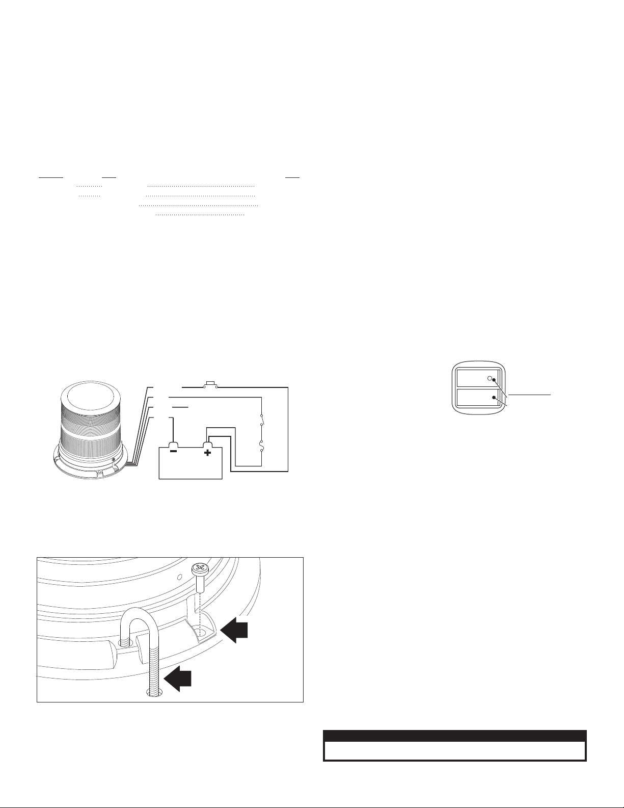
Fig. 1
The L22 Beacon has fully encapsulated electronics that are impervious to
NOTE: The cigar cord adaptor
is equipped with an 8 Amp fuse.
Use a replacement fuse with an
identical value.
Switch Functions:
SW1 = ON/OFF
SW2 = Scan-Lock™ / Momentary
(
12 volt model only
)
CAUTION! DO NOT LOOK DIRECTLY AT THESE LED’S WHILE THEY ARE ON.
MOMENTARY BLINDNESS AND/OR EYE DAMAGE COULD RESULT!
IMPORTANT WARNING!
damage from moisture and vibration. Some beacons feature an automatic
photocell High Power override. This beacon also features Scan-Lock™ to
choose between 25 available flash patterns. 6 mounting options are
available: mirror mount (Optional), permanent mount, pipe mount, J-hook
mount, magnetic mount and Vacuum mount. (Magnetic and Vacuum
mount models do not include SYNC) All models are SAE certified.
IMPORTANT! All beacons in this manual should be fused at 3 AMPS.
IMPORTANT! Always be sure the drain hole (located on the bottom of
the base) is facing the rear of the vehicle after mounting.
WARNING: All customer supplied wires that connect to the positive
terminal of the battery must be sized to supply at least 125% of the
maximum operating current and FUSED at the battery to carry the
load. DO NOT USE CIRCUIT BREAKERS WITH THIS PRODUCT!
Wiring:
Listed below are the wire designations for the L22 beacon. To extend the
beacons wires, use the wire gauge indicated.
WIRE COLOR . . . . . . . . . . WIRE GAUGE . . . . . . . . . . . . . . .FUNCTION
RED. . . . . . . . . . . . . . . . . . 18 AWG . . . . . . . . . . . . . . . . . . . . . . .Positive
BLACK . . . . . . . . . . . . . . . 18 AWG . . . . . . . . . . . . . . . . . . . . . . . Ground
GREY . . . . . . . . . . . . . . . . 18 or 22 AWG. . . . . . . . . . . . . . . . . . . . SYNC
WHITE-VIOLET. . . . . . . . . 18 or 22 AWG . . . . . . . . . . . . . . .Scan-Lock™
2. Drill the mounting holes with a #16 drill bit. Drill the wire access hole
using a 3/8” drill bit. Remove any burrs from the wire access hole and
It is also recommended that you install a rubber grommet (customer
supplied) into the wire hole to protect the wires.
3. A base seal is used between the beacon base and mounting surface.
4. Feed the wires first through the base seal and then through the cable
access hole and place the base (with seal) on the mounting surface
(while lining up the mounting holes in the base with the mounting
holes you drilled into the mounting surface). Secure the beacon
firmly to the mounting surface with the supplied mounting screws.
1 Inch (NPT) Pipe Mount:
Threading for a 1 inch (NPT) pipe mounting is precast in the base
(pipe not included with beacon).
1. Feed power cable through the 1 inch pipe and connect the cable to
the wires of the beacon.
2. Screw the beacon into the threads on the 1” pipe, taking precaution
not to damage the connected power wires. Do not tighten base too
hard as not to damage threads on base.
Temporary Mounting (Optional):
IMPORTANT WARNING: The use of any magnetically mounted
warning device on the outside of a vehicle in motion is not
recommended and is at the sole risk and responsibility of the user.
Magnetic/suction: Thoroughly clean the proposed mounting surface prior
to mounting. For suction cup mounting, wipe the suction cup clean, place
the beacon onto its mounting surface and apply gentle pressure to ensure
a good seal has been achieved. Magnetic/Suction Cups mount the same
as standard suction cups but are
best suited to a flat, steel surface.
Magnetic: Place the beacon onto
the mounting surface and plug it
into the vehicle cigar lighter.
Magnetic mount models do not
offer SYNC.
Mounting:
“J” Hook Mount:
This beacon is equipped to handle the “J” hook mount available on some
beacons. Be sure to use the correct “J” hook mounting holes (Fig. 1).
PERMANENT MOUNT:
1. Use the base as a template and mark the three mounting holes off
onto the mounting surface. Remove base. In the center between the
three mounting holes, mark the location of the wire access hole.
Operation: SYNC:
To SYNC two beacons, configure both beacons to display the same
Phase 1 (Simultaneous) pattern. Turn the power off and connect the
GREY wire from each beacon together. When the beacons are activated
their patterns will be synchronized. To configure two beacons to alternate
their patterns, advance the pattern of either beacon to Phase 2
(Alternating) of the current pattern. (Not available on cigar plug models)
Hi/Lo Power: Photocell
If this beacon is equipped with photocell Hi-Lo, the beacon will
automatically step down to low power at night. This feature is optional.
Programming / Scan-Lock™ / White-Violet:
To cycle forward through all patterns: With the beacon switched on,
apply Positive (+) voltage to the WHT-VIO wire for less than 1 second and
release. To cycle backward through all patterns: Apply Positive (+)
voltage to the WHT-VIO wire for more than 1 second and release.
To set a pattern as default: When the desired pattern is displayed, allow
it to run for more than 5 seconds. The beacon will now display this pattern
when activated.
To reset to the factory default pattern: Turn off power. Now, while
applying Positive (+) voltage to the WHITE-VIOLET wire, turn power on.
NOTE: Cigar cord models have a momentary switch on the plug to
control Scan-Lock™ as well as an On-Off switch.
Page 2
Page 3
68-2180483-50
68-2180483-40
68-2180483-20
01-06860243_2
01-06860244_2
01-06860243_3
01-06860244_3
01-02863452_3
01-02863452_4
01-02863453_3
01-02863453_4
01-02863453_2
01-02863453_1
01-06860242_3
01-0686024-_3
15-065419-080
01-02863452_2
01-02863452_1
01-06860242_2
01-0686024-_2
10-0323189-00
68-2180483-30
38-0241596-00
15-101416-100
10-0543602___
13-062C40-16J
10-0323283-14
38-0443007-00
68-2180483-10
A/R
A/R
A/R
A/R
A/RA/RA/R A/R A/R
A/R
A/R
A/R
111
A/R
A/R
A/RA/R
A/R
A/R
2
1
3
22
131
3
11
A/R
A/R
A/R
A/R
A/R
A/R
2
1
323
1
A/R A/R
111
A/R
A/R
A/R A/R
A/R
A/R
22
3
11
323
1
A/R
1
1
1
1
A/R
1
1211
A/R
1
11
A/R
1111
11
2
1 1
1
11
A/R
1
11
A/R
1
1
1
2
1 121
A/R
1111111
11
A/R
L22E LED BEACON COMBO 12V PLASTIC//
L22E LED BEACON / COMBO 24V CAST/
L22E LED BEACON / COMBO 12V CAST/
L22E LED BEACON COMBO 24V PLASTIC PHOTOCELL// /
L22E LED BEACON COMBO 12V CAST PHOTOCELL// /
L22E LED BEACON COMBO 24V CAST PHOTOCELL// /
L22E LED BEACON COMBO 12V PLASTIC PHOTOCELL// /
L22E LED BEACON COMBO 24V PLASTIC//
O RING 4.724 ID X .079 THK 70 DUROMETER BLK/
SCREW 10 X 5/8 PPHSMS 410 SS/
LENS OPTIC MODEL #1079 GREEN HI/
LENS OPTIC MODEL #1079 BLUE HI/
SCREW #6 X 1/2 PPH PLASTIC-LOC/
LENS OPTIC MODEL #1079 CLEAR HI/
LABEL MODEL L22E/
LENS OPTIC MODEL #1079 AMBER HI/
LENS OPTIC / MODEL #1079 RED HI
SUB ASSY BALLAST L22E 12V CAST PHOTOCELL//
SUB ASSY BALLAST L22E 24V CAST PHOTOCELL//
SUB ASSY BALLAST L22E 12V PLASTIC PHOTOCELL//
SUB ASSY BALLAST L22E 24V PLASTIC PHOTOCELL//
SUB ASSY BALLAST L22E 24V PLASTIC/
SUB ASSY BALLAST L22E 12V PLASTIC/
SUB ASSY BALLAST L22E 24V CAST/
SUB ASSY BALLAST L22E 12V CAST/
LABEL NASCAR BAR LOGO/
SEAL BASE MODEL 2000 SERIES B/
LABEL M/N P/N S/N/
SCREW GROMMET #6 #8 FASTEX/
2
3
ITEM
PART NUMBER
DESCRIPTION
QTY QTY QTY QTY
11
12
13
14
15
16
17
18
19
20
4
5
6
7
8
9
10
1
QTYQTYQTYQTY
21
68-2180483-50
68-2180483-40
68-2180483-20
01-06860243 4_
01-0686024- 4_
07-764648-023
15-081416-080
08-1583927-05
16-1302820-06
14-130216-120
68-2180483-10
68-2180483-30
10-0543602___
66-0421273-00
65-0010192-00
38-0143340-00
38-0443007-00
10-0323283-14
15-065419-080
01-02863451 1_
01-02863451 3_
01-0686024- 1_
01-06860243 1_
A/R
A/R
A/R
A/R
A/R
A/R
A/R
A/R
A/R
A/R
1
1
1
2
1
A/RA/R
A/R
A/R A/R
A/R
A/R
A/R
11
A/R
A/R
1
1
11
22
1
1
2
1
1
1
1
1
1
1
1
1
2
1
1
1
1
121
1
1
1
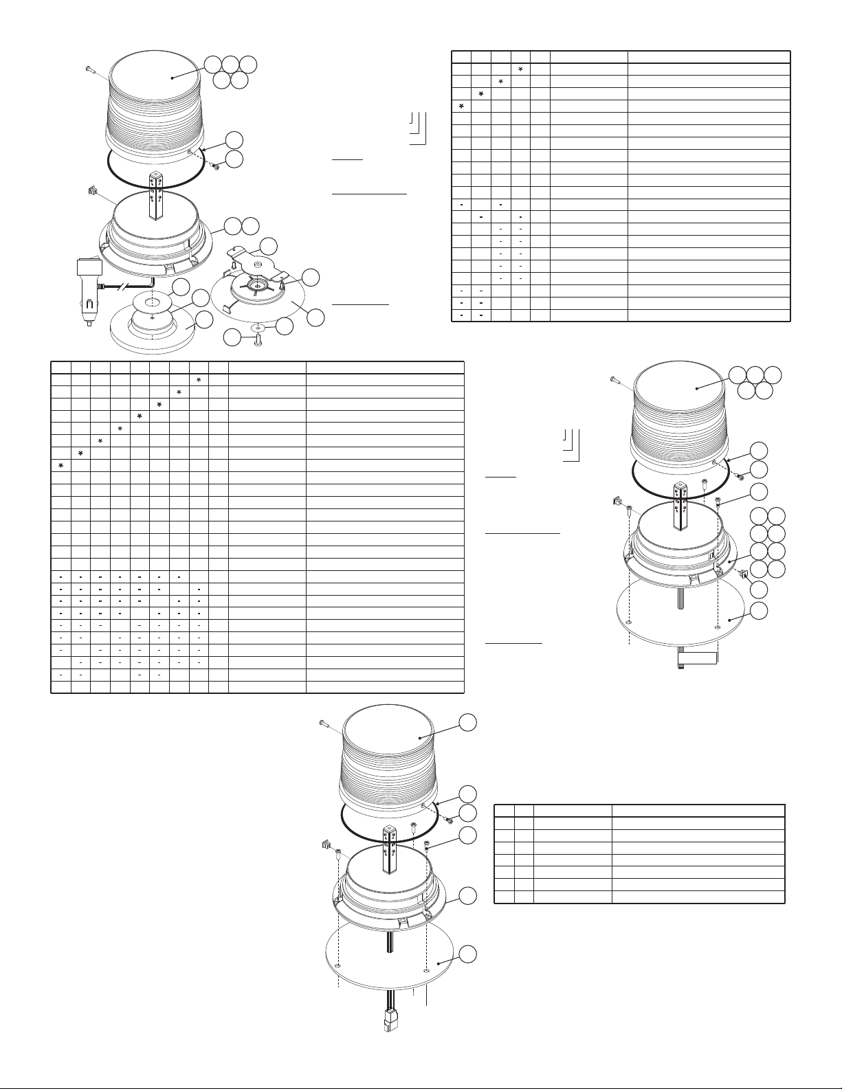
L22E LED BEACON 12V PLASTIC VAC MT. PHOTOCELL
//
L22E LED BEACON 12V PLASTIC VAC MT.
/
L22E LED BEACON 12V PLASTIC MAG MT.
/
L22E LED BEACON 12V PLASTIC MAG MT. PHOTOCELL
//
O RING 4.724 ID X .079 THK 70 DUROMETER BLK
/
SUB ASSY BALLAST L22E 12V PLAS CIG PLUG PHOTO/...//
LENS OPTIC MODEL #1079 RED HI
/
LENS OPTIC MODEL #1079 GREEN HI
/
LENS OPTIC MODEL #1079 BLUE HI
/
LENS OPTIC MODEL #1079 AMBER HI
/
LENS OPTIC MODEL #1079 CLEAR HI
/
LABEL M-N P-N S-N/
TAPE MOUNTING 90LB MAGNET//
LABEL MODEL L22E
/
SCREW #6 X 1/2 PPH PLASTIC-LOC
/
SUB ASSY B ST L22E 12V PLAS CIG PLUGL..
//
MAGNET X-80/
PLATE ADAPTER MAG/SUCTION CUP/
SCREW 8 X 1/2 PPHSMS/
SUCTION CUP MAGNET MOUNT/
WASHER FLAT 1/4" 7/8 OD SS/
SCREW 1/4-20 X 3/4 PPHMS SS/
PAD MOUNTING MAGNETIC MOUNT//
2
3
ITEM PART NUMBER DESCRIPTION
QTY QTY QTY QTY
11
12
13
14
15
16
17
18
19
4
5
6
7
8
9
10
1
7
15
16
17
18
19
01-0686024___
PART NUMBER KEY:
COLOR: HI DOME / LED:
AMB/WHT
BLU/BLU
A=
B=
G=
R=
1=
2=
3=
4=
5=
GRN/GRN
RED/RED
CLR/PC AMB
CLR/BLU
CLR/WHT
CLR/GRN
CLR/RED
HOUSING/MOUNT
1=
4=
PLASTIC MAG. MT
PLASTIC VAC. MT
VOLTAGE
-==12 volt
3 12 volt (Photocell)
Magnet or Vacuum Mount
13
14
12
8
01-0686024___
PART NUMBER KEY:
COLOR: HI DOME / LED:
AMB/WHT
BLU/BLU
A=
B=
G=
R=
1=
2=
3=
4=
5=
GRN/GRN
RED/RED
CLR/PC AMB
CLR/BLU
CLR/WHT
CLR/GRN
CLR/RED
HOUSING/MOUNT
2=
3=
CAST COMBO MT
PLASTIC COMBO MT
VOLTAGE
-=
2=
3=
4=
12 volt
24 volt
12 volt (Photocell)
24Volt (Photocell)
Combo Mount
1
3
21
2
4
5
6
8
9
12
15
17
10
13
16
18
11
14
6
910
415
23
Available Scan-Lock™ Patterns:
# Flash Pattern Phase
1 - SignalAlert™ 75 Phase 1
2 - SignalAlert™ 75 Phase 2
3 - CometFlash® 75 Phase 1
4 - CometFlash® 75 Phase 2
IMPORTANT! It is the responsibility of the installation technician to make sure that the installation and operation of this product will not
interfere with or compromise the operation or efficiency of any vehicle equipment! Before returning the vehicle to active service, visually
confirm the proper operation of this product, as well as all vehicle components/equipment.
5 - DoubleFlash 75 Phase 1
6 - DoubleFlash 75 Phase 2
7 - SingleFlash 75 Phase 1
8 - SingleFlash 75 Phase 2
9 - ComAlert™ 75 Phase 1
10 - ComAlert™ 75 Phase 2
11 - LongBurst™ 75 Phase 1
12 - LongBurst™ 75 Phase 2
13 - PingPong™ 75 Phase 1
14 - PingPong™ 75 Phase 2
15 - SingleFlash 6 0
16 - SingleFlash 9 0
17 - SingleFlash 1 20
18 - SingleFlash 3 00
19 - DoubleFlash 150
20 - ComAlert™ 150
21 - ActionFlash™ 1
22 - ActionFlash™ 2
23 - ModuFlash™
24 - ActionScan™
25 - Steady
Page 3
Page 4
COMBO MOUNT
MAGNET OR VACUUM
MOUNT
VOLTAGE
PART N0. KEY:
01-0686346___
COLOR LO DOME / LED
VOLTAGE
12V
24V
12V (PHOTOCELL)
24V (PHOTOCELL)
-=
2=
3=
4=
COLOR LO DOME / LED
A=
B=
G=
R=
1=
2=
3=
4=
5=
AMBER/AMBER
BLUE/BLUE
GREEN/GREEN
RED/RED
CLEAR/AMBER
CLEAR/BLUE
CLEAR/WHITE
CLEAR/GREEN
CLEAR/RED
HOUSING/MOUNT
2=3=CAST / COMBO MOUNT
PLASTIC / COMBO MOUNT
HOUSING/MOUNT
VOLTAGE
PART N0. KEY:
01-0686346___
COLOR LO DOME / LED
VOLTAGE
12V
12V (PHOTOCELL)
-=
3=
COLOR LO DOME / LED
A=
B=
G=
R=
1=
2=
3=
4=
5=
AMBER/AMBER
BLUE/BLUE
GREEN/GREEN
RED/RED
CLEAR/AMBER
CLEAR/BLUE
CLEAR/WHITE
CLEAR/GREEN
CLEAR/RED
HOUSING/MOUNT
1-4-PLASTIC/MAGNET MOUNT
PLASTIC/VACUUM MOUNT
HOUSING/MOUNT
68-2180452-50
68-2180452-40
68-2180452-30
68-2180452-20
01-06863463_4
01-0686346-_4
07-764648-023
15-081416-080
08-1583927-05
16-1302820-06
14-130216-120
68-2180452-10
66-0421273-00
65-0010192-00
38-0143340-00
38-0443007-00
15-065419-080
01-02863451_1
01-02863451_3
01-0686346-_1
01-06863463_1
A/R
A/R
A/R
A/R
A/R
A/R
A/R
A/R
A/R
A/R
1
1
2
A/RA/R
A/R
A/R A/R
A/R
A/R
A/R
11
A/R
A/R
1
1
22
1
2
1
111
1
1
2
1
1
1
1
121
1
1
1
L22E LED BEACON 12V PLASTIC (VAC MT.) PHOTOCELL
L22E LED BEACON 12V PLASTIC (VAC MT.)
L22E LED BEACON 12V PLASTIC (MAG MT.)
L22E LED BEACON 12V PLASTIC (MAG MT.) PHOTOCELL
O RING, 4.724 ID X .079 THK 70 DUROMETER BLK
SUB ASSY BALLAST, L22E 12V PLASTIC, CIGAR PLUG (PHOTOCELL)
LENS OPTIC, RED LO
LENS OPTIC, GREEN LO
LENS OPTIC, CLEAR LO
LENS OPTIC, BLUE LO
LENS OPTIC, AMBER LO
TAPE, MOUNTING (90LB MAGNET)
SCREW, #6 X 1/2 PPH PLASTIC-LOC
SUB ASSY BALLAST, L22E 12V PLASTIC (CIGAR PLUG)
MAGNET, X-80
PLATE, ADAPTER MAG/SUCTION CUP
SCREW, 8 X 1/2 PPHSMS
SUCTION CUP, MAGNET MOUNT
WASHER, FLAT 1/4" 7/8 OD SS
SCREW, 1/4-20 X 3/4 PPHMS SS
PAD, MOUNTING, MAGNETIC MOUNT
ITEM PART NUMBER DESCRIPTION
QTY QTY QTY QTY
2
3
11
12
13
14
15
16
17
4
5
6
7
8
9
10
1
68-2180452-50
68-2180452-40
68-2180452-30
68-2180452-20
01-06863463_2
01-06863464_2
01-06863463_3
01-06863464_3
01-02863452_3
01-02863452_4
01-02863453_3
01-02863453_4
01-02863453_2
01-02863453_1
01-06863462_3
01-0686346-_3
15-065419-080
01-02863452_2
01-02863452_1
01-06863462_2
01-0686346-_2
38-0241596-00
15-101416-100
13-062C40-16J
38-0443007-00
68-2180452-10
A/RA/RA/RA/R A/R A/R A/R
A/R
A/R
A/R
A/R
A/RA/RA/R A/R A/R
A/R
A/R
A/R
111
A/R
A/R
A/RA/R
A/R
A/R
2322
33
11
A/R
A/R
A/R
A/R
A/R
A/R
232
3
A/R A/R
111
A/R
A/R
A/R A/R
A/R
A/R
22
3323
1
1
1
1
1
121121 1
1
1
1
2
1 121
A/R
L22E LED BEACON (COMBO) 12V PLASTIC
L22E LED BEACON (COMBO) 24V CAST
L22E LED BEACON (COMBO) 12V CAST
L22E LED BEACON (COMBO) 24V PLASTIC (PHOTOCELL)
L22E LED BEACON (COMBO) 12V CAST (PHOTOCELL)
L22E LED BEACON (COMBO) 24V CAST (PHOTOCELL)
L22E LED BEACON (COMBO) 12V PLASTIC (PHOTOCELL)
L22E LED BEACON (COMBO) 24V PLASTIC
O RING
SCREW, 10 X 5/8 PPHSMS 410 SS
LENS OPTIC, GREEN LO
LENS OPTIC, CLEAR LO
LENS OPTIC, BLUE LO
SCREW, #6 X 1/2 PPH PLASTIC-LOC
LENS OPTIC, AMBER LO
LENS OPTIC, RED LO
SUB ASSY BALLAST, L22E 12V CAST (PHOTOCELL)
SUB ASSY BALLAST, L22E 24V CAST (PHOTOCELL)
SUB ASSY BALLAST, L22E 12V PLASTIC (PHOTOCELL)
SUB ASSY BALLAST, L22E 24V PLASTIC (PHOTOCELL)
SUB ASSY BALLAST, L22E 24V PLASTIC
SUB ASSY BALLAST, L22E 12V PLASTIC
SUB ASSY BALLAST, L22E 24V CAST
SUB ASSY BALLAST, L22E 12V CAST
SEAL, BASE MODEL 2000 SERIES B
SCREW, GROMMET #6 #8 FASTEX
2
3
11
12
13
14
15
16
17
18
4
5
6
7
8
9
10
1
ITEM PART NUMBER DESCRIPTION
QTY QTY QTY QTYQTY QTY QTY QTY
01-0286345311
38-0241596-00
15-065419-080
15-101416-100
38-0443007-00
68-2180452-10
01-0686684-A0
1
1
1
1
2
3
L22E LED BEACON (GRADALL)
LENS
SUB-ASS'Y BALLAST, L22E 12V PLASTIC
SEAL, BASE MODEL 2000 SERIES B
SCREW, #6 X 1/2 PPH PLASTI-LOC
O RING
SCREW, #10 - 5/8 PPHSMS
ITEM PART NUMBER DESCRIPTION
QTY
2
3
4
5
6
1
1
2
3
4
5
6
9
10
11 12
13
17
14
15 16
6
7
8
18
123
45
123
45
8
9
11
14
12
13
10
17
16
15
6
7
Page 4
 Loading...