

Page 1

®
ENGINEERING COMPANY INC.
51 Winthrop Road
Chester, Connecticut 06412-0684
Phone: (860) 526-9504
Fax: (860) 526-4078
Internet: www.whelen.com
Sales e-mail: autosale@whelen.com
Canadian Sales e-mail: canadiansales@whelen.com
Customer Service e-mail: custserv@whelen.com
Installation Guide:
Duo WC Inner Edge® XLP
Interior Lightbar
6- and 12-Light Models
2013 Ford Fusion
Whelen’s emergency vehicle warning devices must be properly mounted and wired in order to be effective and safe. Read and follow all of Whelen’s
written instructions when installing or using this device. Emergency vehicles are often operated under high speed stressful conditions which must be
accounted for when installing all emergency warning devices. Controls should be placed within convenient reach of the operator so that he can operate
the system without taking his eyes off the roadway. Emergency warning devices can require high electrical voltages and/or currents. Properly protect and
use caution around live electrical connections.Grounding or shorting of electrical connections can cause high current arcing, which can cause personal
injury and/or vehicle damage, including fire. Many electronic devices used in emergency vehicles can create or be affected by electromagnetic
interference. Therefore, after installation of any electronic device it is necessary to test all electronic equipment simultaneously to insure that they operate
free of interference from other components within the vehicle. Never power emergency warning equipment from the same circuit or share the same
grounding circuit with radio communication equipment. All devices should be mounted in accordance with the manufacturer’s instructions and securely
fastened to vehicle elements of sufficient strength to withstand the forces applied to the device. Driver and/or passenger air bags (SRS) will affect the way
equipment should be mounted. This device should be mounted by permanent installation and within the zones specified by the vehicle manufacturer, if
any. Any device mounted in the deployment area of an air bag will damage or reduce the effectiveness of the air bag and may damage or dislodge the
device. Installer must be sure that this device, its mounting hardware and electrical supply wiring does not interfere with the air bag or the SRS wiring or
sensors. Mounting the unit inside the vehicle by a method other than permanent installation is not recommended as unit may become dislodged during
swerving; sudden braking or collision. Failure to follow instructions can result in personal injury. Whelen assumes no liability for any loss resulting from the
use of this warning device. PROPER INSTALLATION COMBINED WITH OPERATOR TRAINING IN THE PROPER USE OF EMERGENCY WARNING
DEVICES IS ESSENTIAL TO INSURE THE SAFETY OF EMERGENCY PERSONNEL AND THE PUBLIC.
Warnings to Users
Warnings to Installers
Whelen’s emergency vehicle warning devices are intended to alert other operators and pedestrians to the presence and operation of emergency vehicles
and personnel. However, the use of this or any other Whelen emergency warning device does not guarantee that you will have the right-of-way or that
other drivers and pedestrians will properly heed an emergency warning signal. Never assume you have the right-of-way. It is your responsibility to proceed
safely before entering an intersection, driving against traffic, responding at a high rate of speed, or walking on or around traffic lanes. Emergency vehicle
warning devices should be tested on a daily basis to ensure that they operate properly. When in actual use, the operator must ensure that both visual and
audible warnings are not blocked by vehicle components (i.e.: open trunks or compartment doors), people, vehicles, or other obstructions. It is the user’s
responsibility to understand and obey all laws regarding emergency warning devices. The user should be familiar with all applicable laws and regulations
prior to the use of any emergency vehicle warning device. Whelen’s audible warning devices are designed to project sound in a forward direction away
from the vehicle occupants. However, because sustained periodic exposure to loud sounds can cause hearing loss, all audible warning devices should be
installed and operated in accordance with the standards established by the National Fire Protection Association.
Safety First
This document provides all the necessary information to allow your Whelen product to be properly and safely installed. Before beginning the installation
and/or operation of your new product, the installation technician and operator must read this manual completely. Important information is contained herein
that could prevent serious injury or damage.
• Proper installation of this product requires the installer to have a good understanding of automotive electronics, systems and procedures.
• Whelen Engineering recommends the use of waterproof butt splices and/or connectors if that connector could be exposed to moisture.
• Failure to use specified installation parts and/or hardware will void the product warranty.
• If mounting this product requires drilling holes, the installer MUST be sure that no vehicle components or other vital parts could be damaged
by the drilling process. Check both sides of the mounting surface before drilling begins. Also de-burr the holes and remove any metal shards
or remnants. Install grommets into all wire passage holes.
• If this manual states that this product may be mounted with suction cups, magnets, tape or Velcro®, clean the mounting surface with a 50/50
mix of isopropyl alcohol and water and dry thoroughly.
• Do not install this product or route any wires in the deployment area of your air bag. Equipment mounted or located in the air bag deployment
area will damage or reduce the effectiveness of the air bag, or become a projectile that could cause serious personal injury or death. Refer to
your vehicle owner’s manual for the air bag deployment area. The User/Installer assumes full responsibility to determine proper mounting
location, based on providing ultimate safety to all passengers inside the vehicle.
• For this product to operate at optimum efficiency, a good electrical connection to chassis ground must be made. The recommended
procedure requires the product ground wire to be connected directly to the NEGATIVE (-) battery post (this does not include products that use
cigar power cords).
• If this product uses a remote device for activation or control, make sure that this device is located in an area that allows both the vehicle and
the device to be operated safely in any driving condition.
• Do not attempt to activate or control this device in a hazardous driving situation.
• This product contains either strobe light(s), halogen light(s), high-intensity LEDs or a combination of these lights. Do not stare directly into
these lights. Momentary blindness and/or eye damage could result.
• Use only soap and water to clean the outer lens. Use of other chemicals could result in premature lens cracking (crazing) and discoloration.
Lenses in this condition have significantly reduced effectiveness and should be replaced immediately. Inspect and operate this product
regularly to confirm its proper operation and mounting condition. Do not use a pressure washer to clean this product.
• It is recommended that these instructions be stored in a safe place and referred to when performing maintenance and/or reinstallation of this
product.
• FAILURE TO FOLLOW THESE SAFETY PRECAUTIONS AND INSTRUCTIONS COULD RESULT IN DAMAGE TO THE PRODUCT OR VEHICLE
Automotive: Lightbars
AND/OR SERIOUS INJURY TO YOU AND YOUR PASSENGERS!
©2013 Whelen Engineering Company Inc.
Form No.14725 (090313)
For warranty information regarding this product, visit www.whelen.com/warranty
Page 1
Page 2
DRIVER SIDE DOOR
Pry plastic
cover off
VISOR SWIVEL
BRACKET
WINDSHIELD
Remove screw
and visor clip
VISOR
CLIP
MOUNTING CLIP
(remove)
V
I
S
O
R
Fig. 1
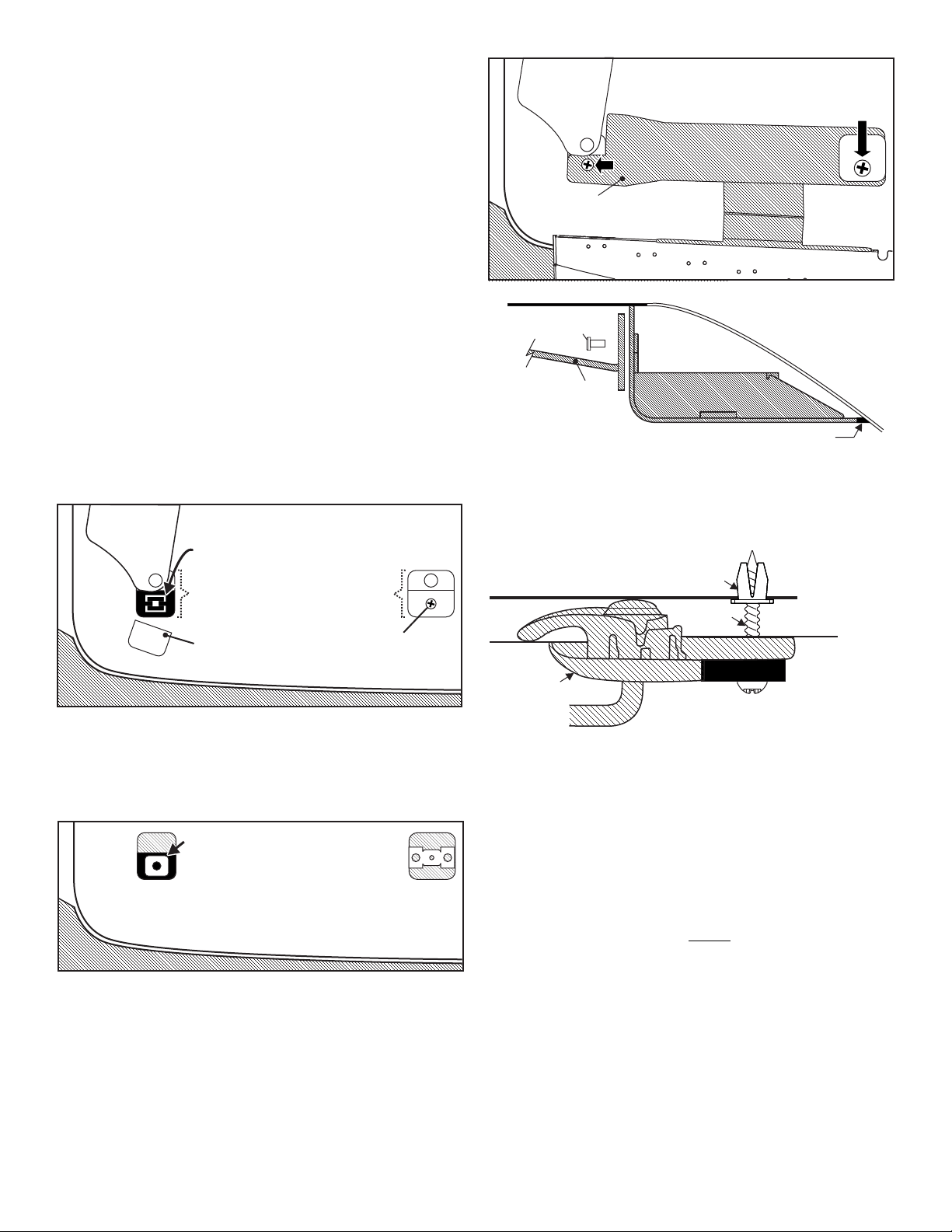
WINDSHIELD
Installation 2013 Ford Fusion:
Install Faston grommet
into existing hole in roof
that clip snapped into.
Fig. 2
Fig. 4
When properly mounted, the rubber seal should be in full
contact with the vehicle windshield. The rear of the lightbar
should be in contact with the roof. This is to prevent light
from entering the passenger compartment. When this has
been achieved, tighten mounting hardware firmly to
maintain contact.
Mounting
Bracket
ROOF
#8-32 x 3/8 Torx Hd
Screw (QTY 2)
W
I
N
D
S
H
I
E
L
D
RUBBER SEAL
Lightbar
Side View
Lightbar
Side View
Lightbar
Side View
Fig. 5
ROOF SHEET METAL
SCREW
GROMMET
HEADLINER
VISOR
SWIVEL
BRACKET
LT BAR BRACKET
MOUNTING TAB
Re-install visor clip over bracket
using supplied #8 X 1" sheet metal screw
Install into Faston grommet using
supplied 1/4 X 1-1/4" PPHSMS
Install into Faston grommet using
supplied 1/4 X 1-1/4" PPHSMS
Install into Faston grommet using
supplied 1/4 X 1-1/4" PPHSMS
MOUNTING
BRACKET
Fig. 3
IMPORTANT AIR BAG WARNING! Do not install this product or route
any wires in the deployment area of your air bag. Equipment
mounted or located in the air bag deployment area will damage or
reduce the effectiveness of the air bag, or become a projectile that
could cause serious personal injury or death. Refer to your vehicle
owners manual for the air bag deployment area. The User/ Installer
assumes full responsibility to determine proper mounting location,
based on providing ultimate safety to all passengers.
IMPORTANT! The lightbar should be located a minimum of 16" from
any radio antennas!
Note: When routing the wires, it is important to choose a path that
will keep the wires away from excessive heat or any vehicle
equipment that could compromise the integrity of the wires (ex.
trunk lids, door jams, etc.)
Figures 1 thru 3 show the driver side of the interior of the vehicle, shown
looking up at the roof.
1. On the driver side visor swivel bracket, carefully pry the plastic cover
off of the front of the bracket (Fig. 1). The lightbar mounting bracket
will sit in the space that the cover occupied. NOTE: Pry the cover
off using two flat blade screwdrivers on each side to avoid
braking the cover. The cover will not be used here but should be
saved in case you wish to remove the lightbar in the future.
2. Remove the swivel bracket mounting clip (located under the cover
you removed in step 1) and lift the swivel bracket assembly out.
Install the supplied fastex grommet into the hole in the roof sheet
metal which the clip snapped into. Reinsert the swivel bracket
assembly (Figs. 1 & 2).
3. On the vehicle visor clip, remove the screw holding on the clip and
remove the clip. The supplied #8 X 1" sheet metal screw will replace
the screw you removed (Fig. 2).
4. Secure the mounting bracket to the lightbar and position the bracket
where it will mount on the vehicle (Figs. 3 & 4).
5. Secure the lightbar bracket to the swivel mount using the supplied 1/
4 X 1-1/4” Phillips Pan Head Sheet Metal Screw. This screw will
thread into the fastex grommet you installed in step 2 and the bracket
will sit where the cover was (Fig. 5).
6. Line the rectangular hole in the other end of the lightbar bracket, up
with the visor clip and install the visor clip over the lightbar bracket
using the supplied #8 X 1” Sheet Metal Screw (Fig. 3).
7. Make sure all mounting hardware is tightened firmly and repeat
procedure for the passenger side of the vehicle.
8. Extend the cables and connect to power. Refer to the lightbar manual
for wiring and fusing information.
Connecting the Power Cable:
WARNING! All customer supplied wires that connect to the positive
terminal of the battery must be sized to supply at least 125% of the
maximum operating current and FUSED
load. DO NOT USE CIRCUIT BREAKERS WITH THIS PRODUCT!
1. Follow the factory wiring harness through the firewall. It may be
necessary to drill a hole in the firewall. If so, be absolutely sure that
there are no components that could be damaged by drilling. After the
hole has been drilled, insert a grommet to protect the cable.
2. Route the cable along the factory wiring harness towards the battery.
Install a 40 amp fuse block (customer supplied) on the end of the
RED wire in the power cable. NOTE: Remove the fuse from the
fuse block before connecting any wires to the battery.
3. Connect the BLACK wire to Chassis Ground.
Page 2
at the battery to carry that
Page 3

Connecting the Communication Cable:
CAUTION! DO NOT LOOK DIRECTLY AT THESE LED’S WHILE THEY ARE ON.
MOMENTARY BLINDNESS AND/OR EYE DAMAGE COULD RESULT!
IMPORTANT WARNING!
COLOR
GREEN
GRN/WHT
GRN/BLK
WHT/RED
WHITE
YELLOW
WHT/VIO
WHT/GRN
WHT/ORG
BLUE
BLU/WHT
BLU/BLK
WHT/BRN
WHT/BLK
WHT/BLU
RED/WHT
WHT/YEL
VIOLET
*
*
ALTERNATING DRIVER-PASSENGER (SignalAlert™ 75)
DRIVER OUTBOARD DUO (STEADY)
PASSENGER OUTBOARD DUO (STEADY)
DRIVER INBOARD (CA STEADY)
OUTBOARD DUO (SingleFlash 150)
CRUISE LIGHTS
CA BAR PATTERN
ULTRA SCAN BAR PATTERN
CA SINGLE
ZZ CA 75 BAR PATTERN
CENTER DUO (STEADY)
ALTERNATING SIDE-TO-SIDE DUO (DoubleFlash 75)
LOW POWER
ALTERNATING SIDE-TO-SIDE (SignalAlert™ 75)
IN-OUT (SignalAlert™ 75)
ALTERNATING DRIVER-PASSENGER (ASYNC) (SignalAlert™ 75)
ULTRA SCAN BAR PATTERN
ALL DUO (STEADY)
CENTER DUO (SingleFlash 150)
FUNCTIONPOS
1
2
3
4
5
6
7
8
9
10
11
12
13
14
15
16
17
18
Connect to an ignition controlled
circuit that can accommodate an
additional 250mA load.
from lightbar
1
2
USB
Port
18 9
17
8
16
7
15
6
14
5
13
4
12
3
11
2
10
1
142
5
3
6
Lightbar
Cable
Connector
2
1
2
2
COLOR
RED
None
BLACK
GREEN
BLK/WHT
GREY
FUNCTION
+12VDC
GROUND
COMM. A
SHIELD
COMM. B
POS
1
2
3
4
5
6
DEFAULT CONFIGURATION
(
12V Inputs
)
1
1
8
14-08228C-06D
SCREW, 8-32 X 3/8" PAN TORX HD ROLOK SS BLK OXIDE
1
39-1M18534-05
HSNG, PLUG 5 POS 18 AWG SL-156 W/ LOCKING RAMP, LID
1
46-0746909-00
ASS'Y, CABLE 4/C 16/20 GA TPR 20' SL-156
1
26-0215001-06
TY WRAP, 6" BLACK
1
01-026E763-00
SUB ASSY, WC I/O INNER-EDGE DUO XLP
1
46-076E764-00
ASSY, HARNESS PASSENGER J8 INNER EDGE XLP
1
46-076E764-01
ASSY, HARNESS PASSENGER J7 INNER EDGE XLP
01-026E756D*3
SUB ASSY, WARNING */WHT DUO INNER-EDGE XLP, DRVR
01-026E756P*3
SUB ASSY, WARNING */WHT DUO INNER-EDGE XLP, PASS
4
1
1
1
1
1
1
01-0687472-_1
DUO INNER EDGE XLP, WC 6 LT
2
38-0546827-14
TRIM, SEAL HSNG/WINDSHIELD 13.600" LENGTH INNER EDGE XLP
1
1
10-056E563-30
1
LABEL, WHELEN LOGO, 2.75" GREY
01-0687472-_2
DUO INNER EDGE XLP, WC 12 LT
LABEL, INNER EDGE XLP, M/N P/N DUO
10-056E831-**
11
SCREW, 4-40 X 1/4 PPHMS 410SS BLACK PASSIVATE
14-040216-04H
26
14
ASSY, HARNESS DRIVER J5&J6 INNER EDGE XLP
46-076E764-02
1
66
6
10-0546935-18
79-000A005-00
01-046E868-00
11
11
11
DEFAULT, DUO INNER EDGE XLP WECAN
LABEL, UCP, DFLT, DUO INNER EDGE XLP
KIT, UNIVERSAL CONTROL POINT MODULE
2
3
ITEM
PART NUMBER
DESCRIPTION
QTY QTY
11
12
13
14
15
16
17
4
5
6
7
8
9
10
1
10
01-0687472-C1
01-0687472-C2
21-12081205-3
SCREW GROMMET, FASTEX # 212-240602-040101
DUO INNER EDGE XLP, 6 LIGHT
DUO INNER EDGE XLP, 12 LIGHT
11-26E925-107
11-26E925-007
07-287529-123
07-287529-023
11-36E891-007
11-36E891-107
BASE, HOUSING DRVR 2013 FUSION INNER EDGE XLP BLACK
COVER, TOP DRVR FORD FUSION DUO INNER EDGE XLP BLACK
COVER, TOP PASS FORD FUSION DUO INNER EDGE XLP BLACK
BASE, HOUSING PASS 2013 FUSION INNER EDGE XLP BLACK
BRACKET, VISOR MT DRVR FUSION INNER EDGE XLP BLACK
BRACKET, VISOR MT PASS FUSION INNER EDGE XLP BLACK
1
-
1
11
1
1
1
11
12
21
15-131416-202
SCREW, 1/4 X 1 1/4 PPHSMS SS TYPE A
241
2
15-081416-160
14-08228C-06D
SCREW, 8 X 1 PPHSMS
SCREW, 8-32 X 3/8" PAN TORX HD ROLOK SS BLK OXIDE
B
C
ITEM
PART NUMBER
DESCRIPTION
QTY QTY
D
E
F
G
H
I
J
A
2013 - FORD FUSION
PART NUMBER KEY
01-0687472- C _
VERSION
6 LT
12 LT
1 =
2 =
2
6
13 14
Splice the GREEN and GREY wires from the lightbar to the GREEN and
GREY wires from the Whelen WC Controller.
Control Point Module:
The Control Point Module serves as the ‘brains’ of the Whelen WC Series
lightbar. The module is programmed with the WeCan™ Programming
Software via the USB port and in turn, provides the necessary signals that
allow the lightbar to function in the desired manner.
Page 3
Each of the 18 inputs in WeCan™ Programming software may be
programmed to activate any number or combination of installed lightbar
components by applying +12VDC to an input. Refer to the installation
guide included with your switches for detailed wiring information.
Programming Procedure:
IMPORTANT - It is not necessary to program this device unless
changes to the default configuration (for example pattern or switch
control changes) are desired.
1. Connect a USB cable from the host PC to the module’s USB port.
2. Start the WeCan software on the host PC and open the configuration
to be programmed.
3. Click on the WeCan button on the menu bar. Select “Control Point”
then “Program” from the fly-out.
4. A window will open to confirm that you are about to program a
Control Point Module. Confirm that the USB cable is connected to
both the module and the PC and then press “OK” to continue. The
software will display a window when the programming procedure has
been successfully completed.
5. Confirm proper operation of the module.
Troubleshooting:
Your lightbar should now be fully operational. If it is not functioning
properly, check your connections for the following:
• The positive wire (RED) is properly connected to the battery, by
way of the user supplied fuse block.
• A working fuse of the correct amperage is installed in the fuse
block (See illustration above, for the specific fuse rating for
your lightbar).
• The ground wire (BLACK) is properly connected to the factory
ground. Be sure that the wire is fully grounded to this location.
• The two communication wires (GREEN and GREY) are properly
connected to their communication designations.
If these connections are good, contact your Whelen® representative for
further assistance.
IMPORTANT! Before returning this vehicle to active service, visually
confirm the proper operation of this product, as well as all vehicle
components/equipment.
 Loading...