

Page 1

®
ENGINEERING COMPANY INC.
51 Winthrop Road
Chester, Connecticut 06412-0684
Phone: (860) 526-9504
Fax: (860) 526-4078
Internet: www.whelen.com
Sales e-mail: [email protected]
Canadian Sales e-mail: [email protected]
Customer Service e-mail: [email protected]
Intelligent Strobe Power Supply
Installation Guide:
Model ISP188
Safety First
This document provides all the necessary information to allow your Whelen product to be properly and safely installed.
Before beginning the installation and/or operation of your new product, the installation technician and operator must
read this manual completely. Important information is contained herein that could prevent serious injury or damage.
• Proper installation of this product requires the installer to have a good understanding of automotive
electronics, systems and procedures.
• If mounting this product requires drilling holes, the installer MUST be sure that no vehicle components or
other vital parts could be damaged by the drilling process. Check both sides of the mounting surface
before drilling begins. Also de-burr any holes and remove any metal shards or remnants. Install grommets
into all wire passage holes.
• If this manual states that this product may be mounted with suction cups, magnets, tape or Velcro®, clean
the mounting surface with a 50/50 mix of isopropyl alcohol and water and dry thoroughly.
• Do not install this product or route any wires in the deployment area of your air bag. Equipment mounted
or located in the air bag deployment area will damage or reduce the effectiveness of the air bag, or
become a projectile that could cause serious personal injury or death. Refer to your vehicle owner’s
manual for the air bag deployment area. The User/Installer assumes full responsibility to determine proper
mounting location, based on providing ultimate safety to all passengers inside the vehicle.
• For this product to operate at optimum efficiency, a good electrical connection to chassis ground must be
made. The recommended procedure requires the product ground wire to be connected directly to the
NEGATIVE (-) battery post.
• If this product uses a remote device to activate or control this product, make sure that this control is
located in an area that allows both the vehicle and the control to be operated safely in any driving
condition.
• Do not attempt to activate or control this device in a hazardous driving situation.
• It is recommended that these instructions be stored in a safe place and referred to when performing
maintenance and/or reinstallation of this product.
• FAILURE TO FOLLOW THESE SAFETY PRECAUTIONS AND INSTRUCTIONS COULD RESULT IN DAMAGE
TO THE PRODUCT OR VEHICLE AND/OR SERIOUS INJURY TO YOU AND YOUR PASSENGERS!
Automotive: Power Supplies
For warranty information regarding this product, visit www.whelen.com/warranty
©1998 Whelen Engineering Company Inc.
Form No.13306B (072507)
Page 1
Page 2

Selecting a Mounting Location . . .
The logical choice for a mounting area would be a trunk or similar compartment.
However, due to the wide variety of vehicles onto which the ISP188 can be installed,
this is not always possible. The following guidelines will help the installer select an
acceptable alternative:
A) The unit should be mounted on a metal surface to aid heat dissipation. Be sure
that this surface is not one that either generates or is exposed to excessive
heat during normal operation of the vehicle.
B) Do not select a location where the power supply will be exposed to potential
damage from any unsecured or loose equipment in the vehicle.
C) Be sure the area selected will not allow the ISP188 to be exposed to water!
D) When routing the wires, it is important to choose a path that will keep these
wires away from excessive heat and from any vehicle equipment that could
compromise the integrity of the wires (ex. trunk lids, door jams, etc.).
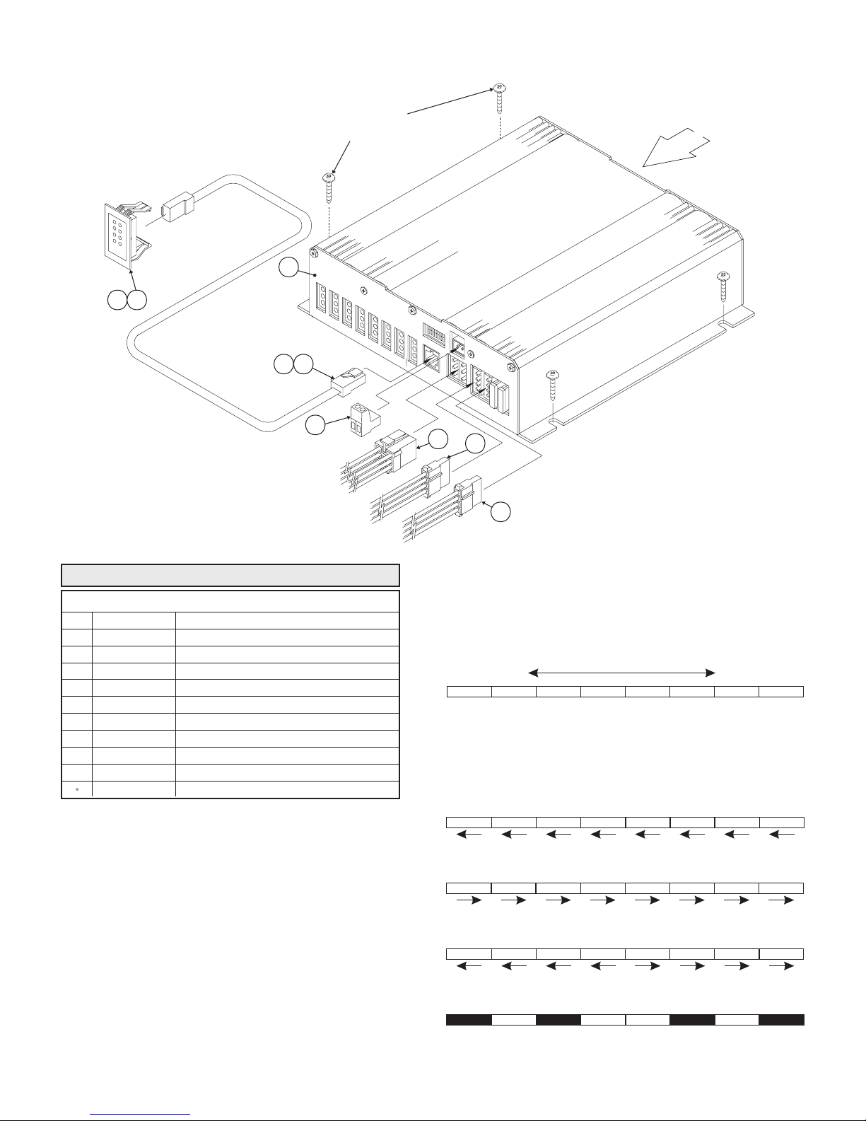
E) Be sure your mounting location does not block the cooling fan in the rear of the
unit. (See last page)
WARNING: All customer supplied wires that connect to the positive terminal of
the battery must be sized to supply at least 125% of the maximum operating
current and FUSED
BREAKERS WITH THIS PRODUCT!
WARNING: When extending the communication wires (BLUE & GREY), use
either the Whelen 25ft cable (P/N 46-9641638-250) or similar “twisted pair”
wires!
CAUTION: Permanent mounting of this product will require drilling. It is
absolutely necessary to make sure that no other vehicle components could be
damaged by this process. Check both sides of the mounting surface before
starting. If damage is likely, select a different mounting location.
at the battery to carry that load. DO NOT USE CIRCUIT
Operating Instructions . . .
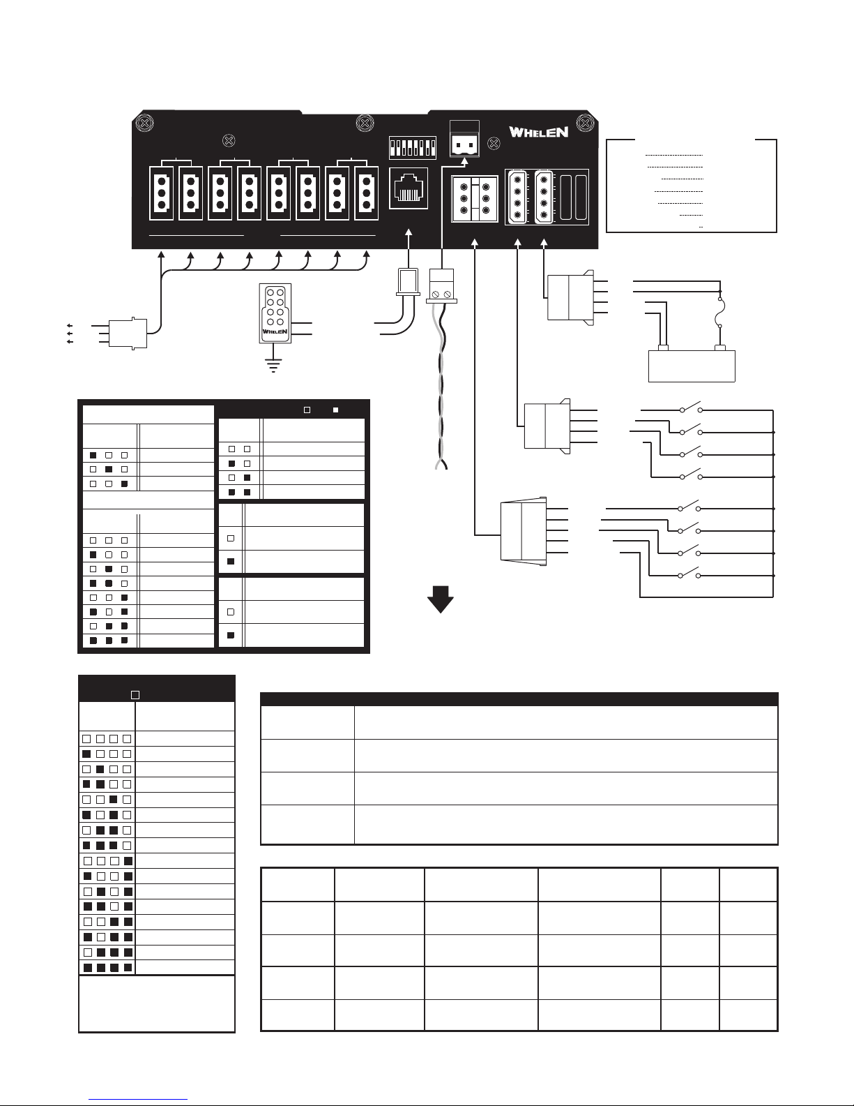
The ISP188 has been designed to emulate the operations of four existing Whelen
power supplies:
The UPS-188C (Alternating Pairs) - ALT 2X2X4
The DOT-188C (Simultaneous Pairs) - SIMUL. 2X2X4
The DOT-188MN (Simultaneous) - SIMUL. 2X2X4
The BL188C - B-LINK
Selecting the desired operational mode is accomplished by configuring dip switches
#1, #2 #3 & #8, located on the front panel of the power supply. The use of Dip
Switches #4 & #5 is explained in the “Hil/Low Power” section. The following section
will explain how to place the ISP188 into each of these respective modes, as well as
outline the operational procedures for each mode.
Section 1: Emulation Modes . . .
Applying +12VDC to the control wires indicated in each mode (using customer
supplied switches) will cause the results indicated. For a listing of the available flash
patterns refer to Section 2: Flash Patterns.
ALT. 2X2X4 Mode (Default Configuration) . . .
Dip Switches
The dip switch configuration for UPS188C-mode is:
Dip Switch 1 - OFF Dip Switch 3 - OFF
Dip Switch 2 - OFF Dip Switch 8 - OFF
Control Wires
Control Wire #1 = Outlets 1 & 2 Enabled
Control Wire #2 = Outlets 3 & 4 Enabled
Control Wire #3 = 5, 6, 7 & 8 Enabled
SIM 2X2X4 Mode . . .
Dip Switches
The dip switch configuration for DOT-188C mode is:
Dip Switch 1 - ON Dip Switch 3 - OFF
Dip Switch 2 - OFF Dip Switch 8 - OFF
Control Wires
Control Wire #1 = Outlets 1 & 3 Enabled
Control Wire #2 = Outlets 5 & 7 Enabled
Control Wire #3 = 2, 4, 6 & 8 Enabled
SIM 2X2X4MN Mode . . .
Dip Switches
The dip switch configuration for DOT188MN Mode:
Dip Switch 1 - OFF Dip Switch 3 - OFF
Dip Switch 2 - ON Dip Switch 8 - OFF
Control Wires
Control Wire #1 = Outlets 2 & 4 Enabled
Control Wire #2 = Outlets 6 & 8 Enabled
Control Wire #3 = Outlets 1, 3, 5 & 7 Enabled
ALT 2X2X2X2 Mode . . .
Dip Switches
The dip switch configuration for ALT 2X2X2X2 Mode:
Dip Switch 1 - ON Dip Switch 3 - OFF
Dip Switch 2 - ON Dip Switch 8 - OFF
Control Wires
Control Wire #1 = Outlets 1 & 2 Enabled
Control Wire #2 = Outlets 3 & 4 Enabled
Control Wire #3 = Outlets 5 & 6 Enabled
Control Wire #4 = Outlets 7 & 8 Enabled
NOTE: If Hi/Lo is to be used turn on dip switch 6 and use the pattern 4 control wire.
SIM 2X2X2X2 Mode . . .
Dip Switches
The dip switch configuration for SIM 2X2X2X2 Mode:
Dip Switch 1 - OFF Dip Switch 3 - ON
Dip Switch 2 - OFF Dip Switch 8 - OFF
Control Wires
Control Wire #1 = Outlets 1 & 3 Enabled
Control Wire #2 = Outlets 2 & 4 Enabled
Control Wire #3 = Outlets 5 & 7 Enabled
Control Wire #4 = Outlets 6 & 8 Enabled
NOTE: If Hi/Low is to be used turn on dip switch 6 and use the pattern 4 control wire.
BL188C Mode . . .
When the ISP188 is configured to emulate the BL188C, it is important to understand
that the connections and operational procedures used are quite different from any of
the other modes.
Dip Switches
BL188C emulation is accomplished by placing Dip Switch 8 in the ON position. At this
point, the remaining Dip Switches (1 thru 3) are used to configure the address of the
ISP188 for use in a B-LINK system. The addressing properties function as follows:
To Configure Address 1 To Configure Address 2
Dip Switch 1 - ON Dip Switch 1 - OFF
Dip Switch 2 - OFF Dip Switch 2 - ON
Dip Switch 3 - OFF Dip Switch 3 - OFF
To Configure Address 3
Dip Switch 1 - OFF
Dip Switch 2 - OFF
Dip Switch 3 - ON
Control Wires
In this configuration, control wires 1, 2, 3 & 4 are not used to enable outlets or control
Hi/Low power activation, as with the previous modes. Outlet control and Hi/Low
power activation is handled by the B-LINK Multi-Purpose Controller.
Section 2: Flash Patterns
The ISP188 can generate any of 16 available flash patterns simply activating the 4
Pattern Control wires, either individually or in combination. Table 1 on Page 3 outlines
all of the available patterns and the wire activations needed to produce them.
Section 3: Hi/Low Power
Hi/Low power activation and functionality can be configured in any of 4 available
modes, depending upon how Dip Switches 4 & 5 are positioned. Table 2 on Page 3
outlines each of the 4 configurations and their attributes.
NOTE: In BL188C emulation mode, Hi/Low power activation is controlled with the BLINK Multi-Purpose Controller.
Section 4: Diagnostix™ (Optional)
The optional Diagnostix display allows the operator to confirm proper operation of not
only the 8 outlets on the ISP188, but of the strobe light and strobe cable connected to
these outlets as well. Each LED indicator on the Diagnostix display, provides
diagnostic information for one outlet. For example; LED #1 monitors Outlet #1, etc.
The LEDs appearance indicates the condition of it’s corresponding outlet. Refer to
Table 3 on Page 3.
Section 5: Phasing
When you turn dip switch 7 on, you will cause outlets 1-4 to drift slowly in and out of
sync with outlets 5-8. Lights will work as described in each mode. The result will be a
more eye catching or random flash pattern.
Page 2
Page 3
12
ISP188
WIRING DIAGRAM
PATTERN
COMM
CTRL
POWER
FUSE
V-INPUT
I-IN 12.8V
FLASHRATE
JOULES HI
JOULES LO
OUTPUT POWER
OUTPUT PER OUTLET
15A15A
UNIT SPECIFICATIONS
12.8VDC ±20%
18 AMPS (TYP)
150 FPM (MIN)
8/3.5/3.5/3.5 (TYP)
2/2/2/2 (MIN)
180 WATTS
22.5 WATTS (TYP)
DIP SWITCHES
ALTERNATINGALTERNATINGALTERNATINGALTERNATING
DIAGNOSTIC
4
OUTLETS
5
3
6
78
INDICATOR
TO DESIRED
LIGHTHEAD
ASSEMBLY.
(TYP. 8 PLACES)
RED
BLACK
WHITE
SWITCH 8 ON,
B-LINK CONTROL
SWITCH
1
SWITCH
1
PATTERN
WIRE
Pattern Wire 1 = BROWN
Pattern Wire2=WHITE
Pattern Wire3=GREY
Pattern Wire4=ORANGE
POWER SUPPLY
23
SWITCH 8 OFF,
PARALLEL CONTROL.
32
ALT. 2X2X4
SIM. 2X2X4
SIM. 2X2X4MN
ALT 2X2X2X2
SIM. 2X2X2X2
TRAFFIC ADVISOR™
FLASH PATTERNS:
= +12VDC
PATTERN TYPE
4321
CometFlash®
TripleFlash™
DoubleFlash
Rapid Random
Sequential
ModuFlash™
MicroBurst II™
MicroBurst III™
2X CometFlash®
2X TripleFlash™
2X DoubleFlash
1/2 Rapid Random
2X Sequential
2X ModuFlash™
2X MicroBurst II™
2X MicroBurst III™
ADDRESS
1
2
3
SYSTEM
TYPE
FUTURE
FUTURE
Diagnostix
BLACK
GROUND
DIP SWITCHES
SWITCH
4
SW
6
SW
7
Hi/Low CONTROL
5
PAT 4 INPUT CONTROL
FOR 2X2X2X2 SWITCHING
SEL PAT 9 - 16
CONTROLS LO POWER
POWER SUPPLY
OUTLET CONTROL
OUTLETS 1-4 IN PHASE
WITH OUTLETS 5-8.
OUTLETS 1-4 NOT IN
PHASE WITH OUTLETS 5-8.
Table 2
IF THE LED IS...
continuously
FLASHING
ON continuously
with a single flash
every few seconds
Table 3
Hi/Lo Mode
Latched
Level
Toggle
DISABLED
LATCH
LEVEL
TOGGLE
DISABLE
OFF
ON
rapidly
Type
TO DIAGNOSTIC
INDICATOR PANEL
=ON =OFF
Recommended
Switch type
Momentary
Single Pole/
Single Throw
Momentary
RED
RED
BLACK
GREY
BLUE
BLACK
YELLOW
GREEN
BLUE
VIOLET
GROUND
12V BATTERY
+12V
CTRL 1
CTRL 2
CTRL 3
CTRL 4
PATTERN 1
PATTERN 2
PATTERN 3
PATTERN 4
BLUE: to RS485A
25 ft. Communication Cable
GREY: to RS485B
(Twisted Pair)
P/N 46-9641638250
BROWN
WHITE
GRAY
ORANGE
WHT/RED
SWITCH BIAS
TO
B-LINK
CONTROL SWITCHES
(SUPPLIED BY CUSTOMER)
THEN...
Either the outlet in question is not enabled, or the power supply is not turned on.
The outlet, strobe cable and strobe light in question are functioning properly.
Either the outlet, strobe cable and/or strobe light in question are malfunctioning.
In this condition, further investigation of the components is strongly recommended
The ISP188 is operating in Lo power mode.
NONE
To Enable
Lo Power Operation
Apply +12VDC to
VIOLET control wire
Apply +12VDC to
VIOLET control wire
Apply +12VDC to
VIOLET control wire
No Low Power
Operation in This Mode
To Restore
Hi Power Operation
Turn all strobe outlets
off and then on.
Remove +12VDC
from VIOLET control wire
Apply +12 VDC to
VIOLET control wire
Not Applicable
Dip Switch
4
OFF
ON
OFF
ON
Dip Switch
30 AMP FUSE
(SUPPLIED BY
CUSTOMER)
5
OFF
OFF
ON
ON
Page 3
Page 4
ISP188 REPLACEMENT PARTS
WHEN MOUNTING UNIT
N0.8 X 5/8 PAN HEAD
SHEET METAL SCREWS
(QUANTITY 4)
W
H
E
L
E
N
D
I
A
G
N
O
S
T
I
X
1
7
2
8
5
KEEP REAR SIDE CLEAR
OF OBSTRUCTIONS.
AIR FLOW
5
ISP188 PARTS LIST
ITEM PART NUMBER DESCRIPTION
25' TWISTED PAIR B-LINK CABLE46-9641638250REF
46-0725612-00 POWER CONNECTOR ASSEMBLY9
02-0241485-25 CABLE ASSY, 8 POS TELEPHONE 25'8
01-0267643-007
DOT DIAGNOSTIC INDICATOR ASSEMBLY
CABLE ASSY, 8 POS TELEPHONE 8’02-0241485-086
2 POS PHOENIX CONNECTOR39CIJ02523-IJ5
4 46-0725945-00 PATTERN CONNECTOR ASSEMBLY
3
01-0267265-00
2
01-0662681-001
CONTROL CONNECTOR ASSEMBLY46-0725613-00
UPS DIAGNOSTIC INDICATOR ASSEMBLY
ISP188 FINAL ASSEMBLY
01-0683125-00 ISP188 STROBE POWER SUPPLY
Traffic Advisor Mode...
Dip Switches
The dip switch configuration for Traffic Advisor Mode:
Dip Switch1-ON
Dip Switch2-ON
Dip Switch3-ON
Control Wires
In this configuration, applying +12VDC to the control
wires (using customer supplied switches) will have
the following results:
Control Wire #1 = LEFT SWEEP
Control Wire #2 = RIGHT SWEEP
Control Wire #3 = ALTERNATING FLASH
Control Wire #2 & #3 = SPLIT SWEEP
4
3
9
TRAFFIC ADVISOR™
In order for the Traffic Advisor patterns to flash properly,
it is necessary for the lamps to be connected to the
ISP188 in the following pattern.
LEFT RIGHT
Lamp 1 Lamp 2 Lamp 3 Lamp 4 Lamp 5 Lamp 6
Outlet1Outlet5Outlet3Outlet7Outlet2Outlet
The Traffic Advisor (or T/A) mode is comprised of four,
traffic control-oriented flash patterns.
76543218
12345678
32112344
21
The T/A pattern mode is enabled as indicated in table 2.
Page 4
LEFT SWEEP
RIGHT SWEEP
SPLIT-SWEEP
ALTERNATING FLASH
Lamp 7 Lamp 8
Outlet4Outlet
6
8
12
 Loading...