

Page 1

®
ENGINEERING COMPANY INC.
51 Winthrop Road
Chester, Connecticut 06412-0684
Phone: (860) 526-9504
Fax: (860) 526-4078
(with Beacons & Power Supply)
Models: G7M*, G7P*, G7M***, G7P***
Installation Guide:
Guardian™ Lightbar
Internet: www.whelen.com
Sales e-mail: autosale@whelen.com
Canadian Sales e-mail: autocan@whelen.com
Customer Service e-mail: custserv@whelen.com
Safety First
This document provides all the necessary information to allow your Whelen product to be properly and safely installed.
Before beginning the installation and/or operation of your new product, the installation technician and operator must
read this manual completely. Important information is contained herein that could prevent serious injury or damage.
• Proper installation of this product requires the installer to have a good understanding of automotive electronics,
systems and procedures.
• If mounting this product requires drilling holes, the installer MUST be sure that no vehicle components or other
vital parts could be damaged by the drilling process. Check both sides of the mounting surface before drilling
begins. Also de-burr any holes and remove any metal shards or remnants. Install grommets into all wire
passage holes.
• If this manual states that this product may be mounted with suction cups, magnets, tape or Velcro®, clean the
mounting surface with a 50/50 mix of isopropyl alcohol and water and dry thoroughly.
• Do not install this product or route any wires in the deployment area of your air bag. Equipment mounted or
located in the air bag deployment area will damage or reduce the effectiveness of the air bag, or become a
projectile that could cause serious personal injury or death. Refer to your vehicle owner’s manual for the air bag
deployment area. The User/Installer assumes full responsibility to determine proper mounting location, based
on providing ultimate safety to all passengers inside the vehicle.
• For this product to operate at optimum efficiency, a good electrical connection to chassis ground must be
made. The recommended procedure requires the product ground wire to be connected directly to the NEGATIVE
(-) battery post.
• If this product uses a remote device to activate or control this product, make sure that this control is located in
an area that allows both the vehicle and the control to be operated safely in any driving condition.
• Do not attempt to activate or control this device in a hazardous driving situation.
• This product contains either strobe light(s), halogen light(s), high-intensity LEDs or a combination of these
lights. Do not stare directly into these lights. Momentary blindness and/or eye damage could result.
• Use only soap and water to clean the outer lens. Use of other chemicals could result in premature lens cracking
(crazing) and discoloration. Lenses in this condition have significantly reduced effectiveness and should be
replaced immediately. Inspect and operate this product regularly to confirm its proper operation and mounting
condition. Do not use a pressure washer to clean this product.
• It is recommended that these instructions be stored in a safe place and referred to when performing
maintenance and/or reinstallation of this product.
• FAILURE TO FOLLOW THESE SAFETY PRECAUTIONS AND INSTRUCTIONS COULD RESULT IN DAMAGE TO
THE PRODUCT OR VEHICLE AND/OR SERIOUS INJURY TO YOU AND YOUR PASSENGERS!
Automotive: Lightbars
For warranty information regarding this product, visit www.whelen.com/warranty
© 2003 Whelen Engineering Company Inc.
Form No.13750C (021407)
Page 1
Page 2
IMPORTANT! The lightbar should be located a minimum of 16"
from any radio antennas!
Installation:
• Since this installation will require drilling, It is absolutely
necessary to make sure that no other vehicle components
will be damaged in the process. Check both sides of the
mounting surface before starting and if damage is
possible, select a different mounting location.
• Always deburr all holes and remove any metal filings from
the vehicle.
CENTER MOUNTING
TOP MOUNTING
Optional
mounting
hole
Optional
mounting
hole
Gasket
Fig. 1 Lightbar Base
BOTTOM MOUNTING
1. Drill the mounting holes you marked off in step 3 with a #29 drill bit
and the wire access hole with a 3/8” drill bit.
2. Install a 3/8” rubber grommet in the wire access hole and route the
wires through, then apply a silicone sealing compound around the
wires and grommet.
3. Carefully position the lightbar over the mounting holes and secure
the lightbar to the mounting surface using the #8 sheet metal
screws supplied.
4. Replace the dome with the 2 screws removed in step 1.
Bottom Mount:
1. Be sure the mounting area is relatively flat. Using the information
in figure 2 scribe the 4 mounting hole locations onto the mounting
surface.
2. Mark off the wire access hole, located right behind the lightbar.
3. Drill the mounting holes you marked off in step 1 with a 3/16” drill
bit and the wire access hole with a 3/8” drill bit.
4. Install a 3/8” rubber grommet in the wire access hole and route
the wires through, then apply a silicone sealing compound around
the wires and grommet.
5. Carefully position the lightbar over the mounting holes and secure
the lightbar to the mounting surface using the #8 sheet metal
screws supplied.
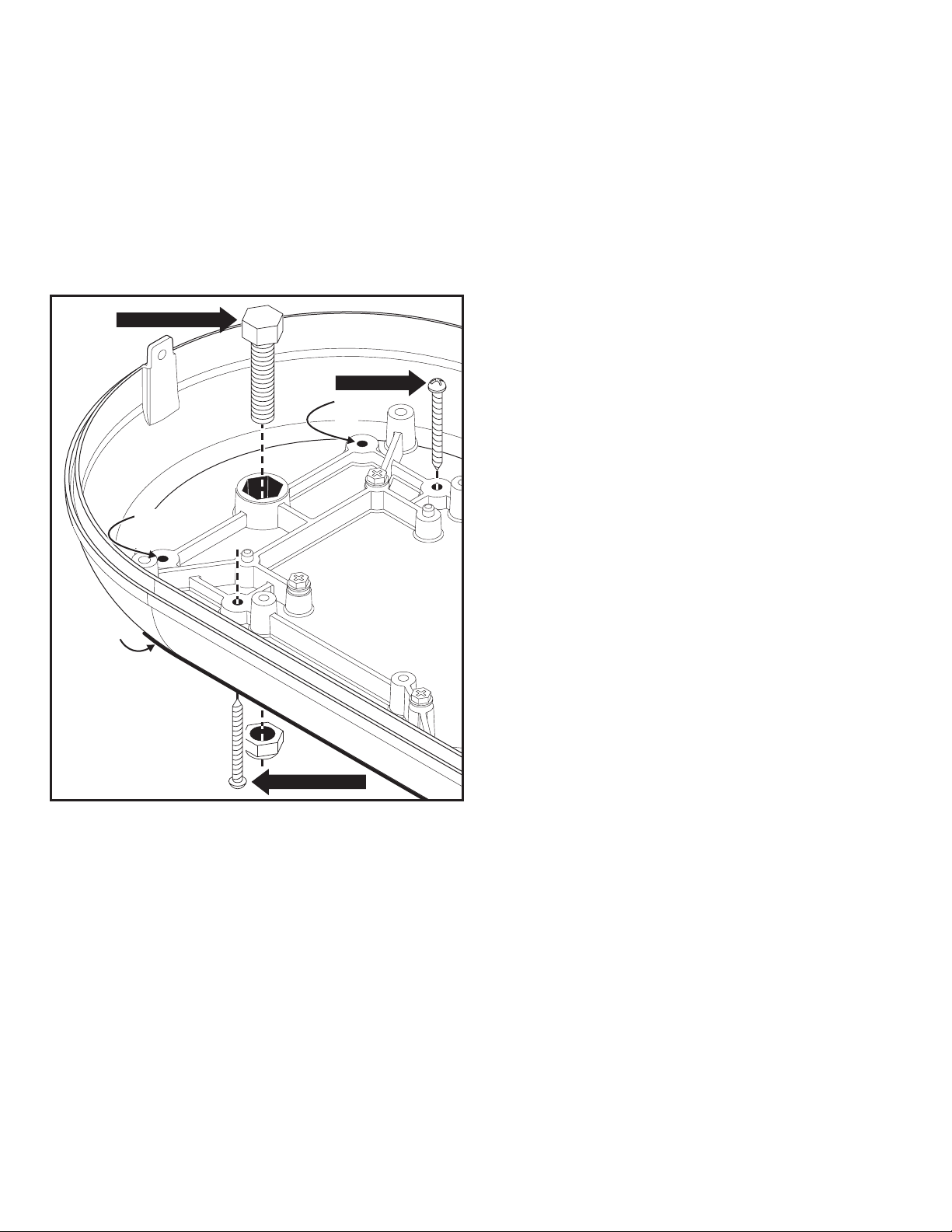
1. Be sure the mounting area is relatively flat. Using the information
in figure 2 scribe the 2 mounting hole locations onto the mounting
surface.
2. Mark off the wire access hole, located right behind the lightbar.
3. Drill the 2 mounting holes using an 11/32 drill bit and the wire
access hole using a 3/8” drill bit.
4. Tighten each locknut onto its bolt to draw the bolt head into the
base than remove the locknuts.
5. Align the bolts with the 2 mounting holes you drilled and position
the lighthead onto the mounting surface.
6. Install a 3/8” rubber access hole and route the wires through,
then apply a silicone sealing compound around the wires and
grommet.
7. Secure the lightbar with the locknuts provided.
Magnetic Mount:
Top Mount:
1. Remove the 2 screws at each end of the lightbar that secure the
dome to the base and remove the dome.
2. With a 3/16” drill bit, drill out the 4 mounting bosses in the base for
clearance holes for #8 sheet metal screws (Figs. 1 & 2).
3. Be sure the mounting area is relatively flat. Using the lightbar
base as a template, scribe the 4 mounting hole locations onto the
mounting surface.
4. Mark off the wire access hole located right behind the lightbar.
WARNING!The use of any magnetic or suction cup
mounted warning light on the outside of a vehicle, while in
motion, is not recommended and is at the sole discretion
and risk of the user.
Place the lightbar onto the vehicle, wire it to power and installation is
complete. If you have the cigarette plug model, just plug it into your
vehicle cigarette lighter and you are ready to go.
Page 2
Page 3

Fig. 2 Mounting Holes
Top view of base
WIRE EXIT HOLE HERE
4"
OPTIONAL
MOUNTING
CENTER
MOUNT
Fig. 3 Flash Tube
Replacement
MOUNTING
HOLES
LENS
SCREW
(QTY 2)
FRONT OF
LIGHTBAR
9"¾
12 "¾
Flash Tube Replacement:
1. Remove the 2 screws at each end of the lightbar that secure the
dome to the base and remove the dome.
WARNING!The strobe power supply is a high voltage device.
Do not remove flash tubes or dismantle strobe
light head assembly while in operation. Wait 10
minutes after turning power off before starting
work or trouble shooting.
FLASH TUBE
ASSY. SCREW
(QTY 2)
MOUNTING
SCREW
(QTY 3)
Note: If the edge of the base interferes with the screwdrivers
access to the lens screw, you may have to remove
the 3 mounting screws holding the beacon to the
base and lift the beacon.
2. Remove the beacons lens screws and remove the lens. If your
beacon is equipped with diamond mirrors, to gain access to the
beacon lens screws you may have to first remove the mirrors
3. Install the new flash tube making sure to align the 3 prongs on the
flash tube with the 3 slots in the power supply (Fig. 3).
4. Secure the new flash tube with its screws and reassemble the
beacon and lightbar.
Page 3
Page 4

The Guardian™ Power Supply:
If your lightbar comes equipped with the Guardian™ strobe power
supply, you will have a choice of 10 changeable flash patterns. This
power supply also comes with a Hi/Low feature to switch the beacons
from high to low power. These features are only available on
permanent mount models.
Wiring:
WARNING! The strobe light power supply is a high voltage
device. Do not touch or remove tube assembly in strobe light
head assemblies while in operation. Wait 10 minutes after
disconnecting the unit from its power source before starting
work or troubleshooting on power supply or system.
Pattern Selection
MOMENTARY
SWITCH
(For Programming)
Low Power Control
MOMENTARY
SWITCH
OR
SPST SWITCH
3 - VIOLET
4 - WHITE
WHITE
Option 1
VIOLET
Option 2
3 AMP FUSE
Fig. 4 Flash Patterns & Hi/Low
(Permanent Mount only)
1 - RED
2 - BLACK
RED
SPST SWITCH / 15 AMP
BLACK
12 VDC BATTERY
+12
VDC
10 AMP FUSE
WARNING! All customer supplied wires that connect to the
positive terminal of the battery must be sized to supply at
least 125% of the maximum operating current and FUSED
at
the battery to carry that load. DO NOT USE CIRCUIT
BREAKERS WITH THIS PRODUCT!
Note: All fuses and fuse blocks are customer supplied
1. Extend the 4 wires exiting the lightbar to the designations
shown in figure 4.
2. Connect the RED wire to a fuse block (customer supplied) and
then to the POSITIVE terminal on the battery. Do not install the
fuse until ALL of the wire connections are completed. Refer to
the wiring diagram for the appropriate fuse value needed.
3. Connect the black wire to the factory chassis ground typically
adjacent to the battery.
Low Power Control / Violet:
The type of switch used depends on how the operator wishes the Hi/
Low feature to function:
Latching Mode: By applying +voltage to the VIOLET power supply
wire for less than 1 sec., the power supply is “latched” into low power
operation. The unit must be turned off and then back on to restore
normal, Hi power operation. A momentary switch is desired for this.
Level Mode: Applying +voltage to the VIOLET power supply wire for
more than 1 sec. holds the power supply in low power mode until that
voltage is removed. A toggle switch is desired for this.
Pattern Selection / White:
This is a positive activation input. A momentary activation (less than 1
second) of the WHITE wire will change the default flash pattern to the
next available pattern. If the new pattern is active for more than 1
second, it will become the new default pattern. A momentary activation
(more than 1 second) will cause the power supply to change the
default flash pattern to the previous available pattern. If the input is tied
to positive while the unit is powered up, the default pattern will change
to CometFlash®.
Specifications: Guardian™ Power Supply
Input Voltage . . . . . . . . . . . . . . . . . . . . . 12.8 / 25.6 VDC ±20
Input Current . . . . . . . . . . . . . . . . . . . . . 3 AMP/ 1.6 AMP
Flash Rate . . . . . . . . . . . . . . . . . . . . . . . 120 CFPM
Fill Flash . . . . . . . . . . . . . . . . . . . . . . . . . 100ms
Energy . . . . . . . . . . . . . . . . . . . . . . . . . . HI 1.9/1.9/1.9/6 JOULES
LO 1.9/1.9/1.9/1.9 JOULES
Default Pattern . . . . . . . . . . . . . . . . . . . . CometFlash®
Available Flash Patterns:
1 - CometFlash® 120 . . . . . . . . . . . . . . 120 CFPM @ 200 mS/100mS
2 - TripleFlash™ 150. . . . . . . . . . . . . . . . 150 FPM @ 200 mS/100mS
3 - DoubleFlash 180 . . . . . . . . . . . . . . . . 180 FPM @ 230 mS/100mS
4 - Single Flash 400 . . . . . . . . . . . . . . . . . . . . . . 400 FPM @ 150 mS
5 - ActionFlash™ . . . . . . . . . . . . . . . . . . . . . . . . . . 3 Comet 4 Singles
6 - ModuFlash™ . . . . . . . . . . . . . . . . . .175 FPM @ 384mS to 150mS
7 - MicroBurst II™. . . . . . . . . . . . . . . . . . .200 FPM @ 200mS/100mS
8 - MicroBurst III™ . . . . . . . . . . . . . . . . . .190 FPM @ 200mS/100mS
9 - LongBurst™. . . . . . . . . . . . . . . . . . . . . . . . . . 140 FPM @ 100 mS
10 - ActionScan™ . . . . . . . . . . . . . . . . . . . . . . . All Patterns / Random
Page 4
 Loading...