

Page 1

®
ENGINEERING COMPANY INC.
51 Winthrop Road
Chester, Connecticut 06412-0684
Phone: (860) 526-9504
Liberty™ and Freedom™ Series
Installation Guide:
WeCan® Lightbars
Fax: (860) 526-4078
Internet: www.whelen.com
Sales e-mail: autosale@whelen.com
Canadian Sales e-mail: canadiansales@whelen.com
Customer Service e-mail: custserv@whelen.com
Safety First
This document provides all the necessary information to allow your Whelen product to be properly and safely installed.
Before beginning the installation and/or operation of your new product, the installation technician and operator must
read this manual completely. Important information is contained herein that could prevent serious injury or damage.
• Proper installation of this product requires the installer to have a good understanding of automotive electronics,
systems and procedures.
• Failure to use specified installation parts and/or hardware will void the product warranty!
• If mounting this product requires drilling holes, the installer MUST be sure that no vehicle components or other
vital parts could be damaged by the drilling process. Check both sides of the mounting surface before drilling
begins. Also de-burr any holes and remove any metal shards or remnants. Install grommets into all wire
passage holes.
• If this manual states that this product may be mounted with suction cups, magnets, tape or Velcro®, clean the
mounting surface with a 50/50 mix of isopropyl alcohol and water and dry thoroughly.
• Do not install this product or route any wires in the deployment area of your air bag. Equipment mounted or
located in the air bag deployment area will damage or reduce the effectiveness of the air bag, or become a
projectile that could cause serious personal injury or death. Refer to your vehicle owner’s manual for the air bag
deployment area. The User/Installer assumes full responsibility to determine proper mounting location, based
on providing ultimate safety to all passengers inside the vehicle.
• For this product to operate at optimum efficiency, a good electrical connection to chassis ground must be
made. The recommended procedure requires the product ground wire to be connected directly to the NEGATIVE
(-) battery post.
• If this product uses a remote device to activate or control this product, make sure that this control is located in
an area that allows both the vehicle and the control to be operated safely in any driving condition.
• Do not attempt to activate or control this device in a hazardous driving situation.
• This product contains either strobe light(s), halogen light(s), high-intensity LEDs or a combination of these
lights. Do not stare directly into these lights. Momentary blindness and/or eye damage could result.
• Use only soap and water to clean the outer lens. Use of other chemicals could result in premature lens cracking
(crazing) and discoloration. Lenses in this condition have significantly reduced effectiveness and should be
replaced immediately. Inspect and operate this product regularly to confirm its proper operation and mounting
condition. Do not use a pressure washer to clean this product.
• It is recommended that these instructions be stored in a safe place and referred to when performing
maintenance and/or reinstallation of this product.
• FAILURE TO FOLLOW THESE SAFETY PRECAUTIONS AND INSTRUCTIONS COULD RESULT IN DAMAGE TO
THE PRODUCT OR VEHICLE AND/OR SERIOUS INJURY TO YOU AND YOUR PASSENGERS!
Automotive: Lightbars
For warranty information regarding this product, visit www.whelen.com/warranty
©2006 Whelen Engineering Company Inc.
Form No.14084F (091610)
Page 1
Page 2
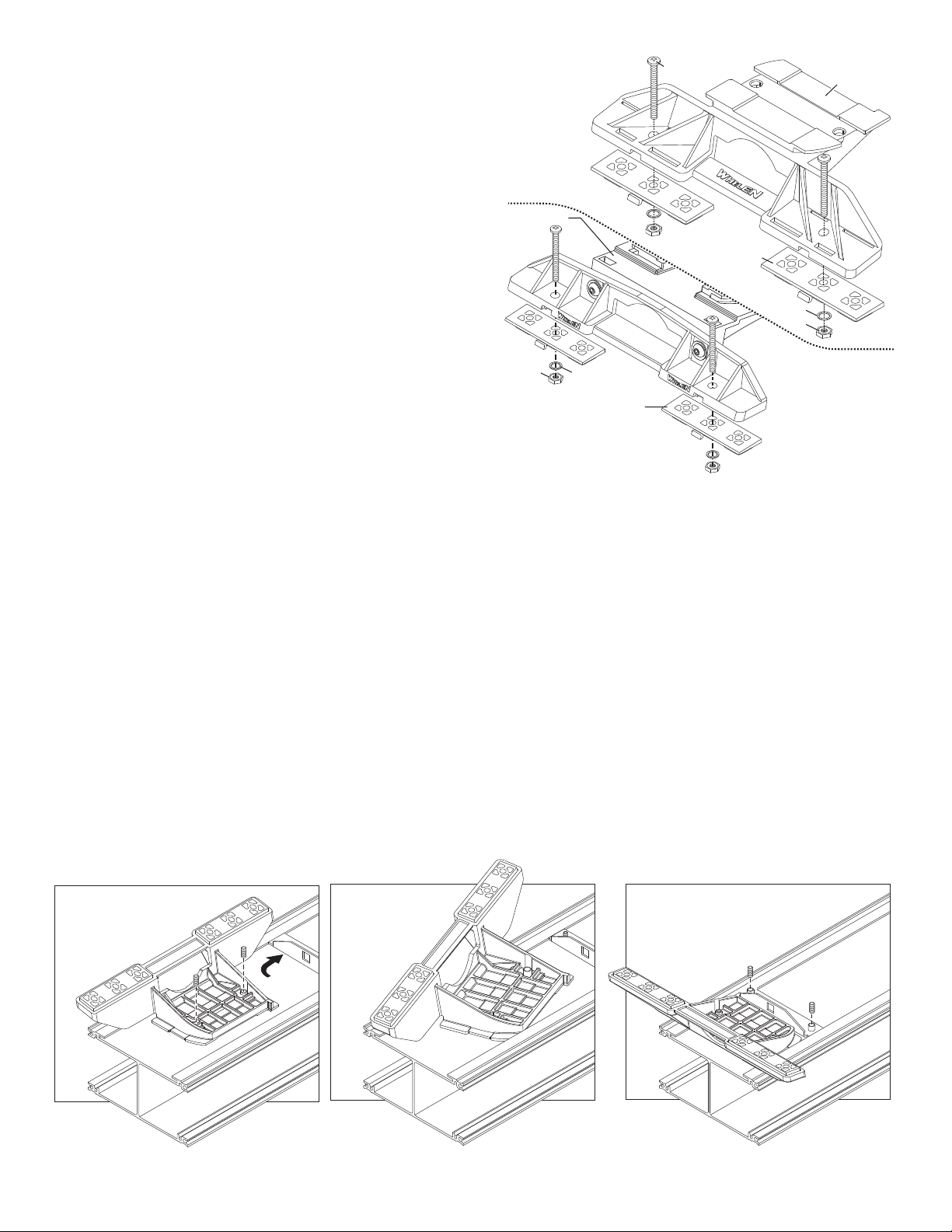
Mounting
Pad
Adjustable
Mounting
Foot
Washer
Nut
Mounting
Plate
Standard
Mounting
Foot
Mounting
Pad
Washer
Nut
Mounting
Plate
BoltBolt
IMPORTANT! The lightbar should be a minimum of 16" from any
Insert foot into extrusion with locking plate
attached.
Twist mounting foot into
position
ANCHOR
PLATE
Loosely secure foot and locking plate.
radio antennas!
Permanent Mounting:
1. Locate the mounting foot and mounting plate included with your
lightbar. If not already present, install the mounting plate onto the
mounting foot. When properly positioned, this plate is centered from
side-to-side on the mounting foot.
2. Flip the lightbar upside-down to expose the bottom of the extrusion
and place the mounting foot onto the extrusion.
3. Rotate the mounting foot 90° in a counter-clockwise direction. Make
sure that the edges of the mounting foot swing into position under the
extrusion mounting lip.
4. Repeat this procedure for the remaining mounting foot and return the
lightbar to its right side-up position.
5. Position the lightbar onto the vehicle roof in the desired mounting
location. One often selected location is directly above the B-pillars.
This area is the strongest part of the roof. Refer to your lightbar
manual for cable exit location, to be sure that the lightbar is facing the
proper direction.
6. Adjust the two mounting feet outwards so that they are as close to
the edge of the roof as possible. Make sure that both mounting feet
are in full contact with the roof. Be sure that there is no less than 1/2”
clearance between the roof and the lightbar at their closest point.
When the mounting feet are in their proper position, lightly tighten the
mounting foot allen head set screws.
7. Turn the lightbar upside-down and firmly tighten all of the set screws
from step 6 (2 or 4 per side).
8. Note that on the adjustable foot, use the hole in the pad as a guide to
drill the two holes into the mounting foot at the locations shown.
9. Place the lightbar in its final mounting position on the vehicle, mark
the mounting hole locations off onto the mounting surface, remove
the lightbar and drill the mounting holes.
10. Place the lightbar back onto the vehicle lined up with the mounting
holes and secure the mounting feet to the vehicle using the supplied
hardware as shown.
Strap Mounting:
1. Locate the mounting foot, mounting plate and tinnerman plate
included with your lightbar. If not already present, install the mounting
plate onto the mounting foot. When properly positioned, this plate is
centered from side-to-side on the mounting foot.
2. Flip the lightbar upside-down to expose the bottom of the extrusion
and place the mounting foot onto the extrusion.
3. Rotate the mounting foot 90° in a counter-clockwise direction. Make
sure that the edges of the mounting foot swing into position under the
extrusion mounting lip. Install a tinnerman plate onto the extrusion in
the same manner.
4. Repeat this procedure for the remaining mounting foot and tinnerman
plate and return the lightbar to its right side-up position.
5. Position the lightbar onto the vehicle roof in the desired mounting location.
One often selected location is directly above the B-pillars. This area is the
strongest part of the roof. Refer to your lightbar manual for cable exit
location, to be sure that the lightbar is facing the proper direction.
6. Adjust the two mounting feet outwards so that they are as close to the
edge of the roof as possible. Both mounting feet must be in full contact
with the roof. Be sure that there is no less than 1/2” clearance between
the roof and the lightbar at their closest point. When the mounting feet are
in their proper position, lightly tighten the mounting foot allen head set
screws.
7. Return the lightbar to an upside-down position. Slide each tinnerman
plate outwards until it is fully engaged with its corresponding mounting
foot. With the mounting feet and tinnerman plates in their proper positions
firmly tighten all of the set screws (2 or 4 per side). Flip the lightbar right
side-up and return it to its mounting position.
8. Open both drivers side doors. In the area directly below the mounting
foot, carefully pull the drivers side weatherstrip away from the vehicle.
Page 2
Page 3
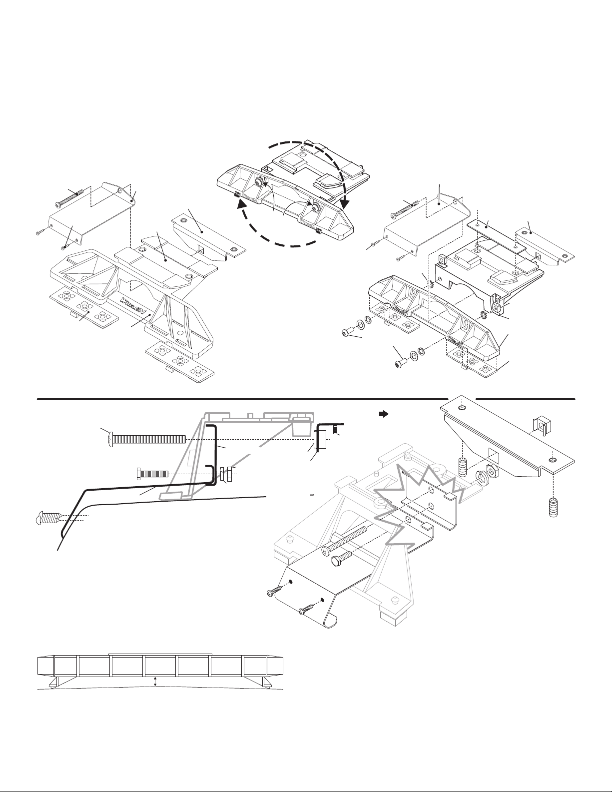
MOUNTING FOOT
TINNERMAN
NUT
FOOT
ANCHOR
PLATE
SET
SCREW
Plate slides into
lightbar extrusion
5" Mounting Foot
NUT
BOLT
SPLIT LOCK
WASHER
METAL SCREW
NOTE: The mounting straps are made to fit the contours of individual
vehicles. The strap
may look different.
shown here is for example only. The strap
for your vehicle
NOTE:
NOTE:
STRAP
SHEET
METAL
SCREWS
EXTENSION
VEHICLE ROOF
Tinnerman
Plate
Locking
Plate
Mounting
Plate
Mounting
Foot
Nut
Mounting
Pad
Adjustment
screws
Lock
Washer
Mounting
Foot
Mounting
Pad
Tinnerman
Plate
Mounting
Strap
Mounting
Screw
Tension
Bolt
Adjustable Mounting Foot / Model MKAJ
Standard Mounting Foot / Model MKEZ
Tighten screws
with torque wrench
set at 35 to 40 in/lbs
Mounting
Strap
Mounting
Screw
Tension
Bolt
Remove enough so that the area where the mounting strap will be
1/2" MIN. CLEARANCE
NOTE: Unless otherwise specified, the lightbar mounting feet must be sitting as close to the edge of the roof as possible. They must also be
in full contact with the roof and not be hanging off the edge.
IMPORTANT: For strap mounted bars, be sure you have the right sized
lightbar for your vehicle. The lightbar should be approximately the same
width as the vehicle roof. If too large or small it will not mount properly
to the vehicle and may come loose during driving.
secured to the vehicle is exposed. Repeat procedure for passenger side.
9. Insert the mounting strap through the mounting foot. Be sure that the
strap fits flush against the area where it will be secured onto the vehicle.
Insert the tension bolt through the mounting strap and into the tinnerman
nut on the tinnerman plate. Tighten slightly with a long shafted, Phillips
screwdriver. Repeat procedure for passenger side.
10. If your mounting strap has mounting holes in the end of the strap, use
these holes as a template to drill appropriately sized pilot holes through
the strap and into the vehicle. Repeat for passenger side of the vehicle.
11. Firmly tighten the tension bolts to secure the lightbar to the vehicle.
NOTE: Model MKAJ is an adjustable mounting foot. On this model you
may loosen the screws on the rear of the foot and adjust the angle of the
lightbar. This feature can be used if the angle of the roof is not level with
the road.
IMPORTANT: To adjust the leveling screws you must use a torque wrench
set at 35 to 40 in./lbs.
If your lightbar has a 5” mounting foot, it will assemble
differently than the standard mounting foot. It also uses
an extension to compensate for the extra height. Follow
these illustrations for assembly. Mounting to the lightbar
is the same.
Page 3
Page 4

IMPORTANT! It is the responsibility of the installation technician
DRILLING THE CABLE ACCESS HOLE
Drill cable access hole in appropriate area
for your lightbar (see note)
FRONT OF LIGHTBAR
For
cables exiting
the Driver-side
of the extrusion
lightbars
with
For
cables exiting
the Passenger-side
of the extrusion
lightbars
with
POWER CABLE
2.
BLACK Wire
CHASSIS GROUND
2.
COMMUNICATIONS CABLE
2. GREY / CAN L
1. GREEN / CAN H
1. +12VDC / RED Wire / Requires a fuse, customer supplied.
30 AMP Fuse: Freedom & Liberty
to make sure that the installation and operation of this product will
not interfere with or compromise the operation or efficiency of any
vehicle equipment!
Routing your Lightbar Cable(s):
1. To protect the headliner from damage caused by drilling the cable access
hole through the vehicle roof, allow a 5” to 7” distance between roof and
headliner by lowering the headliner before drilling.
2. Using a 1” hole saw, drill the cable access hole.
NOTE: There may be a roof support member that spans the distance between the driver’s and passenger’s side. DO NOT DRILL THROUGH
THIS MEMBER! Adjust the location until the hole can be drilled without contacting this support member.
3. Use a round file to smooth and de-burr the edges of the hole.
4. Install a 1” grommet (user supplied) into the cable access hole.
5. Insert the cable(s) through the cable access hole into the vehicle. Use RTV silicone to weatherproof the access hole after the cable(s) are pulled
completely into the vehicle.
Route the cable(s) one at a time to their respective destinations (power cable to vehicle battery; control cable to customer switch panel). It is left to the
installation technician's discretion to select a path for these cables that will both protect the cables from possible damage and not interfere with the
operation of any other vehicle components or equipment. Refer to the instructions included with your switches for switch wiring information.
IMPORTANT AIR BAG WARNING!Do not install this product or route any wires in the air bag deployment zone of your vehicle. Equipment
mounted or located in air bag deployment zones will damage or reduce the effectiveness of the air bag, or become a projectile that could cause
serious personal injury or death. Refer to your vehicle owners manual to learn the air bag deployment zones for the vehicle. The User/Installer
assumes full responsibility to determine proper mounting location, based on providing ultimate safety to all passengers inside the vehicle.
Connecting the Power Cable:
WARNING! All customer supplied wires that connect to the positive terminal of the battery must be sized to supply at least
125% of the maximum operating current and FUSED
at the battery to carry that load. DO NOT USE CIRCUIT BREAKERS WITH
THIS PRODUCT!
1. Follow the factory wiring harness through the firewall. It may be necessary to drill a hole in the firewall. If so, be absolutely sure that there are no
components that could be damaged by drilling. After the hole has been drilled, insert a grommet to protect the cable.
2. Route the cable along the factory wiring harness towards the battery. Install a 40 amp fuse block (customer supplied) on the end of the RED wire in
the power cable. NOTE: Remove the fuse from the fuse block before connecting any wires to the battery.
3. Connect the BLACK wire to Chassis Ground.
Connecting the Communication Cable:
Splice the GREEN and GREY wires from the lightbar to the GREEN
and GREY wires from the Whelen WC Controller.
Troubleshooting:
Your lightbar should now be fully operational. If it is not functioning
properly, check your connections for the following:
• The positive wire (RED) is properly connected to the battery,
by way of the user supplied fuse block.
• A working fuse of the correct amperage is installed in the
fuse block (See illustration above, for the specific fuse rating
for your lightbar).
• The ground wire (BLACK) is properly connected to the factory ground. Be sure that the wire is fully grounded to this location.
• The two communication wires (GREEN and GREY) are properly connected to their communication designations.
If these connections are good, contact your Whelen® representative for further assistance.
Page 4
Page 5

Lighthead mounting holes
snap into the raised bosses
on the lighthead bracket.
Ears on lighthead bracket
slide inton channels in
extrusion (base).
Snap lighthead
into bracket.
Mounting Lightheads to Extrusion
BASE
EXTRUSION
LR-11 Take-down and Alley Light
LR-11 Alley Light
BASE EXTRUSION SIDE VIEW
LIGHTHEAD
Endcap, Gasket , Lenses & Spacers Installation
Gasket & Halogen Alley Light
BARB
BOSS
Halogen Lighthead
snaps into extrusion
Align lighthead
reflector up with 4
bosses in endcap.
Press reflector into
place.
Servicing: Liberty Lightbar
Servicing: Freedom™ Lightbar
Remove the screws (A) that hold the endcap on and pull the endcap and gasket (C) off.4 (B) Slide lenses
(D) out of the lightbar, to gain access to the extrusion. When reinstalling the lenses and spacers, install the
cord seal (NFPA / See below). When reinstalling the endcap, place the endcap gasket into it's position on
the endcap and line up all the tabs and holes. Spacers (not shown) mount the same as lenses.
D
D
C
Insert cord seal into track in lens
A
B
Seal Cord Installation / NFPA Only:
Cut the seal cord approx. 1-1/2" longer than the extrusion on each side.
Rub silicone over the cord seal leaving 3 to 4 inches on one end dry.
Begining with 1 corner lens, start the lens into the bottom
lens track. Place the cord seal onto the groove in the
top of the lens eav 1 to 2 inches
Hold onto the left end of the seal hanging
out and slide the corner lens into
position.
1 2 3 -
4 -
3 3 -
4 4 -
. L e free.
Inspect seal cord for any areas that have wrinkled.
Especially in the areas around the dividers.
Push the lenses together tight and trim excess seal
cord at each end.
6 -
7 -
6 -
7 -
From the opposite end of the
lightbar, pull the seal
cord tight and install
the remaining lenses
and divider.
5 -
5 5 5 5 -
NOTE: Lens dividers must
be installed as each lens is
put into position
Installing Corner Linear-LED®
Insert the tabs on the lighthead housing, into the channels in the extrusion.
Installing Lens and Lighthead
Lens
fits
here
Extrusion secures to Support Bracket.
SUPPORT
BRACKET
BASE EXTRUSION
SUPPORT
BRACKET
SECURE TO
EXTRUSION
TO SECURE
BRACKET
EXTRUSION
LR11 TAKEDOWN
LR11
ALLEY
LIGHT
BASE
EXTRUSION
LR-11 Take-down
A
D
J
U
S
T
A
N
G
L
E
Slide into
tracks in
extrusion
Secure lighthead
bracket to extrusion
Snap lighthead
bracket into TD
bracket
Mounting Endcap
Endcap
Lens
Screw
Page 5
Page 6

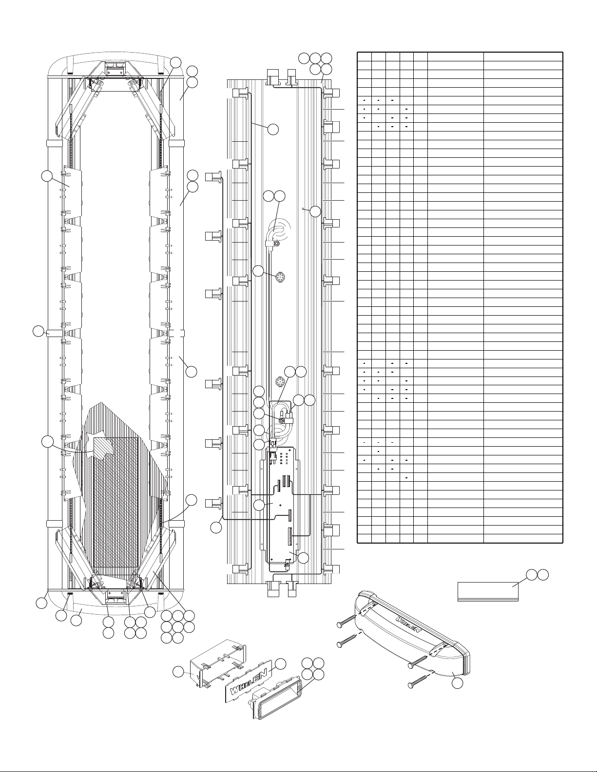
L6F
L6R
F6
PASSENGER
YELLOW
PASS. ALLEY
PTD
LA2
L7R
LA4
L5F
L4F
L3F
L2F
L1F
REAR OF LIGHTBAR
L5R
F5
L4R
F4
L3R
F3
L2R
L1R
F2
F1
DTD
LA3
DRIVER
L7F
WHITE
DRIVER
ALLEY
LA1
46-0784851-01
46-0743196-17
01-0264939-00
46-0985997-00
46-0743442-02
01-026B807-20
01-026B807-50
01-026B807-40
01-026B807-30
01-026B807-10
11-363390-000
10-0523067-02
14-104216-160
01-0684668-
01-068466801-0684668-
11-363141-000
11-363142-000
11-363143-000
22-0542701-00
21-242401-000
21-11245004-1
13-104111-063
13-130111-072
22-0416982-00
01-0684668-
26-0115037-08
12
1111
1
1
1
111
1
2
1
1
4
3
5
1
4
2
1
2
2
4
2
2
4
2
2
1
2
1
1
2
1
4
2
2
7
6
8
1
2
1
10
9
11
1111
18
A/R
1
1
1
A/RA/R
111
1
11
A/R
15
1
1
13
14
1
17
1
2
2
121
2
2 2
1
2
20
19
21
2
23
22
24
Freedom™ WeCan® R/R/B/B 44"
Freedom™ WeCan® R/R/B/B 50"
Freedom™ WeCan® R/R/B/B 55"
Freedom™ WeCan® R/R/B/B 60"
HARNESS, TA, FREEDOM WC
POWER/COMM. "WC"
NUT, 1/4-20 ELASTIC STOP (316 SS)
NUT, #10-24 WHIZ
BASE EXTRUSION (40.375")
LABEL, MODEL & SERIAL NO.
#10-24 x 1 PPHMS
GROMMET, 1.562"
PROTECTIVE COVER
BASE EXTRUSION (45.75")
BASE EXTRUSION (51.125")
BASE EXTRUSION (56.50")
MTG. STUD
BUSHING, 1-5/8"
HARNESS, INT. FREEDOM "WC"
CABLE, 2/C 20GA 17'
CABLE, 2/C 10GA (17')
CORNER REFLECTOR LED BLU
CORNER REFLECTOR LED RED
CORNER REFLECTOR LED GRN
CORNER REFLECTOR LED WHT
CORNER REFLECTOR LED AMB
CABLE CLAMP, 1/2"
46-0743442-03
46-0743196-25
20-0042765-00
01-0286361255
01-0286361244
01-0286361233
01-0286361222
01-0286361211
10-0322935-00
21-7263998-00
01-026C368-30
68-1984105-30
68-1183491C02
07-242815-000
68-1983816-30
68-1983817-30
68-1984104-30
38-0283381-00
02-0341448-30
68-1183369-30
09-1363158-00
07-263103-000
14-104286-16JB
31
444
A/R
12
18
A/RA/R
10
12
1
16
18
1
222
A/R
28
12
14
11
26
25
27
22
29
30
2
2
4
4
6
8
22
2
8
8
2
8
8
2
34
32
33
2
6
8
35
37
36
A/RA/RA/RA/R
A/R
A/R
A/R
A/R
4
4
A/R
2
4
A/R
A/R
A/R
A/R
A/R
A/R
A/R
4
A/R
39
38
40
A/R
A/R
A/R
42
41
43
A/R
A/R
4
A/R A/R
4
A/R4A/R
A/R
47
4
A/R
45
44
46
SINGLE LR11 ALLEY FREEDOM
#10-24 x 1-1/4" TX. PHD. SCREW SHLDR
LABEL, "FRONT"
VENT, 3/4"
GASKET, ENDCAP
ENDCAP, CLEAR
LENS, 5.00" CLEAR
LENS DIVIDER ASS'Y. (CLEAR)
FILLER PANEL, "400" SERIES
MOUNTING BRACKET
BRACKET, SPACER
LENS, 6.562" CLEAR
LENS, 9.25" CLEAR
CABLE, 2/C 20GA 25'
CABLE, 2/C 10GA (25')
SPACER CORNER STROBE
LINEAR LED 400 RED GEN III AMP
LINEAR LED 400 GRN GEN III AMP
LINEAR LED 400 WHT GEN III AMP
LINEAR LED 400 BLU GEN III AMP
LINEAR LED 400 AMB GEN III AMP
LENS, 15.75" CLEAR
LENS, 10.375" CLEAR
DESCRIPTION
PART NUMBER
ITEM
QTY.QTY.QTY.QTY.
*
*
*
*
20
1
21
2
22
3
23
4
24
5
FRONT
37
39
47
38
29
9
30
17
19
18
15
6
18
8
14
10
39
36
31
32
34
45
35
27
26
25
33
11
12
13
7
45
40 41 42 43 44
28
Page 6
Page 7

33
46-0784851-01
46-0743196-17
01-0264939-00
46-0985997-00
46-0743442-02
01-026B805220
01-026B805550
01-026B805440
01-026B805330
01-026B805110
11-363390-000
10-0523067-02
14-104216-160
01-0684668-
01-0684668-
01-0684668-
11-363141-000
11-363142-000
11-363143-000
22-0542701-00
21-242401-000
21-11245004-1
13-104111-063
13-130111-072
22-0416982-00
01-0684668-
26-0115037-08
12
1
111
1
1
1
111
1 2
1
1
4
3
5
1
4
2
1
2
2
4
2
2
4
2
2
1
2
1
1
2
1
4
2
2
7
6
8
1
2
1
10
9
11
111
1
18
A/R
1
1
1
A/RA/R
111
1
11
A/R
15
1
11314
1 17
1
2
2
121
2
2 2
1
2
20
19
21
2
23
22
24
Freedom™ WeCan® R/R/B/B 44"
Freedom™ WeCan® R/R/B/B 50"
Freedom™ WeCan® R/R/B/B 55"
Freedom™ WeCan® R/R/B/B 60"
HARNESS, TA, FREEDOM WC
ASSEMBLY, POWER/COMM. "WC"
NUT, 1/4-20 ELASTIC STOP (316 SS)
NUT, #10-24 WHIZ
BASE EXTRUSION (40.375")
LABEL, MODEL & SERIAL NO.
#10-24 x 1 PPHMS
GROMMET, 1.562"
PROTECTIVE COVER
BASE EXTRUSION (45.75")
BASE EXTRUSION (51.125")
BASE EXTRUSION (56.50")
MTG. STUD
BUSHING, 1-5/8"
HARNESS, INTERNAL FREEDOM "WC"
CABLE, 2/C 20GA 17'
CABLE, 2/C 10GA (17')
CORNER REFLECTOR LED BLUE
CORNER REFLECTOR LED RED
CORNER REFLECTOR LED GREEN
CORNER REFLECTOR LED WHITE
CORNER REFLECTOR LED AMBER
CABLE CLAMP, 1/2"
46-0743442-03
46-0743196-25
01-0286361222
01-0286361233
01-0286361244
01-0286361255
01-0286361211
10-0322935-00
21-7263998-00
01-026C368-30
68-1984105-30
68-1183491C02
07-242815-000
68-1983816-30
68-1983817-30
68-1984104-30
38-0283381-00
02-0341448-30
68-1183369-30
09-1363158-00
07-263103-000
14-104286-16JB
31
444
A/R
12
18
A/RA/R
10
12
1
16
18
1
222
A/R
28
12
14
1
1
26
25
27
2
2
29
30
2
2
4
4
6
8
22
2
8
8
2
8
8
2
34
32
33
2
6
8
35
37
36
A/R
A/R
A/RA/R
A/R
A/R
A/R
A/R
4
4
A/R
2
4
A/R
A/R
A/R
A/R
A/R
A/R
A/R
4
A/R
39
38
40
A/R
A/R
A/R
42
41
43
A/R
A/R
A/R
A/R
A/R
A/R
A/R
A/R
45
44
46
SINGLE LR11 ALLEY FREEDOM
#10-24 x 1-1/4" TX. PHD. SCREW W/SHOULDER
LABEL, "FRONT"
VENT, 3/4"
GASKET, ENDCAP
ENDCAP, CLEAR
LENS, 5.00" CLEAR
LENS DIVIDER ASS'Y. (CLEAR)
FILLER PANEL, "400" SERIES
MOUNTING BRACKET
BRACKET, SPACER
LENS, 6.562" CLEAR
LENS, 9.25" CLEAR
CABLE, 2/C 20GA 25'
CABLE, 2/C 10GA (25')
LINEAR LED 400 RED GEN III AMP
LINEAR LED 400 GREEN GEN III AMP
LINEAR LED 400 WHITE GEN III AMP
LINEAR LED 400 BLUE GEN III AMP
LINEAR LED 400 AMBER GEN III AMP
LENS, 15.75" CLEAR
LENS, 10.375" CLEAR
ITEM
PART NUMBER
DESCRIPTION
QTY QTY QTY QTY
FRONT
23
21
20
22
24
30
27
38
39
39
36
35
32
31
37
26
33
25
34
40 41 42 43 44
28
F6
L6R
L6F
YELLOW
PASS
ALLEY
PASSENGER
PTD
LA2
L7R
LA4
15
L5F
13
11
12
L4F
L3F
L2F
L1F
REAR OF LIGHTBAR
L5R
F5
L4R
F4
L3R
F3
L2R
L1R
F2
F1
DTD
LA3
DRIVER
L7F
DRIVER
ALLEY
WHITE
3
21
5
4
LA1
19
19
9
18
6
7
8
18
45
14
10
17
46
29
Page 7
Page 8
DRIVER
ALLEY
WHITE
L7F
LA3
F1
F2
F3
61
8
7
F4
F5
FRONT OF LIGHTBAR
DTD
L1F
L2F
L3F
L4F
L5F
F6
L6F
PTD
LA2
15
14
60
5
13
12
11
9
6
60 61
18
3
21
45
4
19
LA1
L1R
L2R
L3R
L4R
L5R
L6R
LA4
9
PASS.
ALLEY
YELLOW
L7R
57
64
47
50
49
44
43
62
63
36
25 26
27
28
21 22
23
24
33
29
20
30 31
32
CENTER LENS FOR 43" & 60"
46 49
43
37
3938
11
41
58
48
20
42
FRONT OF LIGHTBAR
34
8668
28282
88
2
1
1
11
2
4
44
2
4 4
4
4
4
4444
1111
A/RA/RA/RA/R
A/R A/R A/R A/R
2222
A/R A/R A/R A/R
1111
02-0342791-30
02-036E683-30
14-104286-16J
42
43
44
#10-24 x 1-1/4" TX. PHD W/SHLDR
LENS, OVERMOLD ENDCAP CLEAR
ASS'Y, LENS DIVIDER (CLEAR)
45 10-0522960-00
LABEL, MODEL & SERIAL NO.
46
68-1983818-30
LENS, 5.062" LG (CLEAR)
47
68-1983819-30
LENS, 5.687" LG (CLEAR)
49
68-1963333C08
68-1963333C03
50
68-1983567-30
48
LENS, 8.375" LG (CLEAR)
LENS, 10.500" LG (CLEAR)
LENS, 15.800" LG (CLEAR)
57
SPACER, CORNER RETENTION
20-0042765-00
10-0322935-00
LABEL, "FRONT" LIGHTBAR ASSY
58
61
60
46-0743442-03
46-0743196-25
CABLE, 2/C 10GA (25')
CABLE, 2/C 20GA (25')
SUB ASSY, END SUPPORT BRKT
02-036B855-00
62
SUB ASSY, LR11 ALLEY WHITE
02-036B855-30
63
INSULATOR, FOAM PAD
38-0142783-00
64
DESCRIPTION
PART NUMBER
ITEM
QTY.QTY.QTY.QTY.
1
2
1
1
1
1
22
1121
1
1
A/R
1
1
1
A/R
111
1
A/R
1
1
A/R
1
1
1
1
1
1
1
1
1
2
1
6
16
1
22
1121
12
66
12
11
6
10
1
A/R
A/R
A/R
A/R
A/R
A/R
A/R
A/RA/R A/R
A/R
A/R
A/R
A/R
A/R
A/R
A/R
A/R
A/R
A/R
A/R
A/RA/R
A/R
A/R
A/R
A/R
A/R
CORNER 9 WHT LIBERTYLED
CORNER 9 BLU LIBERTY
LED
CORNER 9 AMB LIBERTYLED
CORNER 12 RED LIBERTYLED
CORNER 12 WHT LIBERTYLED
CORNER 12 BLU LIBERTYLED
CORNER 12 LED AMB LIBERTY
SCREW,#6-32 x 1/2" PPHMS SS
HOUSING, LIGHTHEAD (SNAP IN)
HARNESS, LIBERTY "WC" LTBAR
#10-24 x 3/8 PPH SCREW
14-062216-080
11-483564-000
46-0985994-00
14-104216-06J
01-026B625910
01-026B625920
01-026B625930
01-026B625250
01-026B625230
01-026B625220
01-026B625210
A/R
16
A/R
A/R
A/R
A/R
A/RA/R A/R
A/R
A/R
1212
A/R
A/R
10
A/R
A/R
A/R
A/R
A/R
A/R
4
A/R
A/R
1
1
1
1
SUB ASS'Y, 500 CREE LED, BLU, W/2POS AMP
SUB ASS'Y, 500 LED, RED, 2 POS AMP
SUB ASS'Y, 500 LED, WHT, 2 POS AMP
CORNER 9 RED LIBERTYLED
SUB ASS'Y, 500 LED, AMB, 2 POS AMP
EXTRUSION, TOP 54.78"
EXTRUSION, TOP 49.39"
EXTRUSION, TOP 44.00"
EXTRUSION, TOP 38.61"
SPACER, CORNER
PANEL, FILLER (500 SERIES)
01-026B625950
07-243170-000
01-026B827630
01-026A068220
01-026B827610
01-026B827650
09-1363542-00
11-26B607-038
11-26B607-044
11-26B607-054
11-26B607-049
3
1
2
4
6
5
8
7
9
11
13
12
15
14
18
19
20
24
22
21
23
25
27
26
31
29
28
30
32
33
34
36
37
38
39
HARNESS, TA LIBERTY WC
POWER/COMM "WC"
#10-24 WIZ NUT
SCREW, 10-24 x 1.25" TX PHD
CABLE CLAMP 1/2"
46-0784851-00
14-0023347-00
13-104111-063
26-0115037-08
01-0264940-00
CABLE, 2/C 20GA (17')
PLUG, VENT (3/4")
BASE, EXTRUDED (54.78")
BASE, EXTRUDED (49.39")
BASE, EXTRUDED (44.00")
CABLE, 2/C 10GA (17')
GROMMET, 1.562
BASE, EXTRUDED (38.61")
21-7263998-00
11-363312-054
11-363312-049
11-363312-044
21-11245004-1
11-363312-038
46-0743196-17
46-0743442-02
L ™ 43" W SeriesIBERTY ECAN™
01-0684682-
LIBERTY™ 60" WECAN™Series
LIBERTY™ 48" WECAN™Series
LIBERTY™ 54" WECAN™Series
01-068468201-0684682-
01-0684682-
*
*
*
*
Page 8
Page 9

20
45
27 28 29 30 31
26
19
CENTER LENS FOR 43" & 60"
44 47
46
WHITE
DRIVER
ALLEY
L7F
4
3
21
LA3
48
47
6
56
8
7
5
13
12
11
FRONT OF LIGHTBAR
FRONT OF LIGHTBAR
DTD
L1F
L2F
L3F
L4F
L5F
63
42
34 35
36 37
52
25
32
60
57
58
21
59
23
YELLOW
PASS. ALLEY
L7R
L6F
PTD
LA2
19
55
9
14
F3
F4
F5
F6
LA1
L1R
L2R
L3R
L4R
L5R
L6R
41
61
2422
9
15
18
40
62
53
43
F1
F2
LA4
56
55
LIBERTY 54" / EX CRNR / WECAN™
LIBERTY 48" / EX CRNR / WECAN™
LIBERTY 60" / EX CRNR / WECAN™
LIBERTY 43" / EX CRNR / WECAN™
OVERMOLD ENDCAP CLR
02-036E683-30
3
1
2
4
6
5
8
7
9
11
13
12
15
14
18
19
20
24
22
21
23
25
27
26
41
31
29
28
30
32
34
36
35
37
40
48
43
42
44
46
45
47
52
53
55
56
60
58
57
59
61
62
DESCRIPTION
PART NUMBER
ITEM
QTY.QTY.QTY.QTY.
*
*
*
*
SUB ASY, END SUP. BRCKT
INSULATOR, FOAM PAD
EXT. CORNER 18 LED BLU
EXT. CORNER 18 LED WHT
EXT. CORNER 18 LED GRN
EXT. CORNER 18 LED RED
EXT. CORNER 18 LEDAMB
HARNESS, TA LIBERTY WC
SUB ASY, 500 LED, AMB, 2 POS AMP
EXT. CORNER 12 LEDAMB
POWER/COMM "WC"
#10-24 WIZ NUT
SCREW, 10-24 x 1.25" TX PHD
CABLE CLAMP 1/2"
EXT. CORNER 12 LED GRN
EXT CORNER 12 RED. LED
EXT CORNER 12 WH. LED T
EXT CORNER 12 BLU. LED
PANEL, FILLER (500 SERIES)
#10-24 x 3/8 PPH SCREW
HARNESS, LIBERTY "WC"
#6-32 x 1/2" PPHMS SS
CABLE, 2/C 10GA (25')
SUB AS'Y, 500 CREE LED, BLU, 2POS AMP
SUB AS'Y, 500 LED, GRN, 2 POS AMP
#10-24 x 1-1/4" TX. PHD W/SHLDR
SUB AS'Y, 500 LED, WHT, 2 POS AMP
SUB AS'Y, 500 LED, RED, 2 POS AMP
ADJ. LR-11 ALLEY LIGHT
LENS DIVIDER (CLR)
SPACER, CORNER
EXTRUSION, TOP 38.61"
EXTRUSION, TOP 44.00"
EXTRUSION, TOP 49.39"
EXTRUSION, TOP 54.78"
LABEL, "FRONT" LT. BAR
LABEL, MODEL & SERIAL NO.
LENS, 5.062" LG (CLEAR)
LENS, 5.687" LG (CLEAR)
LENS, 8.375" LG (CLEAR)
LENS, 10.500" LG (CLEAR)
LENS, 15.800" LG (CLEAR)
CABLE, 2/C 20GA (25')
CABLE, 2/C 20GA (17')
PLUG, VENT (3/4")
BASE, EXTRUDED (54.78")
BASE, EXTRUDED (49.39")
BASE, EXTRUDED (44.00")
CABLE, 2/C 10GA (17')
GROMMET, 1.562
BASE, EXTRUDED (38.61")
HSNG, LIGHTHEAD (SNAP IN)
A/R
A/R
A/R
A/R
A/R
A/R A/RA/R
A/R
A/R
A/R
A/R
A/R
A/R
A/R
A/R
A/R
A/R
11
A/R
A/R
1
222
38-0142783-00
01-026B693820
01-026B693840
01-026B693850
01-026B693830
01-026B693810
1
02-036B855-00
2
1
1
2
1
1
1
2
121 1
2
1
1
A/R
1
1
1
A/R
111
1
A/R
1
1
A/R
11
111
1
1
1
1
2
1
6
1
16
22
1121
12
66
12
1161
10
A/R
A/R
A/R
A/R
A/R
A/R
16
A/RA/R A/R
A/R
A/R
A/R
A/R
A/R
A/R
A/R
A/R
A/R
12
A/R
A/RA/R
A/R
12
A/R
A/R
10
46-0784851-00
14-0023347-00
13-104111-063
26-0115037-08
14-104216-06J
46-0985994-00
11-483564-000
14-062216-080
01-0264940-00
09-1363542-00
01-026B827610
01-026B693210
01-026B693220
01-026B693230
01-026B693250
01-026B693240
A/RA/RA/RA/R
2222
A/R
A/R
A/R
A/R
A/RA/RA/R
A/R
A/R
A/R
A/R
A/R
A/R
A/R
A/R
A/R
4
1
1
8
1
1
668
444
1
8
4
2
8118
1
8
2
444
4
A/R1A/R A/R A/R
111
A/R A/RA/R A/R
46-0743196-25
01-026B827640
11-26B607-038
01-026B827650
01-026A068220
01-026B827630
07-243170-000
02-0342791-30
11-26B607-049
11-26B607-054
11-26B607-044
68-1983567-30
14-104286-16J
10-0522960-00
68-1983818-30
68-1983819-30
10-0322935-00
01-026B855-30
46-0743442-03
21-7263998-00
11-363312-054
11-363312-049
11-363312-044
21-11245004-1
11-363312-038
46-0743196-17
46-0743442-02
01-0684682-
01-068468201-0684682-
01-0684682-
68-1963333C03
68-1963333C08
63
Page 9
 Loading...