

Page 1

®
ENGINEERING COMPANY INC.
51 Winthrop Road
Chester, Connecticut 06412-0684
Phone: (860) 526-9504
Fax: (860) 526-4078
Internet: www.whelen.com
Sales e-mail: autosale@whelen.com
Canadian Sales e-mail: canadiansales@whelen.com
Customer Service e-mail: custserv@whelen.com
Installation Guide:
Freedom™ HC Lightbar
Rota-Beam™ Series
Whelen’s emergency vehicle warning devices must be properly mounted and wired in order to be effective and safe. Read and follow all of Whelen’s
written instructions when installing or using this device. Emergency vehicles are often operated under high speed stressful conditions which must be
accounted for when installing all emergency warning devices. Controls should be placed within convenient reach of the operator so that he can operate
the system without taking his eyes off the roadway. Emergency warning devices can require high electrical voltages and/or currents. Properly protect and
use caution around live electrical connections.Grounding or shorting of electrical connections can cause high current arcing, which can cause personal
injury and/or vehicle damage, including fire. Many electronic devices used in emergency vehicles can create or be affected by electromagnetic
interference. Therefore, after installation of any electronic device it is necessary to test all electronic equipment simultaneously to insure that they operate
free of interference from other components within the vehicle. Never power emergency warning equipment from the same circuit or share the same
grounding circuit with radio communication equipment. All devices should be mounted in accordance with the manufacturer’s instructions and securely
fastened to vehicle elements of sufficient strength to withstand the forces applied to the device. Driver and/or passenger air bags (SRS) will affect the way
equipment should be mounted. This device should be mounted by permanent installation and within the zones specified by the vehicle manufacturer, if
any. Any device mounted in the deployment area of an air bag will damage or reduce the effectiveness of the air bag and may damage or dislodge the
device. Installer must be sure that this device, its mounting hardware and electrical supply wiring does not interfere with the air bag or the SRS wiring or
sensors. Mounting the unit inside the vehicle by a method other than permanent installation is not recommended as unit may become dislodged during
swerving; sudden braking or collision. Failure to follow instructions can result in personal injury. Whelen assumes no liability for any loss resulting from the
use of this warning device. PROPER INSTALLATION COMBINED WITH OPERATOR TRAINING IN THE PROPER USE OF EMERGENCY WARNING
DEVICES IS ESSENTIAL TO INSURE THE SAFETY OF EMERGENCY PERSONNEL AND THE PUBLIC.
Warnings to Users
Warnings to Installers
Whelen’s emergency vehicle warning devices are intended to alert other operators and pedestrians to the presence and operation of emergency vehicles
and personnel. However, the use of this or any other Whelen emergency warning device does not guarantee that you will have the right-of-way or that
other drivers and pedestrians will properly heed an emergency warning signal. Never assume you have the right-of-way. It is your responsibility to proceed
safely before entering an intersection, driving against traffic, responding at a high rate of speed, or walking on or around traffic lanes. Emergency vehicle
warning devices should be tested on a daily basis to ensure that they operate properly. When in actual use, the operator must ensure that both visual and
audible warnings are not blocked by vehicle components (i.e.: open trunks or compartment doors), people, vehicles, or other obstructions. It is the user’s
responsibility to understand and obey all laws regarding emergency warning devices. The user should be familiar with all applicable laws and regulations
prior to the use of any emergency vehicle warning device. Whelen’s audible warning devices are designed to project sound in a forward direction away
from the vehicle occupants. However, because sustained periodic exposure to loud sounds can cause hearing loss, all audible warning devices should be
installed and operated in accordance with the standards established by the National Fire Protection Association.
Safety First
This document provides all the necessary information to allow your Whelen product to be properly and safely installed. Before beginning the installation
and/or operation of your new product, the installation technician and operator must read this manual completely. Important information is contained herein
that could prevent serious injury or damage.
• Proper installation of this product requires the installer to have a good understanding of automotive electronics, systems and procedures.
• Whelen Engineering recommends the use of waterproof butt splices and/or connectors if that connector could be exposed to moisture.
• Failure to use specified installation parts and/or hardware will void the product warranty.
• If mounting this product requires drilling holes, the installer MUST be sure that no vehicle components or other vital parts could be damaged
by the drilling process. Check both sides of the mounting surface before drilling begins. Also de-burr the holes and remove any metal shards
or remnants. Install grommets into all wire passage holes.
• If this manual states that this product may be mounted with suction cups, magnets, tape or Velcro®, clean the mounting surface with a 50/50
mix of isopropyl alcohol and water and dry thoroughly.
• Do not install this product or route any wires in the deployment area of your air bag. Equipment mounted or located in the air bag deployment
area will damage or reduce the effectiveness of the air bag, or become a projectile that could cause serious personal injury or death. Refer to
your vehicle owner’s manual for the air bag deployment area. The User/Installer assumes full responsibility to determine proper mounting
location, based on providing ultimate safety to all passengers inside the vehicle.
• For this product to operate at optimum efficiency, a good electrical connection to chassis ground must be made. The recommended
procedure requires the product ground wire to be connected directly to the NEGATIVE (-) battery post (this does not include products that use
cigar power cords).
• If this product uses a remote device for activation or control, make sure that this device is located in an area that allows both the vehicle and
the device to be operated safely in any driving condition.
• Do not attempt to activate or control this device in a hazardous driving situation.
• This product contains either strobe light(s), halogen light(s), high-intensity LEDs or a combination of these lights. Do not stare directly into
these lights. Momentary blindness and/or eye damage could result.
• Use only soap and water to clean the outer lens. Use of other chemicals could result in premature lens cracking (crazing) and discoloration.
Lenses in this condition have significantly reduced effectiveness and should be replaced immediately. Inspect and operate this product
regularly to confirm its proper operation and mounting condition. Do not use a pressure washer to clean this product.
• It is recommended that these instructions be stored in a safe place and referred to when performing maintenance and/or reinstallation of this
product.
• FAILURE TO FOLLOW THESE SAFETY PRECAUTIONS AND INSTRUCTIONS COULD RESULT IN DAMAGE TO THE PRODUCT OR VEHICLE
Automotive: Lightbars
AND/OR SERIOUS INJURY TO YOU AND YOUR PASSENGERS!
©2013 Whelen Engineering Company Inc.
Form No.14691 (050613)
For warranty information regarding this product, visit www.whelen.com/warranty
Page 1
Page 2
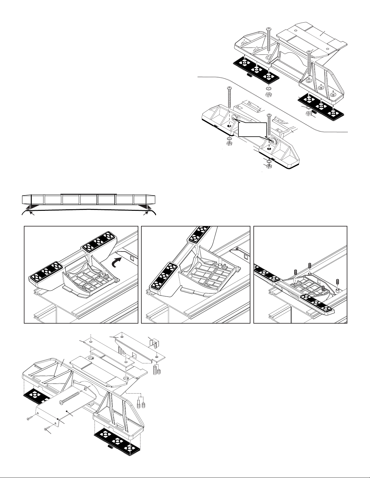
Mounting
Foot
Tinnerman
Nut
Anchor
Plate
Locking
Plate
Mounting
Strap
Mounting Screw
Tension Bolt
Fig. 5
Mounting
Pad
Adjustable
Mounting Foot
Model MKAJ
Washer
Nut
BoltBoltBolt
Mounting
Plate
Mounting
Plate
Standard
Mounting
Foot
Model MKEZ
Fig. 1
Washer
Nut
TIGHTEN SCREWS
WITH TORQUE
WRENCH SET AT
35 TO 40 IN/LBS
Mounting
Pad
IMPORTANT! The lightbar must be a minimum of 16” from radio
IMPORTANT: Unless otherwise specified, the lightbar mounting feet must be sitting
as close to the edge of the roof as possible. Mounting feet must also be in full
contact with the roof and not be hanging off the edge. For strap mounted bars, the
lightbar should be about the same width as the vehicle roof. If the lightbar is too
large or small it will not mount properly to the vehicle and may shift or come loose
during driving.
1/2" Minimum Clearance at Closest Point
Loosely secure foot and locking plate.
Insert foot into extrusion with
locking plate attached.
ANCHOR
PLATE
Twist foot
into position
Fig. 2 Fig. 3 Fig. 4
antennas!
Permanent Mounting:
1. Locate the mounting foot and locking plate included with your lightbar. If not
already present, install the locking plate onto the mounting foot using the
supplied allen set screws (Fig. 1).
2. Flip the lightbar upside-down to expose the bottom of the extrusion. Place the
mounting foot into the extrusion and rotate the foot so that the top of the foot
swings into position under the lips in the extrusion (Figs. 2, 3 & 4). NOTE: You
do not need the anchor plate shown in Figs. 2 - 4. This is used in strap
mounting.
3. Repeat this procedure for the remaining mounting foot and return the lightbar
to its right side-up position.
4. Position the lightbar onto the vehicle roof in the desired mounting location. One
often selected location is directly above the B-pillars. This area is the strongest
part of the roof. Check the light bar cable exit location to be sure that the
lightbar is facing the proper direction (Cable exits in rear).
5. Adjust the mounting feet outwards so that they are as close to the edge of the
roof as possible (See below). When the mounting feet are properly positioned,
lightly tighten the allen head set screws.
6. Turn the lightbar upside down and firmly tighten all of the mounting foot allen head set screws
(Fig.4). With the lightbar upside down, drill 2 holes into the mounting foot (for the mounting
bolts) using the holes in the mounting pads as guides, in the location shown in figure 1.
7. Place the lightbar in its final mounting position on the vehicle, mark the mounting hole locations off onto
the mounting surface, remove the lightbar and drill the mounting holes. You will need to lower the vehicle
headliner (if present) for steps 7 & 8.
8. Place the lightbar back onto the vehicle lined up with the mounting holes and secure the mounting feet to the vehicle using the supplied hardware.
Strap Mounting:
1. Locate the mounting foot, anchor plate and locking plate. Loosely install the locking
plate onto the mounting foot using the allen set screws (Fig. 5).
2. Flip the lightbar upside-down, install an anchor plate onto the extrusion and place a
mounting foot onto the extrusion (Fig. 2). Rotate the foot 90° counter-clockwise (Fig.
3) so that both sides slide under the lip in the extrusion.
3. Repeat this procedure for the remaining mounting foot and return the lightbar to its
right side-up position.
5. Insert the mounting strap onto the mounting foot (Fig. 5). Be sure that the strap fits flush
6. Use the holes in the end of the strap as a template to drill the pilot holes for the sheet metal
7. Screw the sheet metal screws into the holes you drilled in step 6 and tighten firmly. Repeat for
4. Position the lightbar on the vehicle roof and adjust the two mounting feet outwards
so that the mounting pads are resting near the edge of the roof. When properly positioned,
tighten the allen screws to hold them in place. Also slide the anchor plates up to the mounting
feet and tighten the allen screws securing the anchor plates.
against the vehicle where it will be secured. Insert the tension bolt through the mounting strap
and into the anchor plate. Tighten slightly with a long-shafted, Phillips screwdriver. Repeat
procedure for other side of vehicle.
screws through the strap and into the vehicle. Repeat for other side of vehicle.
other side of the vehicle. Firmly tighten the tension bolt to secure the lightbar to the vehicle.
Page 2
Page 3

IMPORTANT! When routing the wires, it is important to choose a
ROTATOR
(clockwise shown)
ROTATOR counterclockwise starts on the opposite side and travels in the opposite direction.
ROTATOR flash patterns operate as shown. You can change the pattern speed and direction (75 or 150 FPM) (clockwise or counterclockwise).
In patterns 9 - 14 each LED panel will flash in ModuFlash, DoubleFlash or QuadFlash.
WIGWAG flash patterns operate as shown. The difference in available flash patterns is the speedWIGWAG the pattern cycles (75 or 150 FPM).
is the same except after each sweep there is a delay before the pattern sweeps back simulating the light going around a full beacon.Center WIGWAG
1
STARTS
HERE
2
STARTS
HERE
3
STARTS
HERE
2
STARTS
HERE
WIGWAG
1
STARTS
HERE
3
STARTS
HERE
Rotator
Rotator 75
Rotator 150
Rotator 150
WigWag 75
WigWag 150
Center WigWag 75
Center WigWag 150
Rotator ModuFlash™
Rotator ModuFlash™
75
PATTERN
#
DIRECTION
Counter Clockwise
Clockwise
Counter Clockwise
Clockwise
N/A
N/A
N/A
N/A
Counter Clockwise
Clockwise
1.
2.
3.
4.
5.
6.
7.
8.
9.
10.
Flash Patterns:
WHT/BRN - Corner Rotators
WHT/RED - LED Rotator Option 1
WHT/ORG - LED Rotator Option 2
WHT/YEL - LED Rotator Option 3
VIOLET - Low Power
GREEN - Front Flashers
BLUE - Rear Flashers
WHT/BLK - Take Downs
YELLOW - Passenger Alley
WHITE - Driver Alley
8 GA. - (-) GROUNDBLACK
All fuses &
switches
customer
supplied
BATTERY
FUSE
SP/ST
7.5 AMP
SP/ST
SWITCH
15 AMP
SP/ST
7.5 AMP
SP/ST
7.5 AMP
SP/ST
1 AMP
SP/ST
7.5 AMP
SP/ST
7.5 AMP
SP/ST
5 AMP
SP/ST
3 AMP
SP/ST
3 AMP
WHT/VIO - ScanLock
Freedom™ Rota-Beam™ Lightbar
ORANGE - Cruise
SP/ST
1 AMP
path that will keep the wires away from excessive heat or any vehicle
equipment that could compromise the integrity of the wires (ex.
trunk lids, door jams, etc.) Before returning the vehicle to service,
confirm the proper operation of this product, as well as all vehicle
components/equipment.
Orange: Cruise (Fuse wire @ 7.5 AMPS)
Applying +VBAT to the ORG wire activates all four corner rotators at low
intensity with no flash. Choose from 4 light intensities using Scan-Lock™.
Violet: Low Power (Fuse wire @ 1 AMP)
Switch type is dependant on how the operator wishes Hi/Low to function:
Latching Mode: Apply +VBAT to the VIO wire for less than 1 sec., the
power supply is “latched” into low power. The unit must be turned off and
then back on to restore normal operation. (Momentary switch)
Level Mode: Apply +VBAT to the VIO wire for over 1 sec. The power
supply stays in low power mode until voltage is removed. (Toggle Switch)
Wht/Brn: Corner Rotators (Fuse wire @ 15 AMPS)
Applying +VBAT to the WHT/BRN wire activates Corner Rotators. the
Wht/Red: LED Rotator Option #1 (Fuse wire @ 7.5 AMPS)
Applying +VBAT to the WHT/RED wire activates Option #1. Inboard
Control Cable Wire Operation:
Wht/Vio: Scan-Lock™ (Fuse wire @ 1 AMP)
To change the flash pattern on any option, activate only that option.
TO CHANGE PATTERNS: To cycle forward to the next available pattern
apply +VBAT to the WHITE-VIOLET wire for less than 1 second and
release. To cycle back to the previous pattern apply +VBAT to the WHITE-
VIOLET wire for more than 1 second and release.
TO CHANGE THE DEFAULT PATTERN: When the desired pattern is
displayed, allow it to run for more than 5 seconds. The lighthead will now
display this pattern when initially activated.
TO RESTORE THE FACTORY DEFAULT PATTERN: Turn power to the
lighthead off. While applying +VBAT to the WHITE-VIOLET wire, turn
power to the lighthead on. The factory default pattern is now displayed.
Use a Normally Open Momentary Switch for Scan-Lock™ operation.
Wht/Org: LED Rotator Option #2
(Fuse wire @ 7.5 AMPS)
Applying +VBAT to the WHT/ORG wire activates Option #2.
Wht/Yel: LED Rotator Option #3 (Fuse wire @ 7.5 AMPS)
Applying +VBAT to the WHT/YEL wire activates Option #2.
White: Driver Side Alley Light (Fuse wire @ 3 AMPS)
Applying +VBAT to the WHT wire activates Driver Side Alley.
Yellow: Passenger Side Alley Light (Fuse wire @ 3 AMPS)
Applying +VBAT to the YEL wire activates Passenger Side Alley
Wht/Blk: Take Downs (Fuse wire @ 5 AMPS)
Applying +VBAT to the WHT/BLK wire activates Take Downs.
Green: Front Flashers (Fuse wire @ 7.5 AMPS)
Applying +VBAT to the GREEN wire activates Front Flashers.
Blue: Rear Flashers (Fuse wire @ 7.5 AMPS)
Applying +VBAT to the BLUE wire activates Rear Flashers.
NOTE: Rotator Options #1, #2 and #3 can run up to two rotators each.
WARNING! All customer supplied wires that connect to the positive
terminal of the battery must be sized to supply at least 125% of the
maximum operating current and FUSED
at the battery to carry that
load. DO NOT USE CIRCUIT BREAKERS WITH THIS PRODUCT!
Ground Cable: Black: Ground Wire / Extend to ground.
Page 3
Page 4

INPUT
CABLE
DETAIL
LED
LINEAR
OPTION
DUAL LR11
TAKE DOWN
OPTION
DUAL LR11
ALLEY
OPTION
LED
ROTATOR
OPTION
FRONT OF BAR
55.125
60.500
FRONT
44.375
49.750
33
13
16
34
34
31
30
29
33
44
32
43
14
35
13
14
50 51 51 5051
53
49
51 51 51 49
53
17
8
18
33
42
49 52
53
51 52 49
55
50 48 51 48 50
53
56
54
9
36
35
2
3
ITEM
PART NUMBER
DESCRIPTION
QTY QTY QTY QTY
11
12
13
14
15
16
17
18
19
20
4
5
6
7
8
9
10
1
QTY
21
22
23
24
25
26
27
FREEDOM (HC) ROTA-BEAM 50"
01-0687466-__
01-0687466-__
FREEDOM (HC) ROTA-BEAM 55"
01-0687466-__
FREEDOM (HC) ROTA-BEAM 60"
11-363141-000
BASE EXTRUSION (45.75")
11-363142-000
BASE EXTRUSION (51.125")
11-363143-000
BASE EXTRUSION (56.50")
2
22-0542701-00
MTG. STUD
2
21-242401-000
BUSHING, 1-5/8"
1
21-11245004-1
GROMMET, 1.562"
1
13-104111-063
NUT, #10-24 WHIZ
1
26-0115663-10
CABLE CLAMP, 5/8"
13-130111-072
4
22-0416982-00
PROTECTIVE COVER
14
07-263103-000
MOUNTING BRACKET
09-1363158-00
FILLER PANEL, "400" SERIES
18
4
1
1
1
2222
1
1
1
2
4
18
22
16
12 12
111
14-104216-160
#10-24 x 1 PPHMS
NUT, 1/4-20 ELASTIC STOP (316 SS)
1
1
1
HC POWER DIST., FREEDOM ROTA-BEAM
01-026E714-00
111
8
14
1
FREEDOM (HC) ROTA-BEAM 44"
01-0687466-__
1
2
2
1
1
1
2
4
BASE EXTRUSION (40.375")
11-363390-000
1
46-0746850-00
CABLE INPUT DELTA ROTATOR LIGHTBAR
111 1
VENT, 3/4"
222 2
21-7263998-00
111 1
67-1N00800M00
WIRE, 8 GA 20' BLACK 5952-BK CONTACT/STRIP 3/16
1111
39-0001007-00
HSNG, 1 POS, 75A, BLK POWERPOLE 75
1111
26-0215001-06
TY WRAP, 6" BLACK
2222
46-076E762-20
ASSY,HARNESS 20" LED ROTA-BEAM
22
46-076E762-10
ASSY,HARNESS 10" LED ROTA-BEAM
1111
46-076E762-05
ASSY, HARNESS 5" LED ROTA-BEAM
2222
333
1
46-076E762-40
ASSY,HARNESS 40" LED ROTA-BEAM
46-076E762-30
ASSY,HARNESS 30" LED ROTA-BEAM
22
ASSY,HARNESS 50" LED ROTA-BEAM
46-076E762-50
TY WRAP, 3" BLACK
26-0215001-03
A/RA/RA/RA/R
01-0687466-__
FREEDOM (HC) ROTA-BEAM 72"
2
2
2
1
1
1
2
4
1
1
1
1
1
1
1
A/R
22
20
1
2
2
2
28
BRACKET, SPACER
07-242815-000
4
4
BASE, EXTRUSION 67.25"
30
31
32
33
34
35
36
37
38
39
29
40
41
49
50
51
52
53
54
55
56
57
58
42
43
44
45
46
47
48
59
60
61
8
14-104286-16JB
88
68-1183369-30
ENDCAP, CLEAR
#10-24 x 1-1/4" TX. PHD. SCREW W/SHLDR
88
111
8
10-0523067-02
02-0341448-30
LABEL, MODEL & SERIAL NO.
LENS DIVIDER ASS'Y. (CLEAR)
GASKET, ENDCAP EDGE 9000
38-0283381-00
222
LENS, 9.25" CLEAR
68-1984104-30
4
LENS, 6.562" CLEAR
68-1983817-30
4
4
LENS, 5.00" CLEAR
68-1983816-30
222
4
8
1
2
4
2
8
LENS, 10.375" CLEAR
68-1183491C02
LENS, 15.75" CLEAR
68-1984105-30
4
66
22
LINEAR LED 400 AMP
01-02863612**
A/RA/RA/RA/R
A/R A/R A/R A/R
A/R A/R A/R A/R
01-026A936-01
01-026B047-31
46-0743719-00
HARNESS, "Y" LR11
A/R A/R A/R A/R
SUB ASSY, DUAL LR11 TAKEDOWN 100lm
SUB ASSY, DUAL LR11 ALLEY 100lm
A/RA/R A/R A/R
38-0417738-00
O RING, CORD STOCK .093 DIA
4444
07-246869-000
BRCKT, CLAMP 180 END ROTATOR FREEDOM BLK
8888
13-062C40-16J
SCREW GROMMET, #6/#8 FASTEX
2222
01-0287455-*0
FREEDOM ROTATOR, PHASE 1
SCREW, 6 X 1/2 PPH PLASTI 410 SS
15-065419-080
12121212
2222
01-0287456-*0
FREEDOM ROTATOR, PHASE 2
A/R A/R A/R A/R
01-026A213-05
ELECT RESPONDER FLASHER 6 CHANNEL
A/R A/R A/R A/R
14-062216-081
SCREW, 6-32 X 1/2 PPHMS SEMS W/IT LOCK WASHER 410 SS
A/R A/R A/R A/R
A/R A/R A/R A/R
46-0787428-02
46-0787523-04
HARNESS FLASHER HC DELTA ROTA-BEAM
HARNESS FLASHER OUTPUT FREEDOM ROTA-BEAM
A/R A/R A/R A/R
46-0787523-00
HARNESS TAKE DOWN FREEDOM ROTA-BEAM
A/RA/RA/RA/R
46-0787523-02
HARNESS ALLEY FREEDOM ROTA-BEAM
A/RA/RA/RA/R
08-0617078-00
RUBBER BUMP., .375 SQUARE BLK .185 HGT
A/RA/RA/RA/R
01-0287457-*0
FREEDOM ROTATOR, CENTER, PHASE 1
4444
4444
SCREW, 6-32 X 3/4 PPHMS SEMS W/IT LOCK WASHER SS
14-062216-121
NUT, 6-32 X 5/16 WHIZ LOCK STEEL ZINC PLATED
13-062111-053
111
10-0322935-00
LABEL, "FRONT" LIGHTBAR ASSYS
1
11-363653-067
1
4
8
2
12
2
4
4
A/R
A/R
A/R
A/R
A/R
A/R
A/R
A/R
A/R
A/R
A/R
A/R
4
8
12
2
2
8
1
A/R
1
2
46-076E762-60
ASSY, HARNESS 60" LED ROTA-BEAM
Page 4
 Loading...